Transcription
Integrated simulation for HVAC performance prediction: stateof-the-art illustrationCitation for published version (APA):Hensen, J. L. M., & Clarke, J. A. (2000). Integrated simulation for HVAC performance prediction: state-of-the-artillustration. In American Society of Heating, Refrigerating, and Air-Conditioning Engineers, Atlanta, GA.Document status and date:Published: 01/01/2000Document Version:Accepted manuscript including changes made at the peer-review stagePlease check the document version of this publication: A submitted manuscript is the version of the article upon submission and before peer-review. There can beimportant differences between the submitted version and the official published version of record. Peopleinterested in the research are advised to contact the author for the final version of the publication, or visit theDOI to the publisher's website. The final author version and the galley proof are versions of the publication after peer review. The final published version features the final layout of the paper including the volume, issue and pagenumbers.Link to publicationGeneral rightsCopyright and moral rights for the publications made accessible in the public portal are retained by the authors and/or other copyright ownersand it is a condition of accessing publications that users recognise and abide by the legal requirements associated with these rights. Users may download and print one copy of any publication from the public portal for the purpose of private study or research. You may not further distribute the material or use it for any profit-making activity or commercial gain You may freely distribute the URL identifying the publication in the public portal.If the publication is distributed under the terms of Article 25fa of the Dutch Copyright Act, indicated by the “Taverne” license above, pleasefollow below link for the End User Agreement:www.tue.nl/taverneTake down policyIf you believe that this document breaches copyright please contact us at:openaccess@tue.nlproviding details and we will investigate your claim.Download date: 11. Jul. 2022
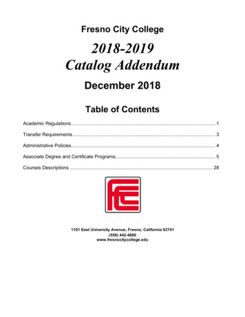
Hensen, J.L.M. & Clarke, J.A. (2000).Integrated simulation for HVAC performance prediction: state-of-the art illustration.Proceedings of the International ASHRAE/CIBSE Conference Dublin 2000 "20 20 Vision”. Atlanta: American Society ofHeating, Refrigerating, and Air-Conditioning Engineers, Chartered Institute of Building Services Engineers.Integrated Simulation for HVAC Performance Prediction: State-of-the-art IllustrationJ L M Hensen1 and J A Clarke 2 ,1Technische Universiteit Eindhoven and 2 University of StrathclydeSummaryThis paper aims to outline the current state-of-the-art in integrated buildingsimulation for performance prediction of heating, ventilating and air-conditioning(HVAC) systems. The ESP-r system is used as an example where integratedsimulation is a core philosophy behind the development. The current state andfuture developments are illustrated with case studies. It is argued that for buildingsimulation to penetrate the profession in the near future, there is a need forappropriate training and professional technology transfer initiatives.BackgroundOn average we spend around 90% of our whole life inside buildings. Energy consumption in buildingsaccounts typically for over 30 -40% of the national total annual energy consumption. HVAC systems aremajor energy users in buildings. When considering the costs of a new building, some 30% up to 50% isrelated to HVAC systems in case of commercial buildings, and 5% up to 10% in case of domesticbuildings. Hence, both with respect to environmental impact and economics, the ability to make sensibleand well based decisions regarding the choice and design of HVAC systems is of the utmost importance.Figure 1. The building as an integration of energy systemsTo provide substantial improvements in energy consumption and comfort levels, there is a need to treatbuildings, with their individual subsystems, as complete optimised entities - as schematically indicated inFigure 1 - not as the sum of a number of separately designed and separately optimised components.
Building simulation is ideal for this because it is not restricted to the building structure itself but includesthe indoor environment, while simultaneously taking into account the outdoor environment, mechanical,electrical or structural systems, and traditional and renewable energy supply systems. Building simulationcan be used to characterise and assess proposed new equipment and system integration ideas, and to aid inthe identification of such ideas. Simulation can thus be used for building analysis and design in order toachieve a good indoor environment in a sustainable manner, and in that sense to care for people now andin the future.Although a number of sophisticated computer programs have been developed in recent years these aretypically used by researchers, engineers concerned with very large building projects and for codecompliance (usually translated to simpler computer or worksheet form). It is paradoxical that althougharchitectural practices for larger firms have moved to computer design programs for the physical elementsof buildings and building systems (piping, ductwork, etc.) there has been little effort by the designcommunity to learn and apply energy analysis as a standard part of the design process. This is generallyleft to “specialists” at HVAC consulting firms after the building has been defined.Since there are real opportunities to affect the building energy use through tradeoffs in building siting,orientation, spatial definition and envelope configuration, waiting until these have been completed, andperhaps even the HVAC and other systems are defined, can result in missed opportunities for energysavings.Although most practitioners will be aware of the emerging building simulation technologies, few as yetare able to claim expertise in its application. This situation is poised to change with the advent of: performance based standards; societies dedicated to the effective deployment of simulation - such as IBPSA 1 ; appropriate training and continuing education; and the growth in small-to-medium sized practices offering simulation-based services.One thing is clear: as the technology becomes more widely applied, the demands on simulation programswill grow. While this is welcome, in that demand fuels development, it is also problematic because theunderlying issues are highly complex. Although contemporary programs are able to deliver an impressivearray of performance assessments, there are many barriers to their routine application in practice. Fourmain issues, which must be addressed, are: Firstly, since all design assumptions are subject to uncertainty, programs must be able to operateon the basis of uncertainty bands applied (automatically) to their input and output data. Such a1IBPSA: International Building Performance Simulation Association - http://www.ibpsa.org
facility is currently under development for ESP-r (16) so that performance risk may be assessedon the basis of prediction ranges resulting from uncertainty considerations applied to the input(design) parameters. Secondly, validation and calibration testing procedures must be agreed and routinely applied asthe modelling systems evolve in response to user requirements. Thirdly, program interoperability must be enabled so those design support environments evolvein response to inter-disciplinary design needs. This was the goal of the EC's COMBINE project(4) in which a prototype Intelligent, Integrated Building Design System was developed (8). Finally, a means is required to place program development on a task-sharing basis in order toensure the integrity and extensibility of future systems. This was the objective of the EPSRCfunded Energy Kernel System (7), which sought to eliminate the inefficient theoretical andsoftware de-coupling of current programs.In terms of the building life cycle, currently modelling and simulation is mainly restricted to the detaileddesign phase. However there is a definite need for use of modelling and simulation both in earlier andlater stages. Practitioners need early stage, strategic design tools. Modelling and simulation should beincorporated. Modelling and simulation can also play important roles in commissioning, auditing, controland maintenance of building systems.HVAC system modelling and simulation approachesTraditionally energy simulation in the building context focused primarily on the building side of theoverall problem domain. We now see that modelling of HVAC systems and associated (air) flowphenomena in the context of building design and building performance evaluation, is gaining more andmore interest in both the building and environmental engineering communities.In comparison to those for building side issues, the range of modelling and simulation approaches forHVAC and other environmental control systems is much greater. When allowing very coarse distinctions,one could categorise simulation systems and models as: steady-state or dynamic, general or domainspecific, stand-alone or integrated, open or closed, conceptual or explicit, process based or componentbased, sequential or simultaneous, input/output oriented or based on conservation representations, etc.In terms of steady-state versus dynamic, the current consensus amongst the modelling community stillseems to be that dynamic system operation can be approximated by series of quasi steady-state operatingconditions, provided that the time-step of the simulation is large compared to the dynamic response time
of the HVAC equipment. Obviously this is not the case in dynamic control system simulations in whichcalculations need to be performed almost on a second-by-second time scale.In terms of general versus specific, there exist several non-domain specific simulation systems that arequite popular in other engineering areas (e.g. TUTSIM). However they are not often used for buildingenergy simulation. Evidence hereof consists of the proceedings of past conferences on System Simulationin Buildings (held at the University of Liege in 1982, 1986, 1990, 1994 and 1998) or the proceedings ofpast IBPSA conferences (Vancouver 1989, Nice 1991, Adelaide 1993, Madison 1995, Prague 1997 andKyoto 1999).In case of block diagram programs the main reason for this is that, unless the building and plant is verystrongly simplified, the number of blocks' will be very large resulting in excessive CPU usage, andadministration problems (spaghetti structure). Other important reasons are: non-availability of typicalbuilding energy boundary condition generators' (for instance for processing weather data, predictinginsolation and shading, etc); non-availability of typical building energy result analyzers' (for instance forassessing comfort, converting energy to fuel, etc); users have to take care of numerical modelling issuessuch as time and space discretisation (accuracy and stability) and avoidance of algebraic loops'(solvability); users first have to learn the syntactical and semantical properties of the program.Open versus closed (meaning extensions can only be achieved via editing and re-compiling existing code)is an important issue in terms of flexibility. However, since most current building energy modellingsystems are effectively closed - and due to space constraints - this issue is also not considered here.Another way of discriminating between various approaches to building systems modelling and simulationis by considering the level of abstraction - ranging from purely conceptual to fully explicit - in terms ofuser specification and/or mathematical/ numerical representation as summarised in Table 1. (For moreelaborate descriptions of levels of abstraction, including example applications for each level, see (15).ABCDTable 1 HVAC system modelling abstraction levelsleveltypeRoom processes only; ideal plantCONCEPTUALSystem wise in terms of real systems (VAV, WCH, etc.)Component wise in terms of duct, fan, pump, pipe, etc.Subcomponent level in terms of energy balance, flowbalance, power balance, etc. VEXPLICITAt LEVEL A, specification and representation of plant systems is purely conceptual in that only the roomprocesses are considered. This means that a user may specify whether heat supply or removal iscompletely from the air (representing air heating or cooling), from within a construction (representing forinstance floor heating or a cooled ceiling), or a mix of convection and radiation (in case of for example
radiators or convectors). Disadvantages of this approach are that only the room processes are considered.All other processes in the plant (generation, distribution, and control) are assumed to be ideal.Subsequently this approach only result in gross' energy requirements and will not be able to predict fuelconsumption or energy required for distribution of working fluids. The main advantages of this approachare versatility and flexibility, and a user needs only to know about the room side processes. ESP-r is oneof the many simulation systems able to operate on this level.At LEVEL B, the specification by the user is in terms of (real) systems like variable -air-volume, variabletemperature constant volume, constant-volume zone re-heat system, four pipe fan coil, residential wetcentral heating, etc. Behind the scenes the mathematical and numerical representation is often acombination of Level A and Level C approaches. The main disadvantage of this approach is therestriction imposed on the user due to the limited number of systems that are usually on offer. The mainadvantage of this approach is the relative ease of problem definition for the user. Examples of simulationsystems operating on this level are DOE-2 and BLAST.2At LEVEL C both the specific ation by the user and the internal representation is in terms of individualplant components like fan, duct, heating coil, boiler, pump, pipe, etc., which are connected to formcomplete systems. Two main approaches can be distinguished in terms individual component models:input-output based (each separate part of the system (building zone, single component, sub-system etc.) isrepresented by an equivalent input-output relationship), and conservation equation based (each plant partis described by time-averaged discretised heat and mass conservation statements which are combined toform the plant system matrix, and which are solved simultaneously for each simulation time step).Advantages of the input-output method are: a mixture of modelling methods (analytical, numerical,internal look-up table, etc.) may be used for the different configuration components thus enablingpiecemeal component model development from simple to more complex descriptions; and because of thehighly modular structure it is relatively easy to add or change certain component models.Most contemporary system simulation environments use this input-output based modelling technique, and- nowadays - many of these incorporate numerical facilities enabling a simultaneous solution. A wellknown examples is TRNSYS.The main advantage of the conservation equation method is its implicit simultaneous solution method.The main disadvantage is that it does not allow a mixture of modelling methods. Examples ofconservation equation based systems are HVACSIM and ESP-r.2Instead of full citations, a table is attached which indicates the author organizations of the non-commercial software mentionedin this paper.
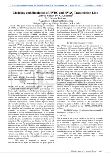
In the case of LEVEL D the specification by the user is in terms of individual components linked to formcomplete systems as in the case of Level C. However, at this level the internal representation is furtherdivided in for instance energy balance concepts, flow balance concepts, power balance concepts, etc.Each balance is then solved simultaneously for the whole system. This problem partitioning technique hasseveral advantages. The first advantage is the marked reduction in overall matrix dimensions and degreeof sparsity. A second advantage is that it is possible to easily remove partitions as a function of theproblem in hand; for example when the problem incorporates energy balance only considerations, flowbalance only considerations, energy flow, flow power, and so on. But the most important advantage isthat different partition solvers can be used which are well adapted for the equation types in question highly non-linear, differential and so on, thus enabling solution of "integral system" problems whichcannot be handled at level C. ESP-r, for example, allows simulations on this Level D.It will be obvious that there is no single best level'. As illustrated below, the optimum level depends onthe application problem at hand.ESP-r - an example of state-of-the-art in integrated simulationThe ESP-r system (6) has been the subject of sustained developments since 1974. The aim, now asalways, has been to permit an emulation of building performance in a manner that a) corresponds to thereality, b) supports early-through-detailed design stage application and c) enables integrated performanceassessments in which no single issue is unduly prominent. ESP-r is available under research (cost-free)and commercial (low cost) license from the University of Strathclyde. In both cases source code is madeavailable.ESP-r comprises a central Project Manager (PM) around which is arranged support databases, a simulator,performance assessment tools and a variety of third party applications for CAD, visualisation, reportgeneration, etc. (Figure 2). The PM's function is to co-ordinate problem definition and give/receive thedata model to/from the support applications. Most importantly, the PM supports an incremental evolutionof designs as required by the nature of the design process.The typical starting point for a new project is to scrutinise and make ready the support databases. Theseinclude hygro-thermal and optical properties for construction elements and composites, typical occupancyprofiles, pressure coefficient sets for use in problems involving air flow modelling, plant components foruse in HVAC systems modelling, mould species data for use with predicted local surface conditions toassess the risk of mould growth, and climate collections representing different locations and severity.ESP-r offers database management for use in cases where new product information is to be appended.
Figure 2. Architecture of ESP-r showing the central Project Manager and its support toolsAlthough the procedure for problem definition is largely a matter of personal preference, it is notuncommon to commence the process with the specification of a building's geometry using a CAD tool.ESP-r is compatible with two commercial CAD systems, either of which can be used to create a buildingrepresentation of arbitrary complexity (Figure 3 - left).Figure 3. Defining problem geometry using AutoCad (left) and using RADIANCE to quantifyluminance for a visual comfort/impact assessment or illuminance as input to a lighting controller(right)After importing this building geometry to the PM, constructional and operational attribution is achievedby selecting products (e.g. wall constructions) and entities (e.g. occupancy profiles) from the support
databases and associating these with the surfaces and spaces comprising the problem. It is at this stagethat the simulation novice will appreciate the importance of a well-conceived proble m abstraction, whichachieves an adequate resolution while minimising the number of entities requiring attribution.The PM provides coloured, textured physically correct images via the RADIANCE system (22) and wireframe photomontages via the VIEWER system (20), automatically generating the required input modelsand driving these two applications (Figure 3 - right).As required, component networks are now defined representing HVAC systems (1, 5, 13), distributedfluid flow (for the building-side air or plant-side working fluids) (13, 14) and electrical power circuits(19). These networks are then associated with the building model so that the essential dynamicinteractions are preserved.Control system definitions can now proceed depending on the appraisal objectives. Within ESP-r thisinvolves the establishment of several closed or open loops, each one comprising a sensor (to measuresome simulation parameter at each time-step), an actuator (to deliver the control signal) and a regulationlaw (to relate the sensed condition to the actuated state). Typically, these loops are used to regulate plantcomponents, to associate these components with building zones, to manage building-side componentssuch as blinds, and to co-ordinate flow components (e.g. window opening) in response to environmentalconditions. Control loops can also be used to change portions of a problem with time (e.g. substitutealternative constructions) or impose replacement parameters (e.g. heat transfer coefficients).For specialist applications, the resolution of parts of the problem can be selectively increased, forexample: ESP-r's default one-dimensional gridding scheme representing wall conduction can be enhancedto a two- or three-dimensional scheme to better represent a complex geometrical feature orthermal bridge (17). A one-, two- or three-dimensional grid can be imposed on a selected space to enable a thermallycoupled computational fluid dynamics (CFD) simulation (9, 18). Special behaviour can be associated with a material, e.g. electrical power production viacrystalline or amorphous silicon photovoltaic cells (11). Models can be associated with material hygro-thermal properties to define their moisture and/ ortemperature dependence in support of explicit moisture flow simulation and mould growthstudies(3).The PM requires that a record be kept of the problem composition and to this end is able to store andmanipulate text and images which document the problem and any special technical features. It is also
possible to associate an integrated performance summary with this record (Figure 4) so that the designand its performance can be assessed without having to commission further simulations.The problem - from a single space with simple control and prescribed ventilation, to an entire buildingwith systems, distributed control and enhanced resolutions - can be passed to the ESP-r simulator where,in discretised form, the underlying conservation equations are numerically integrated at successive timeintervals over some period of time. Simulations, after some minutes or hours, result in time-series of"state information" (temperature, pressure, etc.) for each discrete region.ESP-r's results analysis modules are used to view the simulation results and undertake a variety ofperformance appraisals: changes to the model parameters can then follow depending on these appraisals.While the range of analyses are essentially unrestricted, interrelating the different performance indicators(Figure 4), and translating these indicators to design changes, is problematic because of the lack ofperformance standards and the rudimentary level of simulation scholarship and training.Example applicationsThere are a whole range of issues in HVAC design and performance prediction that would/could benefitfrom an integrated approach using modelling and simulation as opposed to the currently used moretraditional engineering techniques. Examples are: critical sizing, integrated energy performanceevaluation, operation optimisation, real time pricing operation, predictive control, mixed mode systems,structure supported systems, new developments, etc. The best way to illustrate both several applicationareas and previously discussed modelling approaches, is by presenting case studies. Due to spaceconstraints, this needs to be limited to two very brief descriptions. (Other and more elaborate, case studiesmay be found in, for example, (2 and 10).). Although the following examples could easily have beenmodelled using other building energy simulation environments, they are all based on ESP-r for obviousreasons.Critical sizing using conceptual modellingConsider the building as indicated in Figure 4, which consists of 3 zones: demo/sales area, office, andattic. The building - located in the Greater London area - is used for demonstration and sales purposes.Both in view of the products being marketed and the customers/personnel involved the air temperature inthe demo/sales area should be kept within certain limits. For summer conditions, the initial suggestion isto keep the indoor air temperature below 26o C continuously.
Figure 4 Graphical feedback of building modelIn the traditional approach, manual calculations would be performed to calculate the necessary size of thecooling equipment and the rest of the HVAC system. This would typically be based on extreme weatherconditions, and in one way or another (usually quite simplified) the dynamic characteristics of thebuilding would be taken into account.Table 2 Frequency distribution of cooling loads for demo/sales 22535000110447100Using dynamic building energy simulation, on the other hand, it is relatively easy to generate superiorinformation in terms of cooling equipment sizing, even when using a conceptual approach to modellingthe system. This conceptual approach makes use of the fact that the energy balance of the buildingeffectively comprises two unknowns: indoor air temperature and cooling/heating load. If one of the two is fixed' all other temperatures and energy fluxes can be calculated.The above was done for all hours of the July - September period of some climatic reference yearapplicable to the London area. From this it was found that the maximum (dynamic) cooling load for thedemo/sales area would be 2910 W, with a frequency distribution of loads as indicated in Table 2.
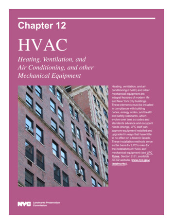
From Table 2 it is obvious that the cooling plant would operate at very low loading levels during most ofthe time. The next question is what are the consequences of installing a lesser capacity cooling system.For this, a sequence of simulations was carried out in which the plant cooling capacity was step-wisedecreased. The results, in terms of air temperature occurrences and cooling plant energy consumption aresummarised in Table 3.Table 3 Demo/sales area air temperature occurrences and cooling energy demands in case ofreduced cooling capacityCoolingCapacityW291025002000150010005000 26h220821792071195017481409869Air temperature demo/sales 5191837670502781459265267275208150 16520Although this case study represents a -perhaps - simplistic approach to system simulation (for whichalmost no parameters were needed to describe the system), some valuable design conclusions can still bedrawn. It is only with results such as in Table 2 and Table 3 (which can only be generated using dynamicsimulation), that the designer, in consultation with the client, will be able to critically size the system.Control performance evaluation using explicit modellingThis second case study concerns a historical building in Edinburgh, Scotland, which is being convertedinto a museum and art storage. In view of the artefacts being displayed and stored in the museum, somespaces need strict temperature and humidity control. A study (12) was carried out in order to predict theperformance of a HVAC system as suggested by the client (see Figure 5).Some results in terms of relative humidity control are shown in Figure 6. From the simulation results itwas evident that for low latent load levels, the HVAC system as originally proposed would be capable ofmaintaining the desired temperature and relative humidity levels across a range of typical and designweather conditions. However, should these latent loads increase then an alternative HVAC systemoffering closer control on humidity would be required. Figure 6 compares relative humidity controlpossible with two HVAC system arrangements: the originally proposed system, and a modified system(bottom Figure 5) in which each storage space is independently serviced.
Figure 5. HVAC system / control as originally suggested (top), and an alternative arrangement (bottom)Figure 6. Relative humidity control performance predictions for both HVAC configurationsAs implied by Figure 5, this case represents an explicit HVAC modelling approach. Relative to the firstcase, the number of parameters, which are needed to describe the actual system components and theircontrol, is very high. However the information to be gained from the simulations is also much richer. Incontrast to the conceptual level where simulations are based on some presumed indoor temperature profile
(or maximum available capacity), at this level of abstraction it is actually possible to predict airtemperature, relative humidity and fuel consumption given a building, plant, and control configuration.Conclusions and future workIt may be concluded that - except for highest level conceptual modelling - HVAC modelling andsimulation is rather complicated from a user point of view. Not surprisingly the complications grow withthe level of explicitness. This is because at the same time, the required/ assumed user knowledge ofHVAC systems increases, the sheer number of plant definition parameters grows, the availability of datafor those parameters decreases (manufacturers often do not have the data available which is needed forthe models), and analysing the (increasing amount of) results becomes more complicated.Also from a developer point of view the complications (and challenges!) increase with the level ofexplicitness and detail. This is due to the physics underlying say a component, but more often it is due tothe interactions with other parts of the HVAC system or with
HVAC system modelling and simulation approaches . Traditionally energy simulation in the building context focused primarily on the building side of the overall problem domain. We now see that modelling of HVAC systems and associated (air) flow phenomena in the context of building design and building performance evaluation, is gaining more and