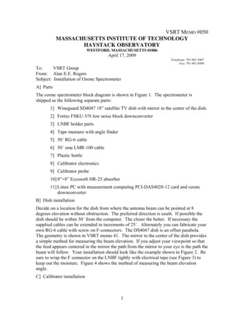
Transcription
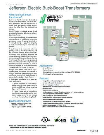
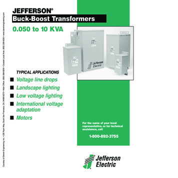
Courtesy of Steven Engineering, Inc. Ÿ 230 Ryan Way, South San Francisco, CA, 94080-6370 Ÿ Main Office: (650) 588-9200 Ÿ Outside Local Area: (800) 258-9200 Ÿ www.stevenengineering.com JEFFERSONBuck-Boost Transformers0.050 to 10 KVATYPICAL APPLICATIONS Voltage line dropsLandscape lightingLow voltage lightingInternational voltageadaptation MotorsFor the name of your localrepresentative, or for technicalassistance, call1-800-892-3755 JeffersonElectric
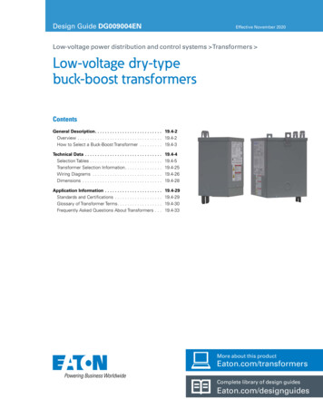
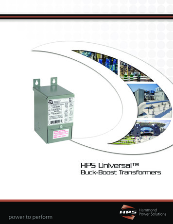
Courtesy of Steven Engineering, Inc. Ÿ 230 Ryan Way, South San Francisco, CA, 94080-6370 Ÿ Main Office: (650) 588-9200 Ÿ Outside Local Area: (800) 258-9200 Ÿ www.stevenengineering.comBuck-Boost Transformersfeatures & benefits Copper leadwire termination used for the primary, secondary and groundfor easy, flexible connections. Heavy sheet metal enclosures for better durabilityin severe industrial applications. Large connection compartment with knockouts for ease ofwiring and installation. Encapsulated with electrical grade epoxy and silica sand to completelyseal the core and coils from moisture and contaminants. Heat applied ASA-61 Gray Powder Coat Finish to resist corrosion inindustrial environments. Quiet operation for more flexibility in choice of mounting locations. Convenient lifting hooks on all units above 3 KVA to make installation easier. Type NEMA 3R enclosures for outdoor use to protect against rain, sleet or ice. Cores made from high quality electrical steel for increased efficiency andlower operating costs. Built in accordance with ANSI C57.12. Convenient wall mount design. UL Listed and CSA Approved. 50/60 Hz. operation on transformers 2 KVA and smaller for more versatility. Slotted mounting holes for quick and easy mounting. 180 C insulation system standard with 115 C temperature rise for longer,more reliable life. Wiring diagram permanently affixed to wiring compartment cover toavoid loss. Meets or exceeds all applicable NEMA, ANSI, OSHA, UL and CSA requirements. Made in U.S.A.54 JeffersonElectric1-800-892-3755
Courtesy of Steven Engineering, Inc. Ÿ 230 Ryan Way, South San Francisco, CA, 94080-6370 Ÿ Main Office: (650) 588-9200 Ÿ Outside Local Area: (800) 258-9200 Ÿ www.stevenengineering.comBUCK-BOOSTJefferson Electric single-phase Buck-Boost transformers are the most economical meansavailable for stepping voltages up or down in many common applications. They can be used asisolating (or insulating) transformers for transforming standard line voltages to low secondaryvoltages. Also to buck or boost off-standard line voltages to satisfy standard load voltagerequirements when hooked in Auto Configuration.These transformers are designed for use on single- or three-phase circuits to supply 12/24 or 16/32volt secondaries with 120/240 volt primary, and 24/48 volt secondaries with 240/480 volt primary.When used in Auto Configuration, these small, compact and lightweight units will handle alarge KVA load in comparison to their physical size and relative cost. When usedas isolation transformers, they have innumerable low voltage applications.The difference between anautotransformer and anisolation transformer.In an autotransformer, the input (or primary)and the output (or secondary) areelectrically connected, while in an isolationtransformer they are completely separated,as shown at right.Only a portion of the electrical energy ischanged in an autotransformer, theremainder flowing directly between theprimary and secondary. In an isolationtransformer, all the energy is transformed. Forthese reasons, an autotransformer is smaller,lighter and less costly than a comparableisolation transformer.AutotransformerIsolation (or Insulating)TransformerSolve over/under line voltage problemsefficiently and economically.Electrical equipment is manufactured to operate mostefficiently when the line voltage is equal to or nearlyequal to the nameplate rating of the equipment. A motoroperated at a voltage substantially under its nameplaterating may run constantly on the starting windings,resulting in overheating and possible burn-out. The samemotor operated at a voltage substantially over itsnameplate rating is subject to excessive heat rise,often extending beyond the insulation temperature limits,which may eventually cause the motor to burn out.1-800-892-3755CAUTION: Buck-Boost transformers willnot compensate for fluctuating linevoltages. They should only be usedwhen line voltage is relatively constant. JeffersonElectric55
Courtesy of Steven Engineering, Inc. Ÿ 230 Ryan Way, South San Francisco, CA, 94080-6370 Ÿ Main Office: (650) 588-9200 Ÿ Outside Local Area: (800) 258-9200 Ÿ www.stevenengineering.comBuck-Boost TransformersHow to Use the Buck-Boost Rapid Selector Charts:You will need the following information:Line voltage:This can be determined by measuring the supply line voltage with a voltmeter.Load voltage:The voltage at which your equipment was designed to operate. Usually listed on the equipment nameplate.Load KVA or load amps:One of these will usually be listed on the nameplate. You do not need both.Supply line and equipment frequencies:This will be either 50 or 60 cycles. The supply line frequency must be the same as the frequency of theequipment to be operated.Supply line and equipment phase:Either single-phase or three-phase. The line phase must be the same as the equipment.The type of electrical configuration:Delta or Wye.Follow These Five Easy Steps:1.Find the appropriate single-phase, three-phase deltaor three-phase wye table.2.Read down the voltage column and find the nearestratio of required load voltage to line voltage for theapplication desired. (High and low voltage may beeither input or output voltage depending on thecircumstances.)3.Reading horizontally across the line beginning withyour application voltage ratio, locate in one of theKVA columns a KVA capacity equal to or larger thanyour load requirement.4.Note the two digit number at the top of the KVAcolumn listing the KVA capacity you require.5.In the catalog number column, add these two digitsto the catalog number next to the voltage ratio youfound in step one.56 JeffersonElectricEXAMPLE: (Assume the following information)1. A reasonably constant line voltage of 440 volts.2. A required equipment voltage of 480 volts.3. 26.0 KVA load capacity needed.4. Single-phase line and equipment.In the voltage column, 437 is closest to our line voltageof 440. The 480 high voltage meets our requirementsexactly.Reading horizontally across this line, find 30.0 KVA, theclosest larger KVA to our required 26.0.Going to the very top of this column, take the two digitnumber, 81, and add it on the end of the catalog number onthe same line as our high/low voltage. The catalog number216-14, with 81 added on the end, is 216-1481.The listings here do not cover all the possibleapplications of these versatile transformers.Please call for advice or a quotation onspecial applications.1-800-892-3755
Courtesy of Steven Engineering, Inc. Ÿ 230 Ryan Way, South San Francisco, CA, 94080-6370 Ÿ Main Office: (650) 588-9200 Ÿ Outside Local Area: (800) 258-9200 Ÿ www.stevenengineering.comBUCK-BOOSTSingle-Phase KVAKVACapacityCapacity ofof EncapsulatedEncapsulated PowerformersPowerformers Single-PhaseMAXIMUM LOAD CAPABILITIESMAXIMUM LOAD 810521855.0114Wiring Diagram 56AWiring Diagram 56BWiring Diagram 56CWiring Diagram 56D1-800-892-3755 7
Courtesy of Steven Engineering, Inc. Ÿ 230 Ryan Way, South San Francisco, CA, 94080-6370 Ÿ Main Office: (650) 588-9200 Ÿ Outside Local Area: (800) 258-9200 Ÿ www.stevenengineering.comBUCK-BOOSTThree-Phase KVA Capacity of Encapsulated Powerformers Connected in Open-DeltaMAXIMUM LOAD CAPABILITIES REQUIRING TWO 8321895.0114Wiring Diagram 57AWiring Diagram 57BWiring Diagram 57CWiring Diagram 57D58 57D57D57D57C57C57A57B57C57D57D57B57D57C57C57D
Courtesy of Steven Engineering, Inc. Ÿ 230 Ryan Way, South San Francisco, CA, 94080-6370 Ÿ Main Office: (650) 588-9200 Ÿ Outside Local Area: (800) 258-9200 Ÿ www.stevenengineering.comBUCK-BOOSTThree-Phase KVA Capacity of Encapsulated Powerformers Connected in WyeMAXIMUM LOAD CAPABILITIES REQUIRING THREE .845
amps 3.95 5.93 9.89 19.7 29.6 39.5 59.3 79.1 118 197 . 218/240 216-11 load kva 1.00 1.5 2.5 5.0 7.5 10.0 15.0 20.0 30.0 50.0 56d amps 4.58 6.88 11.4 22.9 34.4 45.8 68.8 91.7 137 229 225/240 216-12 load kva 1.5 2.25 3.75 7.5 11.2 15.0 22.5 30.0 45.0 75.0 56c amps 6.66 10.0 16.6 33.3 49.7 66.6 100 133 200 333 230/276 216-14 load kva .57 .86 1.43 2.8 4.3 5.7 8.6 11.5 17.2 28.7 56b amps 2.50 3 .
