Transcription
Introduction to Electrical PowerRequirements for BuildingsCourse No: E02-006Credit: 2 PDHJ. Paul Guyer, P.E., R.A., Fellow ASCE, Fellow AEIContinuing Education and Development, Inc.9 Greyridge Farm CourtStony Point, NY 10980P: (877) 322-5800F: (877) 322-4774info@cedengineering.com
An Introductionto ElectricPowerRequirementsGuyer Partners44240 Clubhouse DriveEl Macero, CA 95618(530)7758-6637jpguyer@pacbell.net J. Paul Guyer 2010J. Paul Guyer, P.E., R.A.Paul Guyer is a registered civil engineer,mechanical engineer, fire protection engineer,and architect with over 35 years experience inthe design of buildings and relatedinfrastructure. For an additional 9 years hewas a senior advisor to the CaliforniaLegislature on infrastructure and capital outlayissues. He is a graduate of Stanford Universityand has held numerous national, state andlocal positions with the American Society ofCivil Engineers and National Society ofProfessional Engineers.1
This course is adapted from the Unified Facilities Criteria of the United States government,which is in the public domain, has unlimited distribution and is not copyrighted. J. Paul Guyer 20102
CONTENTS1. PRELIMINARY DATA1.1 SCOPE1.2 LOAD DATA1.3 LOAD ANALYSIS1.4 TERMINOLOGY2. ESTIMATION OF LOADS2.1 PREPARATION OF LOAD DATA2.2 INDIVIDUAL LOADS2.3 EMERGENCY LOADS2.4 AREA LOADS2.5 ACTIVITY LOADS3. SELECTION OF ELECTRIC POWER SOURCE3.1 ELECTRIC POWER SOURCES3.2 ACCEPTABLE ELECTRIC POWER SOURCES3.3 PURCHASED ELECTRIC POWER REQUIREMENTS J. Paul Guyer 20103
1. PRELIMINARY DATA1.1 SCOPE. This discussion provides an introduction to the criteria necessary for theproper selection of electric power sources and distribution systems. It covers preliminaryload estimating factors and electrical power sources.1.2 LOAD DATA. Before specific electric power sources and distribution systems canbe considered, realistic preliminary load data must be compiled. The expected electricpower demand on intermediate substations, and on the main electric power supply,shall be calculated from the connected load layout by applying appropriate factors.Determine these factors by load analysis and by combining loads progressively. Tocombine the loads, start at the ends of the smallest feeders and work back to theelectric power source. Because all loads must be on a common kilowatt (kW) or kilovoltampere (kVA) basis, it is necessary to convert motor horsepower ratings to inputkilowatts or kilovolt-amperes before combining them with other loads already expressedin those terms. Preliminary electric power load estimates can be made by using theapproximate value of one kilovolt-ampere of input per horsepower (hp) at full load.Preliminary estimates of lighting loads may be made by assuming watts per ft2 ofbuilding area.1.3 LOAD ANALYSIS. To determine appropriate load estimating factors, using thetables and factors in this manual as guides to analyze the characteristics of each load.Consider items such as environmental conditions of weather, geographical location, andworking hours, as the situation dictates. Notice that when the load densities in w/ft2 areused only in preliminary estimates, the demand and load factors will be used in the finaldesigns.1.4 TERMINOLOGY. Five terms are essential to the analysis of load characteristics:demand factor, coincidence factor, diversity factor, and maximum demand. These termsare defined below. J. Paul Guyer 20104
1.4.1 DEMAND FACTOR. The demand factor is the ratio of the maximumdemand on a system to the total connected load of the system orEQUATION: Demand factor Maximum demand loadTotal load connected1.4.2 COINCIDENCE FACTOR. The coincidence factor is the ratio of the maximumdemand of a system, or part under consideration, to the sum of theindividual maximum demands of the subdivisions orEQUATION: Coincidence factor Maximum system demandSum of individual maximum demands1.4.3 DIVERSITY FACTOR. The diversity factor is the reciprocal of the coincidencefactor orEQUATION: Diversity factor Sum of individual maximum demandsMaximum system demand1.4.4 LOAD FACTOR. The load factor is the ratio of the average load overa designated period of time, usually 1 year, to the maximum load occurring inthat period orEQUATION: Load factor Average loadMaximum load1.4.5 MAXIMUM DEMAND. The maximum demand is the integrated demand for aspecified time interval, i.e., 5 minutes, 15 minutes, 30 minutes, or other appropriate timeintervals, rather than the instantaneous or peak demand. J. Paul Guyer 20105
2. ESTIMATION OF LOADS2.1 PREPARATION OF LOAD DATA. Load data are generally computed in steps suchas:a) individual loads,b) area loads, andc) activity loads.A particular design problem may be limited to step a), to steps a) and b), or mayencompass steps a), b), and c). This section outlines each step as a separate entity,dependent only on previous steps for data.2.2 INDIVIDUAL LOADS. Individual loads are those with one incoming servicesupplying utilization voltage to the premises. In general, these loads would comprisesingle structures. Large structures could contain more than one function. Under thiscondition, factors that have been developed and (refer to Table 2.1) would be used.2.2.1 LIGHTING. To eliminate lighting loads, divide a facility area into its significantcomponents by function (for example, office, storage, mechanical, and corridor).Determine the average lighting level and type of light source for each area. Considerrequirements for supplementary lighting (for example, floodlighting, security lighting, andspecial task lighting). Preliminary load estimates may be made based on the followingload allowances:a) 1 W/sf for each 6 to 8 fc of incandescent illumination.b) 1 W/sf for each 15 to 20 fc of fluorescent illumination.c) 1 W/sf for each 12 to l8 fc of mercury vapor illumination.d) 1 W/sf for each 26 to 36 fc of metal halide illumination.e) 1 W/sf for each 33 to 54 fc of high pressure sodium illumination. J. Paul Guyer 20106
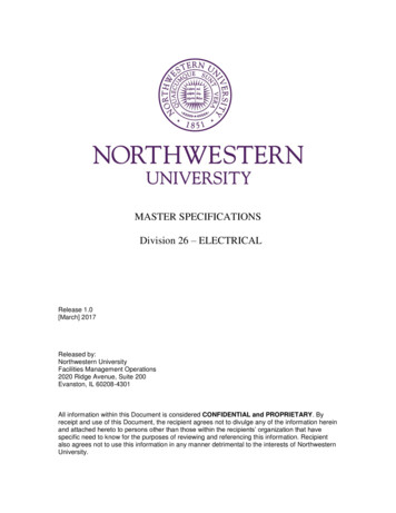
2.2.2 SMALL APPLIANCE LOADS. Small appliance loads shall include those servedby general purpose receptacles. In general, the dividing of areas by function forestimating lighting loads will serve for estimating small appliance loads. Thedetermination of loads requires not only knowledge of the function of an area, but towhat extent its occupants use small appliances. For example, an office area demandmay average about 1 W/sf but could vary from a low of 0.5 W/sf to a high of 1.5 W/sfdepending on the specific tasks to be performed. A minimum of 0.1 W/sf for auditoriumsto a maximum of 2.5 W/sf for machine shops is possible, although the upper limit wouldoccur very rarely. Mechanical spaces in building storage areas and similar spaces inwhich outlets are provided but infrequently used are usually neglected in computingloads, except for special cases.2.2.3 ELECTRIC POWER LOADS. Electric power loads shall include all loads otherthan lighting loads and those served by general purpose receptacles and comprise theenvironmental system electric power requirements and the facility occupancy equipmentelectric power requirements.2.2.4 SYSTEM LOSS. A system loss of approximately 6 percent, based on calculatedmaximum demand, should be added to the building load.2.2.5 DEMAND AND LOAD FACTORS. The demand and load factors for a specificfacility will vary with the division of load and hours of usage. Refer to Tables 2.2 and 2.3for values that can be applied to determine demand and load factors. Table 2.4 isincluded as a guide and an aid in illustrating the method of determining loads, which arecalculated for a particular type of building. The values given are empirical and will varyfrom activity to activity, and may vary from one facility to another within an activity.Annual hours use of demand must be determined for each case in accordance withmethods of operation and characteristics of the installation. Such factors should beused for quick estimating purposes and as a check when a more precise calculation isundertaken (refer to Table 2.4). J. Paul Guyer 20107
2.2.5.1 Guides for Demand Factors. For guides on the selection of demand factors,refer to Table 2.5.2.2.5.2 Guides for Load Factors. Guides for the selection of load factors indicate theneed for special considerations (refer to Table 2.6).2.2.6 LOAD GROWTH. Determine the requirements for load growth for anticipatedusage and life expectancy with particular attention to the possibility of adding heavyloads in the form of air conditioning, electric heating, electric data processing, andelectronic communication equipment. Before determining the size of service andmethod of distribution to a facility, an economic analysis shall be made to determine themost feasible way of serving this future load. This analysis shall include the effect on theexisting installation if future loads require reinforcing or rehabilitation of the servicesystem. J. Paul Guyer 20108
Table 2.1Factors for Individual FacilitiesDemand FactorCommunications – buildings60-65Telephone exchange building55-70Air passenger terminal building65-80Aircraft fire and rescue station25-35Aircraft line operations building65-80Academic instruction building40-60Applied instruction building35-65Chemistry and Toxicology Laboratory70-80Materials Laboratory30-35Physics Laboratory70-80Electrical and electronics systems laboratory20-30Cold storage warehouse70-75General warehouse75-80Controlled humidity warehouse60-65Hazardous/flammable storehouse75-80Disposal, salvage, scrap building35-40Hospital38-42Laboratory32-37Dental Clinic35-40Medical Clinic45-50Administrative Office50-65Single-family residential housing60-70Detached garages40-50Apartments35-40Fire station25-35Police station48-53Bakery30-35Laundry/dry cleaning plant30-35K-6 schools75-807-12 schools65-70Churches65-70Post Office75-80Retail Auto repair shop40-60Hobby shop, art/crafts30-40Bowling alley70-75Gymnasium70-75Skating rink70-75Indoor swimming pool55-60Theater45-55Library75-80Golf clubhouse75-80Museum75-80 J. Paul Guyer 2010Load 510-1525-508-1330-3515-2030-359
Table 2.2Demand Factors for Specific LoadsTable 2.3Annual Hours of Demand Usage for Specific Loads J. Paul Guyer 201010
MOTORSGENERALMISCELLANEOUSFRACTIONALAND SMALLAPPLIANCES1.0100 kw10%LIGHTINGAIRCONDITIONINGTOTAL1. Watts/SF1.02.74.59.22. Connected load100 kw265 kw450 kw915 kw3. Specific load30%75%70%demand factor4. Maximum demand30 kw10 kw200 kw315 kw555 kwload (line 2 x line 3)5. Annual operating1200 hrs1500 hrs2200 hrs1600 hrs(1-shift) usage6. Annual usage3615440504995(megawatt hrs)(line 4x line 5)Demand factor –60%Formula (1) line4/line 2Load factor (4) line20%6/(line 4 x 8760 hrs)Note 1: Calculated for a 100,000 sf building. See tables 2.2 and 2.3 for data for lines 3 and 5respectively. Load growth is included in connected load. Maximum demand load includes allowance forsystem loss. For this illustration, the coincidence factor occurring when individual loads are added isconsidered to be 1.0 and has not been shownTable 2.4Academic Building Demand and Load Factor Calculations J. Paul Guyer 201011
Selection of factors in upper half of range forSelection of factors in lower half of range forconditions described belowconditions described belowGENERAL GUIDESFacilities in active use and approaching maximumFacilities of intermittent use or not being fullycapacityutilized.Loads predominantly lighting.Motor loads made up of a number of independentlyoperated small motors.Loads predominantly heating.Motor loads controlled automatically unless controldepends upon weather conditions.Loads dominated by one or two large motors.OPERATIONAL, EDUCATIONAL AND TRAINING FACILITIESInstruction buildings with little or no electricLarge instruction buildings with electricalequipment.demonstration and training equipmentMAINTENANCE AND PRODUCTION FACILITIESShops and facilities when engaged in massNo special guides.production of similar parts.RESEARCH, DEVELOPMENT AND TEST FACILITIESFacilities used for repetitive testing of material orNo special guides.equipment.WAREHOUSES AND SUPPLY FACILITIESRefrigerated warehouses in the South.Warehouses with many items of electric materialsDehumidified warehouses in Mississippi Valley and handling equipment, including cranes andalong seacoasts. Warehouses for active storage.elevators.HOSPITAL AND MEDICAL FACILITIESNo special guides.No special guides.OFFICES AND ADMINISTRATIVE FACILITIESLarge administrative buildings with mechanicalCasual offices, offices used infrequently, or officesventilation and air conditioning. (Group largein which there is little prolonged desk work.administrative buildings together only whenadministration is a significant part of total activityload.)RESIDENTIAL AND COMMUNITY FACILITIESApartments and similar residential complexes.Food service facilities where load is primarilycooking and bakingRestaurants, shopping center buildings, cafeteriasand other food service facilities when gas or steamis primary fuel.UTILITIES AND SITE IMPROVEMENTSCentral heating plants serving extended areas andNo special guides.buildings. Water pumping stations servingextended areas or carrying most of load of watersystems. Central station compressed air plants.Table 2.5Guides for Selection of Demand Factors J. Paul Guyer 201012
Selection of factors in upper half of range forconditions described belowSelection of factors in lower half of range forconditions described belowGENERAL GUIDESFacilities operated on two or more shiftsFacilities of intermittent use or not being fully utilized.Loads that are primarily fluorescent or high intensityInactive facilities.discharge lighting.Many small independently operated motors.Large motor loads when the load consists of relativelysmall numbers of motors.Electronic equipment continuously operated forWholesale type service facilities.immediate use.Cooling and dehumidification loads for year-roundclimate control in Southern climates.Retail-type service loads and loads that are in active use.OPERATIONAL, EDUCATIONAL AND TRAINING FACILITIESLarge permanent instruction buildings in active use.Special purpose instruction and training facilities notregularly used.MAINTENANCE AND PRODUCTION FACILITIESShops with battery charging equipment operated afterWelding loads or loads made up primarily of weldinghours.equipment.Active shops at full employment.Job-order workshops.Mass production shops.Shops with large, heavy special function machines.Large induction or dielectric heating loads.RESEARCH, DEVELOPMENT AND TEST FACILITIESNo special guides.No special guides.WAREHOUSES AND SUPPLY FACILITIESRefrigerated and dehumidified warehouses in the SouthRefrigerated warehouses in North.or humid climates.Warehouses for active storage and in continuous use.Warehouses with large materials handling equipmentloads.HOSPITAL AND MEDICAL FACILITIESMedical treatment facilities with daily operating hours and No special guides.in active use.OFFICES AND ADMINISTRATIVE FACILITIESLarge, active, well-lighted offices with ventilation and airNo special guides.conditioning equipment.RESIDENTIAL AND COMMUNITY FACILITIESSupermarkets.Restaurants and supermarkets serving only one meal aday.Gymnasiums and physical therapy facilities.Restaurants and supermarkets with gas/steam foodpreparation equipment.Housing facilities at schools and training centers.Churches used primarily one day a week.Laundries with dry cleaning plants.Supermarkets operated less than 8 hrs/day.Gatehouses operated less than 24 hrs/day.UTILITIES AND SITE IMPROVEMENTSHeating plants that supply both heating and processHeating plants in the South.steam.Water plants with little power load.Air conditioning plants for year-round control ofenvironment in South.Compressed air plants consisting of many bankedcompressors operating automatically.Table 2.6Guides for Selection of Load Factors J. Paul Guyer 201013
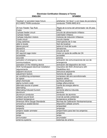
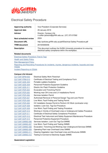
2.3 EMERGENCY LOADS. The determination of emergency electric powerrequirements is based on three types of loads:a) minimum essential load,b) emergency load for vital operations, andc) uninterruptible (no-break) load.When the three categories of emergency electric power requirements have beenascertained, determine where local emergency facilities are required, where loads maybe grouped for centralized emergency facilities, and what loads are satisfied by thereliability of the general system. Base the aforementioned determinations on safety,reliability, and economy, in that order.2.4 AREA LOADS. Area loads consist of groups of individual facility loads served by asubdivision of the electric distribution system. The term "area" applies to the next largersubdivision of an overall distribution system. Demand loads for an area must be knownfor sizing the distribution wiring and switching, and in a large installation will be requiredfor the design of substations serving the area. Table 2.7 gives an example of how thecoincident peak demand is calculated.2.4.1 GENERAL LOADS. To obtain the general load, add roadway lighting, arealighting, obstruction lighting, and other loads not included in individual facility loads.2.4.2 COINCIDENCE FACTOR. Determine the maximum expected demands, takinginto consideration whether loads within the area peak at the same or at different times.2.4.2.1 Relationships. Figure 2.1 indicates the relationship that exists between the loadfactor of individual facility loads and the coincidence of their peak demands with thepeak demand of the group. Table 2.8 is Figure 2.1 in tabular form with values shown tothe nearest whole dollar, except for low load factors. J. Paul Guyer 201014
2.4.2.2 Selection. Areas with relatively insignificant residential type loads, where theload curve indicates that most of the electric power consumed in the area is used duringthe 40 normal working hours of a week, have coincidence factors at the higher end ofthe range.2.4.2.3 Electric Power Consumption. In general, areas where large amounts ofelectric power are consumed outside the usual 40 working hours a week have acoincidence factor at the lower end of the range (examples are hospitals, areasoperated on two or more shifts, or large barracks type activities). The upper limit of therange is for a 40 hour per week operation; the lower limit is for a 60 hour per weekoperation. J. Paul Guyer 201015
DescriptionFuel oil pumphouseSub-totalFilling stationFilling stationbuildingReceiver buildingTransmitter buildingSub-totalTacan buildingRadar buildingAircraft fire andrescue stationAircraft ruction buildingSub-totalOperational trainerfacilityAircraft overhauland repair shopPaint/finishinghangarEngine preparationand storage shopEnginemaintenance shopSub-totalEngine test cellMissile equipmentmaintenance facilityAuto vehiclemaintenance facilityFire stationTotalconnectedload, kwDemandfactor, %Maximumdemand,%Loadfactor, %Coincidencefactor, %Coincidencepeak, 212.3TotalSystem loss(6%)Grand total33251943429(1) The coincidence factor has been increased to allow for low load factor and number of facilities in the area.(2) The coincidence factor has been increased because of the relative magnitude of the load.Table 2.7Method of Calculating Coincident Peak Demand J. Paul Guyer 201016
Figure 2.1Theoretical Relationship between Load Factor and Coincidence Factor J. Paul Guyer 201017
LOAD OINCIDENCE FACTOR, %Loads, 68736873697369LOAD 979899100COINCIDENCE FACTOR, %Loads, 8989999100100Table 2.8Relationship Between Load Factor and Coincidence Factor J. Paul Guyer 201018
their load factors influence the individual load coincidence factor. The coincidencefactors in Table 8 apply for groups of l00 or more individual loads. These coincidencefactors can also be used for groups of as few as 30 to 50 individual loads if their loadfactor is 0.30 or greater. For areas of fewer individual loads, the mathematicalrelationship from IEEE Technical Paper 45-116 provides a basis for estimating theconnected coincidence factor as shown by the following equation:2.4.2.4 Individual Loads. The coincidence factors in Table 8 are based on theindividual loads in a group being substantially the same size. If a single load or smallgroup of loads in an area represents a substantial percentage of overall load, thecoincidence factors as given in Table 8 will no longer apply. With an individual load,increase the coincidence factor to a value commensurate with its effect on the overallarea load. This is not in addition to, but in place of, the normal coincidence factor.Determine this value by considering intergroup coincidence factors given in paragraph2.4.2.5. For a small group, determine the coincidence peak load, and to this apply theappropriate intergroup coincidence factor to obtain the coincidence peakload for the area.2.4.2.6 Groups of Loads or Areas. Where groups of loads within an area, orareas within a facility are combined, an additional intergroup coincidencefactor will exist. For loads of a similar nature, the intergroup coincidencefactor should be in the range 0.93 to 1.00. If loads of a varying nature(evening loads and daytime loads) are combined, the intergroup coincidencefactor should be in the range of 0.70 to 1.00. The lower values will occur J. Paul Guyer 201019
when the magnitudes of the loads are nearly balanced, and the higher oneswhen the combined load is predominantly one type.2.4.3 LOAD GROWTH. In addition to planned expansion, increased application ofelectric equipment will generate an increase in load. When sizing components, such astransformers or feeders for the area system, consider possible load growth in addition tothat included in the determination of individual loads.2.4.4 SYSTEM LOSSES. Add distribution system losses to estimated area demands.For a good approximation, use 6 percent of the calculated maximum demand.2.4.5 EMERGENCY LOADS. Review the overall emergency requirements for the area,based on criteria for the facility or as furnished by the using agency, to determine thefollowing:a) The emergency loads that may be combined in groups to take advantage ofthe coincidence factor.b) The type of distribution system needed for reliability and to economicallysatisfy at least the less critical emergency load requirements.This reliability can be provided only if the source of electric power is not thedetermining factor.c) Area loads that must be added to individual emergency loads; for example,security lighting and minimum roadway lighting.2.4.6 EXPANSION. The planned development of the area, as shown on the activitygeneral development map, shall be considered for requirements of future expansion.2.5 ACTIVITY LOADS. Activity loads are loads that consist of two or more area loadsserved from a single electric power source and an integrated distribution system. J. Paul Guyer 201020
2.5.1 GENERAL LOADS. Area loads used for determining activity coincidence demandshould be the area coincident demand exclusive of allowance for load growth.2.5.2 COINCIDENCE FACTOR. Where dissimilar areas, whether residential,administrative, or industrial, are part of an activity, make a careful analysis of thecoincidence factor used.2.5.3 LOAD GROWTH. As for an area, components should be sized after dueconsideration has been given to load growth. Apply this increase to the coincidentdemand of the activity.2.5.4 EXPANSION. The planned development of the activity, as shown on its generaldevelopment map, shall be considered for requirements of future expansion.3. SELECTION OF ELECTRIC POWER SOURCE3.1 ELECTRIC POWER SOURCES. The electric power supply for a major developmentusually will consist of three sources: primary, standby, and emergency (alternate). Inmany situations the only practicable option is purchasing power from the local electricutility. In other situations, however, there may be alternatives. In addition, someoperations cannot tolerate any electric power interruption, thus requiring uninterruptiblepower supply (UPS) systems.3.1.1 PRIMARY. The primary or preferred source should have sufficient capacity toprovide for peak electric power demand during normal peacetime operations.3.1.2 STANDBY. The standby source should have enough capacity so that the standbysystem can supply all of the minimum essential operating electric load of the activityand, when added to the capacity of the primary source, will provide a combined capacitysufficient to serve the estimated peak demand under mobilization conditions. This"minimum essential operating electric load" is the minimum electric power necessary to J. Paul Guyer 201021
support the absolutely essential operations of the activity, with illumination reduced to abare minimum and with all convenience loads and other loads (such as hospitalelevators, except the minimum required for patient and food transportation) suspended.Where major intermittent loads, such as electric furnaces, electric welders, and windtunnels, are involved, it is necessary to determine whether concurrent operation of suchequipment can be avoided.3.1.3 EMERGENCY. The emergency sources, usually one or more engine-driven,manual, or automatic-starting emergency generators, should have sufficient totalcapacity to provide the electric power demand for vital operations. Vital operations arethose that can tolerate electric power interruption only for relatively short durations. Forcertain operations, the permissible electric power interruption is as long as 4 hours, forothers it is only l0 seconds. The latter condition will require automatic start but theformer condition may be manual start. The emergency source should be of sufficientcapacity to provide a continuous and adequate supply for vital operations, but should beplanned to bear a sound relation to the standby service provided. Vital operations willnormally be in two categories:a) Operations recognized by local, state, or national codes, andb) Operations determined as vital by the major claimant or user.To qualify as a vital operation, the electric power outages must cause loss of primarymissions, thus resulting in disastrous situations or extreme safety hazards as comparedto minor disruption and inconvenience. Such vital operations may include, but are notnecessarily limited to, communications, ventilation, and lighting of combat operationscenters, personnel bomb shelters, anti-aircraft, harbor defenses, industrial processesthat might cause explosion if interrupted, hospital surgeries, blood banks, bone banks,iron lungs, and similar operations. J. Paul Guyer 201022
3.1.4 UNINTERRUPTIBLE (NO-BREAK) ELECTRIC POWER. An UninterruptiblePower Supply (UPS) system is necessary for certain electronic or other equipment thatperform a critical functions and require continuous, disturbance-free electric power tooperate properly. This electric power system must, under all conditions, provideregulated electric power to the critical load.3.2 ACCEPTABLE ELECTRIC POWER SOURCES.3.2.1 PRIMARY. The primary source of electric power may be customer-ownedgenerating equipment or one or more feeders from an outside electric power system.3.2.2 STANDBY. Where the primary source of electric power is customer-ownedgeneration, the standby source may be other customer-owned generation or servicesupplied over a feeder, or feeders, from an outside electric power supplier. Where theprimary source of electric power is from an outside electric power supplier, the standbysource may be customer-owned generation or service supplied over a feeder, orfeeders, from a different outside electric power supplier or supply from an alternatefeeder from the same outside electric power supplier. The alternate feeder must belocated at some distance from the normal feeder, and supplied independently of thesubstation and generating source of the normal feeder. Where this is not feasible, asupply from transmission lines or substations of the outside electric power supplier,which themselves have dual supplies, is an acceptable alternative.3.2.3 EMERGENCY. Permanently installed, mobile or semi-mobile, manual orautomatic starting generating equipment should be provided to supply emergencyelectric power. Emergency generating capacity should not exceed the minimumrequired to supply electric power for vital operations, and should be located as close tothose loads as practicable. Provisions for normal load growth (15 to 20 percent sparecapacity) shall be provided. As a minimum, the provisions of NFPA 110 Emergency andStandby Power Systems, shall apply. J. Paul Guyer 201023
3.2.4 UNINTERRUPTIBLE (NO-BREAK) ELECTRIC POWER. Permanently installed,automatically operated equipment should be provided to supply uninterruptible electricpower. Equipment capacity should not exceed the minimum required to supply electricpower for critical loads
2.2.3 ELECTRIC POWER LOADS. Electric power loads shall include all loads other than lighting loads and those served by general purpose receptacles and comprise the environmental system electric power requirements and the facility occupancy equipment electric power requirements. 2.2.4 SYSTEM LOSS.