Transcription
NONRESIDENTTRAININGCOURSEFebruary 2002Aviation Electricity andElectronics—PowerGeneration andDistributionNAVEDTRA 14323DISTRIBUTION STATEMENT A: Approved for public release; distribution is unlimited.
PREFACEBy enrolling in this self-study course, you have demonstrated a desire to improve yourself and theNavy. Remember, however, this self-study course is only one part of the total Navy trainingprogram. Practical experience, schools, selected reading, and your desire to succeed are alsonecessary to successfully round out a fully meaningful training program.COURSE OVERVIEW: Provides basic information on aircraft electrical power sources andcircuit protection and distribution.THE COURSE: This self-study course is organized into subject matter areas, each containinglearning objectives to help you determine what you should learn along with text and illustrationsto help you understand the information. The subject matter reflects day-to-day requirements andexperiences of personnel in the rating or skill area. It also reflects guidance provided by EnlistedCommunity Managers (ECMs) and other senior personnel, technical references, instructions,etc., and either the occupational or naval standards, which are listed in the Manual of NavyEnlisted Manpower Personnel Classifications and Occupational Standards, NAVPERS 18068.THE QUESTIONS: The questions that appear in this course are designed to help youunderstand the material in the text.VALUE: In completing this course, you will improve your military and professional knowledge.Importantly, it can also help you study for the Navy-wide advancement in rate examination. Ifyou are studying and discover a reference in the text to another publication for furtherinformation, look it up.2002 Edition Prepared byAECS Gary BrownandAEC Leonard BovenderPublished byNAVAL EDUCATION AND TRAININGPROFESSIONAL DEVELOPMENTAND TECHNOLOGY CENTERNAVSUP Logistics Tracking Number0504-LP-100-9601
TABLE OF CONTENTSCHAPTERPAGE1. Aircraft Electrical Power Sources .1-12. Circuit Protection and Distribution .2-1APPENDIXI. Glossary .AI-1II. References. AII-1INDEX. INDEX-1
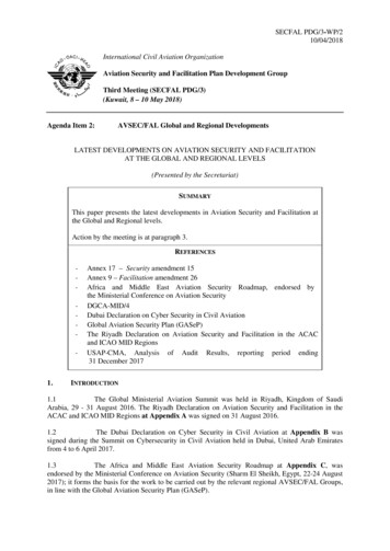
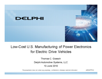
CHAPTER 1AIRCRAFT ELECTRICAL POWER SOURCESminute (rpm) determine the voltage frequency of thegenerator. With a fixed number of poles, constant frequency requires constant rotor rpm.As a technician, operating and maintaining variouselectrical power systems of modern naval aircraft, youmust be familiar with the operation of these systems.Electrical power requirements and electrical systemscomponents vary widely according to the size andapplication of the aircraft on which they are used.Aircraft electrical power sources are divided into twocategories: primary power sources and secondarypower sources.An ac generator-rotating field has 12 poles withadjacent poles of opposite polarity. Each pair of polesproduces one cycle per revolution; therefore, eachrevolution produces six cycles. The output frequency ofthe generator varies in direct proportion to the enginedrive speed. A generator operating at 6,000 rpm isoperating at 100 revolutions per second or at 600 Hz.AIRCRAFT PRIMARY AC POWERSOURCESPrimary power sources include main generators,inverters, and transformers. You must have a basicunderstanding of the components of these electricalsystems and power distribution systems in order tomaintain them in proper operating condition.The 120-/208-volt, 400-Hz, three-phase ac powersystem has many advantages over the 28-volt dcsystem. It requires less current than the 28-volt dcsystem because of higher voltage and a ground neutralsystem. The current required is a fraction of thatrequired for the same power in a 28-volt dc system.This permits the use of smaller aircraft wiring, savingweight. The ac generator and many of the system’scontrol and protection components are lighter. Twelvekilowatts is the practical limit to the size of an aircraftdc generator. Aircraft now have ac generators withratings up to 90 kilovolt-ampere (kVA).AC GENERATORSTypes of Ac GeneratorsAlternating current (ac) generators supply theelectrical energy for operating aircraft avionicsequipment. A generator is a machine that convertsmechanical energy into electrical energy by electromagnetic induction.Aircraft ac generators range in size from thetachometer instrument generator up to the 90,000volt-ampere generators. Generators are categorized aseither brush-type or brushless. Regardless of weight,shape, or rating, practically all of these generators havethe following common characteristics:LEARNING OBJECTIVES: Identify typesof primary alternating current (ac) powersources. Describe the construction of primaryac sources. Describe the characteristics ofprimary ac power sources.Ac power systems result in better design and use ofequipment than older electronic equipment powered bydirect current (dc), which have inverters for ac powerand dynamotors for supplying higher voltage dc power.These components are very heavy compared to theirrelative power outputs. They are not reliable andincrease maintenance costs and time. In today’saircraft, the same ac-powered equipment obtainsvarious ac voltages and dc power by using simpletransformers and transformer-rectifiers. These components are lightweight, simple, and reliable. The stator (stationary armature winding) provides the ac output. The ac generator field (rotor) is a rotating magnetic field with fixed polarity. Regulating the rpm of the rotating magnetic fieldcontrols the voltage frequency. Controlling the strength of the magnetic fieldregulates the voltage.Present military specifications require that thebasic aircraft ac power system produce voltage with avalue of 120 and 208 volts. A three-phase generator isactually three separate power sources enclosed in oneModern naval aircraft use the three-phase,120-/208-volt, 400-hertz (Hz) ac power system. Thenumber of magnetic poles and rotor revolutions per1-1
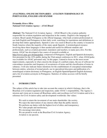
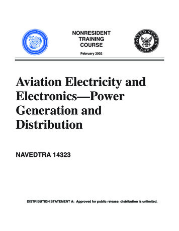
AC FIELDINPUT SPRING(5)housing (fig. 1-1(A)). To produce the required120-/208-volt output, external connections form a wye(fig. 1-1(B)). Each output winding produces 120 voltsas measured from n to a, b, or c (phase voltage). Whenmeasuring two separate phase voltages together (linevoltage), such as a to b, a to c, or b to c, the voltage is1.73 times the single-phase voltage, or 208 volts.EXCITERCOMMUTATOR(4)The line voltage found in a three-phase,wye-connected system is the vector sum of the voltagesgenerated by two separate phase windings. Because a120-degree phase difference exists between thevoltages, they reach their peak amplitudes at differenttimes. They add vectorially and not directly.AC POWEROUTPUTTERMINALSAC GENERATORSECTIONEXCITERDC GENERATORSECTIONAEf0102DRIVESHAFT(1)Figure 1-2.—Brush-type, three-phase ac generator.Look at figures 1-2 and 1-3 as you read this section.The exciter is a dc, shunt-wound, self-excitedgenerator. The exciter field (2) creates an area ofintense magnetic flux between its poles. When theexciter armature (3) rotates in the exciter-field flux,voltage is induced in the exciter armature windings.The output from the exciter commutator (4) flowsthrough brushes and slip rings (5) to the generator field.Being dc, already converted by the exciter commutator,the current always flows in one direction through thegenerator field (6). Thus, a fixed-polarity magneticfield is maintained in the generator field windings.When the field winding rotates, its magnetic flux passesthrough and across the generator armature windings(7). The ac in the ac generator armature windings flowsthrough fixed terminals to the ac load.120 VOLTS120 VOLTS120 VOLTS(A)EXCITER CONTROLTERMINALSbAC POWEROUTPUT TERMINALSACGENERATOREXCITERFIELDWINDINGS2208 VOLTS7753n2120 TATOR &SLIPRINGSECTIONBRUSH-TYPE.—Figure 1-2 shows a brush-typeac generator. It consists of an ac generator and a smallerdc exciter generator as one unit. The output of thegenerator supplies ac to the load. The only purpose forthe dc exciter generator is to supply the direct currentrequired to maintain the ac generator field. Figure 1-3 isa simplified schematic of the OLTERMINALSIn the four-wire, grounded-neutral, wye-connectedsystem, the neutral wire attaches to the frame of theaircraft (ground). The three-phase wires run to buses,which supply power to various loads. A bus is a primarypower distribution point that is connected to the mainpower source. The connections for loads requiring 120volts are between one of the buses and the aircraftframe. The load connections requiring 208 volts arebetween two of the buses (phases).AC FIELD WINDINGS(ROTOR)(6)AEf010164EXCITERARMATUREBRUSHES TORARMATUREWINDINGS(3-PHASE)AEf0103Figure 1-3.—Brush-type, three-phase ac generator schematic.Figure 1-1.—Three-phase ac generator output.1-2
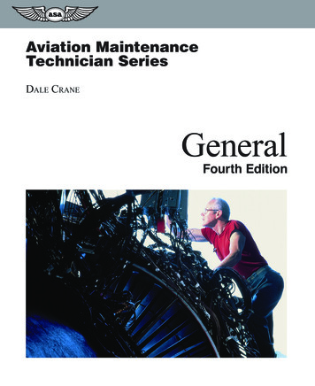
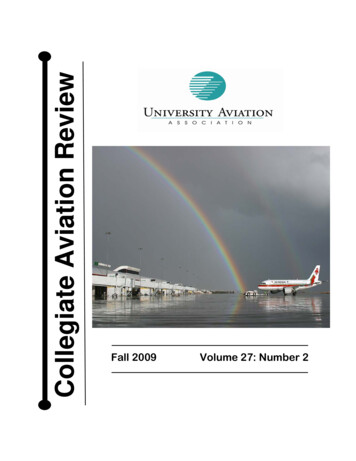
together, but also houses the PMG stator and thepermanent magnetic rotor core. The generator to airduct adapter allows a vent tube to be attached to thegenerator so that built-up air and fumes created by thespinning generator can be vented to the outside of theaircraft.The stationary member of the generator consists ofthe ac armature and the dc exciter field. Both ac andexciter terminal boards are easily accessible. All brushrigging is on the generator and has a brush cover. Theslotted-hole mounting provides for ease in attaching tothe engine pad. The capacitors connected between theexciter armature terminals and ground suppress radionoise.BRUSHLESS-TYPE.—Most naval aircraft areusing brushless generators for voltage generation. Theadvantage of a brushless generator over a brush-type isits increased reliability and greater operating timebetween overhaul. Figure 1-4 is an expanded view ofthe main assembly of a brushless generator.Some aircraft have oil-cooled generators. Theaircraft engine or gearbox oil enters the generatorthrough an inlet port and leaves through an exit port inthe mounting flange of the generator. As the oil passesthrough the generator, it absorbs the heat from the rotorand stator. At the same time, it cools the rotating seals,lubricates and cools the bearings, and is used for theconstant speed drive operation.The brushless generator shown in figure 1-4 is asalient 8-pole, 6,000-rpm, ac generator. It has a 12-poleac exciter and a three-phase, half-wave diode rectifierrotating with the exciter armature and main generatorfield assembly. The exciter rotor is a hollow frameassembly with the main ac field mounted on the insideand connected to a common drive shaft. A single-phasepermanent magnet generator (PMG) furnishes controlvoltage and power for the voltage regulator. Threehalf-wave rectifiers are on the exciter rotor andconnected to the exciter armature windings. Agenerator shaft shear section prevents possible damageto the engine or drive unit if the generator seizes. A fanat the drive end of the generator provides coolingairflow for the rotor and stator windings and the drivebearings. The end bell not only holds the generatorAs the generator shaft rotates, the PMG suppliessingle-phase, ac voltage to the voltage regulator andother protective circuits (fig. 1-5). PMG power isrectified and supplied to the exciter field. Theelectromagnetic field, built by the excitation currentflowing in the exciter, induces current flow in therotating three-phase exciter rotor. This current ishalf-wave rectified by rotating rectifiers. The resultantdc goes to the rotating field winding of the ac generator.The rotating electromagnetic field induces an acvoltage in the three-phase, wye-connected, outputwinding of the generator stator. Varying the strength ofthe exciter stationary field regulates voltage. Using anintegral ac exciter eliminates the need for brusheswithin the generator, which minimizes radio noise inother avionics equipment.18567432109AEf01041.2.3.4.5.Stator AssemblyRotor and ShaftRotating Diode AssemblyExciter RotorEnd Bell6.7.8.9.10.PM Generator StatorPermanent Magnetic Rotor CoreGenerator To Air Duct AdapterFan AssemblyDrive Shaft AssemblyFigure 1-4.—Disassembled brushless ac generator.1-3
T1T3T2(CSD) units, air or gas turbines, and the constant rpmturboprop engine.STATOR WINDINGCBAThe hydromechanical CSD unit converts variableengine speed to a constant speed output. It holds thefrequency steady to within a few hertz of the desired400 Hz. Load and fault transients limits are within a380- to 420-Hz range. Air or gas turbine drives, whichget the air supply by using bleed air from the jet enginecompressor or from a separate compressor, aresomewhat smoother in operation and hold steady-statefrequencies to within 10 Hz. The constant rpmcharacteristic of the turboprop engine gives goodfrequency stability to the ac generator output. Thepropeller mechanical governor will hold the generatorfrequency to 400 4 Hz.FEEDERFAULTCURRENTTRANSFORMERDT0ALTERNATOR FIELDEXCITERROTORWSWITCHEXCITERFIELDF1F0Q1-1. What are the advantages of using transformers and transformer rectifiers viceinverters and dynamotors for supplying aircraft power?PMPGGENERATORAEf0105Q1-2. What power system requirements do modernnaval aircraft have?Figure 1-5.—Sectional schematic of a brushless ac generator.Q1-3. What determines the voltage frequency of anac generator?Two three-phase differential transformers provideprotection against shorts in the feeder lines between thegenerator and the bus (called feeder fault). Onetransformer is on the generator (fig. 1-5). Its coils sensethe current flow through each of the legs that connectthe ground side of the generator stator to ground. Theother transformer is at the main bus and senses currentflow through the three feeder lines. A short in the feederline would cause the transformers sensing a differencein current to trip the generator off line.Q1-4. What are the two types of ac generators?Q1-5. What supplies the output ac power of a generator?Q1-6. How many phases is an ac generator?Q1-7. What are the advantages of a brushless generator over a brush-type generator?Q1-8. What is a prime mover?A generator mechanical failure warning device isincorporated in the generator. It consists of a softcopper strip embedded in and insulated from thegenerator stator assembly. A bearing beginning to failallows the rotor to rub against the copper strip,completing a warning light circuit to ground.Q1-9. What is the purpose of a CSD?INVERTERSInverters are an emergency source of ac powerwhen normal ac power fails. The backup system of theF/A-18 aircraft is an example of this type. The standbyattitude indicator receives power from the right115-volt ac bus. If the aircraft’s generators fail tosupply power to this bus, the standby attitude indicatorreceives power from an inverter. Because of a widevariety of inverters in use on aircraft, only one isdiscussed in this NRTC.Prime MoversA device, such as an aircraft engine, that providesthe driving force for a generator, is a prime mover. Earlyattempts to control the rotor speed of ac generatorsusing variable-pitch propellers or slipping clutcheswere unsuccessful, and ac generator power was ofvariable frequency. As power requirements grew, itbecame necessary to furnish ac power at a constantfrequency, to save weight and improve performance.The constant frequency is obtained from constant speeddrives such as hydromechanical constant-speed driveInverters consist of a speed-governed dc motor, anarmature and brush assembly, and a permanent magnetinductor-type ac generator in one unit. The armatureand the permanent magnetic rotor mount on a commonshaft.1-4
The dc motor converts electrical energy intomechanical energy to drive the generator. The dc loadcurrent drawn by the motor depends on the ac load onthe generator. A speed governor, or pulsating dc currentthrough the field windings, controls motor speed. Asolid-state, on-off switching circuit provides thepulsating direct current. The speed of a dc motor isinversely proportional to the strength of the field, so, asthe motor speeds up, more current flows in the shuntwindings, reducing the speed. As the motor speed fallsbelow its normal value, less current flows in theshunt-field windings, and the motor speeds up.The standard inverter is a 120-volt, three-phase,four-wire, 400-Hz ac system. The four-wire system isbetter than the three-wire system. It allows a greaterchoice of single-phase circuits, improves phase loadbalance, decreases vulnerability to power failure, andgives better frequency and voltage control.In most inverters, the dc armature and the acgenerating field windings are on the same rotor shaft.The dc motor field and generator output (armature)windings are on the stator. A control box on the invertercontains the necessary devices to control the inverter’soperation. These devices consist of the operatingrelays, voltage regulator and rectifier, filtering units,and smaller circuit components.The generator ac voltage is proportional to thespeed of the rotor and the strength of the generator rotorfield flux. The controlled frequency of the ac output isusually 400 Hz. This frequency is a function of thenumber of poles in the generator field and the speed ofthe motor. The number of sets of generator statorwindings determines the number of independentvoltages, or phases, in the output. Some inverterssupply both three-phase and single-phase outputs.Figure 1-6 shows a typical inverter.The dc motor of most aircraft inverters isessentially a shunt-wound motor. High starting currentand a low rate of acceleration (due to low torque atstarting) are characteristic of shunt-wound inverters. Toavoid these undesirable effects, the larger inverters havea series-starting winding. When the inverter reaches itsrated speed, relays disconnect the series-startingwinding and connect the dc input to the dc motorarmature and the shunt winding. The inverter thenoperates as a shunt-wound motor with constant-speedcharacteristics. Other inverters use small compensatingand commutating pole windings in series with themotor armature. These windings have no effect on theshunt-motor action.The rating of aircraft inverters varies depending onthe equipment that it supplies. For example, an aircraftmay carry a number of inverters. One inverter maysupply 120-volt, three-phase ac to an essential busduring emergencies. Another inverter supplies120-volt, single-phase ac power, while anotherAEf0106Figure 1-6.—Typical aircraft inverter.1-5
Transformer-Rectifiersfurnishes 120-/208-volt, three-phase power to aspecified bus or equipment. Figure 1-7 shows acutaway view of an inverter.Ac-powered equipment is more efficient than thelarger, heavier dc-powered equipment. Therefore, acgenerators now power naval aircraft; but dc power isneeded for lighting and for controlling ac-poweredequipment. The most common device now usedto provide the necessary dc voltage is thetransformer-rectifier (TR).Controlling the dc excitation current in thegenerator’s rotating field maintains the inverter outputvoltage at a constant value. Demand variations on theinverter output determine the strength of the dc rotatingfield.Inverters operate on the same electrical principlesas dc motors and ac generators. For detailedinformation about a particular inverter, refer to themaintenance instruction manual (MIM) covering thatinverter.TRs have no moving parts other than a cooling fan.A separate voltage regulator is not necessary as long asthe ac input voltage maintains reasonable limits. Dccurrent capability is high and is largely dependent onthe cooling available.Figure 1-8 shows an electrical schematic of atypical transformer-rectifier. You should refer to it asyou read this section. It requires a 120-/208-volt,three-phase, four-wire input at 400 Hz. It has an outputcapability of 200 amperes at 25.5 to 29.5 volts.TRANSFORMERSA transformer, by itself, is not a true electricalpower source. A true electrical power source canproduce electrical energy from another type of energy,such as chemical or mechanical. Transformers takeelectrical energy in the form of an ac voltage andconvert it to a different usable ac voltage.The input ac voltage enters through pins B, F, and Iand enters a radio frequency (RF) filter. The filterreduces noise interference to other avionics equipment651278910431112 1314151621 2017191.2.3.4.5.CommutatorBearing BracketArmatureHousingStator Core6.7.8.9.10.RotorBearing BracketSlip RingsInsulator BushingSpeed GovernorBrushesFigure 1-7.—Cutaway view of an E1616-2 inverter.1-616.17.18.19.20.21.Brush HolderScrewsPole ShoeField CoilCommutator Brush HolderCommutator Brush
ECR1-CR12T1HL1AFC1IC2T2BC3DCJ1TB1L2GS1 B1C4 C5-AEf0108Figure 1-8.—Schematic diagram of a typical transformer-rectifier.units. These savings are greatest when the turn ratio isless than 2:1 (either step-up or step-down). Savingsdiminish to insignificance when the turn ratio increasesbeyond 8:10. There is no isolation between primary andsecondary positions of the circuit, a feature that issometimes objectionable.in the aircraft. Power then connects with thewye-connected primary of a step-down powertransformer. The ac output of the wye, delta-connectedsecondary is rectified by diodes CR1 through CR12.The output goes through interphase transformer T2 anda filter network consisting of L2, C4, and C5 to the load.Interphase transformer T2 has an adjustable center tapto balance the two delta transformers for equal currentoutput. The filter network reduces the 4,800-Hz ripplevoltage to nearly straight-line dc voltage.Figure 1-9 shows a 2:1 step-down autotransformercircuit. The tap at point B divides the winding into two100VOLTSAutotransformersThe autotransformer is like an ordinarytransformer, except that it has one winding that iscommon to both primary and secondary windings.Within the limits of its application, autotransformersoffer savings in both size and cost over conventional5 AMPSAB5 AMPSFan motor B1 is connected in parallel with thepower transformer primary. This fan motor is essentialto proper operation and provides the only moving partsof the transformer-rectifier. Thermostat (S1) providesdetection of excessively high temperatures and, inconjunction with external circuits, turns on an overheatwarning light and automatically disconnects the input.SECONDARY PRIMARY5 AMPS5 AMPS10 AMPSDLOAD5 OHMS50VOLTSCE10 AMPSAEf0109Figure 1-9.—A 2:1 ratio autotransformer.1-7
There are many different uses for autotransformers.An autotransformer with a continuous variable tap,called a variac, is used where a continuous control fromzero to full (or even above) line voltage is necessary. Inthis case, the core is in the form of a ring toroid. Thewinding is usually in the form of a single layer coveringalmost the entire surface. A control shaft carries an armand a brush that makes contact with each turn of thewinding as the shaft rotates. The setting of the shaftdetermines the turns ratio. One end of the winding goesto both line and load, and the other end goes to the line.The brush connects to the other side of the load. Toobtain voltages higher than line voltage, the primaryconnects to a tap about 10% down from the end of thewinding. (Voltages higher than line voltage compensatefor abnormally low line voltage.) This providessecondary control from zero to full line voltage, eventhough the actual line voltage is as much as 10% belownormal.equal parts. With a load of 5 ohms connected as shown,compute the load current where I is current, E isvoltage, R is resistance, and P is power using theE50formula I or 10 amperes. The power in theR5load equals EI (50 10) or 500 watts. Just like a regulartransformer, this power comes from the primary by themagnetic field. Disregarding losses, the primary musttake 500 watts from the line. Therefore, the primaryP 500 or 5 amperes. Only thecurrent would beE 100 difference between these two currents, 5 amperes,flows in the common portion C to B (shown by thearrow). When the turn ratio is 2:1, the current in bothsections of the winding is the same. This saves the costand weight of an entire winding.The autotransformer in figure 1-10 has a turns ratioof 1.33:1. It connects to a load that draws 20 amperes.This represents a secondary power of EI (90 20) orP 1,800 or1,800 watts. The primary current equals E 120 15 amperes. The current in the winding from B to Ccommon to both circuits is the difference between theprimary and secondary line currents, or 5 amperes. Thesavings here are obvious. A conventional transformerwith the same characteristics requires a 120-volt,15-ampere primary and a separate 90-volt, 20-amperesecondary. Here, the requirement is a 30-volt,15-ampere winding in series with a 90-volt, 5-amperewinding. Thus, a 0.45-kVA autotransformer suppliesthe 1.8-kVA load.Instrument TransformersUsually, meters are not connected directly tohigh-voltage and high-current ac circuits. Instrumenttransformers connect meters to these circuits. Thesetransformers are of two general types—the current andthe potential. They permit the use of standardlow-voltage meters for all high-voltage or high-currentac circuits. They also protect the operating personnelfrom the high-voltage circuits.15 AMPSQ1-10.What are inverters?Q1-11.In an inverter, what converts electrical energyto mechanical energy?Q1-12.On what does the rating of an aircraft inverterdepend?Q1-13.What is the purpose of a transformer?Q1-14.What is the function of a transformerrectifier?Q1-15.What is the only moving part in a transformerrectifier?Q1-16.What is the difference between an autotransformer and an ordinary transformer?Q1-17.Autotransformers offer savings in both sizeand costs over conventional units. When arethese savings greatest?Q1-18.What are the two general types of instrumenttransformers?A20 AMPS120VOLTS5 AMPSB15 AMPSD90VOLTSCLOADE20 AMPSAEf0110Figure 1-10.—A 1.33:1 ratio autotransformer.1-8
Table 1-1.—Electrical Requirements for an Inertial Navigation SystemDC VOLTAGESAC VOLTAGES 45 V transistor bias26 V, 400 Hz-45 V transistor bias140 V, 400 Hz, three phase 28 V unfiltered and unregulated90 V, 375 Hz, three phase 28 V transistor bias12.6 V, 400 Hz 20 V transistor bias6.3 V, 400 Hz 10 V reference-10 V referenceTable 1-2.—Electrical Requirements for a Typical Transistorized Autopilot SystemPhase APhase BPhase CDC120 Vac120 Vac120 Vac28 V filtered45 Vac26 Vac15 Vac28 V unfiltered26 Vac15 Vac10 Vac19 Vac15 Vacexample, an inertial navigation system may require thevoltages shown in table 1-1. The voltages required byan AFCS in the same aircraft are shown in table 1-2.Obviously, one simple electrical power source will notprovide all the needed power for 20 or 30 avionicssystems.AIRCRAFT SECONDARY POWERSOURCESLEARNING OBJECTIVES: Identify typesof secondary power sources. Describe the construction of secondary power sources. Describethe characteristics of secondary power sources.Describe the operating principles of secondarypower sources.Normally, each avionics system has its own powersupply. Figure 1-11 shows the power supply for atypical autopilot system. The power supply require-Secondary power sources include electronic powersupplies, and emergency/backup power sources such asemergency generators, batteries, and external powersupplies. Many of the electrical and electronic systemsin naval aircraft require precise voltages to operate;therefore, each of these systems has its own powersupply. These power supplies come in many differentshapes, sizes, and designs, but all operate basically thesame way. The power supply discussed in the next fewparagraphs is typical of what is used on naval aircraft.ELECTRONIC POWER SUPPLIESIn high performance aircraft, avionics systems helpthe pilot communicate, navigate, or fire missiles. Othersystems, such as radar and autopilot (AFCS), ease thepilot’s workload. Each of these systems requiresprecision voltage inputs for proper operation. ForAEf0111Figure 1-11.—Typical electronic power supply.1-9
A0C0C0 115VA0 115VPITCHT4A0 45VA0 19VA0 15VNEUTRALB0 15VB0 26VB0 115VB0C0C0C0A0A0B0A0 115VA0C0A0 115VROLLT5A0 45VA0 26VA0 19VA0 15VA0 7VNEUTRALC0 10VC0 5V45V26V19V7VNEUTRALC0 10VAEf0112Figure 1-12.—Developing ac voltages for the autopilot.The circuit shown in figure 1-14 develops precisiondc voltages. Diode CR1 is a Zener diode that develops aconstant dc voltage at the input of amplifier A1,regardless of input voltage fluctuations. If the dc inputvoltage at the top of R1 increases, CR1 will conductharder; the excess voltage drops across R1. If thevoltage decreases, CR1 conducts less; less voltagedrops across R1. This maintains the voltage at theanode of CR1 at a constant, precision potential.ments (table 1-2) are for a 120-/208-volt, three-phase,four-wire, 400-Hz electrical power input. Look at theschematic shown in figure 1-12. Autotransformers T4,T5, and T6 produce the majority of the output voltages.The autotransformers have taps from each transformerwinding at the proper position to produce the requiredvoltage. Under fairly constant load conditions, nofurther voltage regulation is necessary.Full-wave rectifiers (fig. 1-13) produce dc voltages.Each pair of rectifiers (either CR7 and CR10 or CR8and CR9) conducts during alternate half cycles of the acinput from the secondary coil of step-down transformerT7. The unfiltered dc provides power to operate lightsand relays fo
AIRCRAFT ELECTRICAL POWER SOURCES As a technician, operating and maintaining various electrical power systems of modern naval aircraft, you must be familiar with the operation of these systems. Electrical power requirements and electrical systems components vary widely according to the size and application of the aircraft on which they are used.