Transcription
Valvoline FLUIDANALYSIS PROGRAMSM
What Can The Fluid Analysis Program Do For You?FLUIDVALVOLIBenefits include: Identify minor problems before they become major failuresEN Optimize oil drain intervals* Provide back-up for warranty claims entralized Global data base with Web access, can monitor informationCinternationally Regional Labs Across The U.S. Ensure Rapid Sample Processing E-Mail Alerts Provide Immediate Indication Of Potential Concerns Online Portal For Oil Sample Data, With Tools For Report Generation And Data Analysis Ongoing Assistance Available From Valvoline Application EngineersASALY ISNThe Valvoline Fluid Analysis Program is a monitoring and preventative maintenance service, designed to help our customers gain additional insight into equipment condition.This service gives vital information about the health of your equipment can helppredict and prevent catastrophic failure.When using Valvoline’s Fluid Analysis program, you can be confident that the test results are accurate, repeatableand performed to consistent methodologies and interpretation, whether the sample was processed in WesternUSA, or Western Australia. All Valvoline analysis laboratories provide consistent, global support, testing anddiagnostic interpretation.CF-2439-A 2012 Ashland Printed in U.S.A. 11/12 Trademark, Ashland and its subsidiaries, registered in various countries* Fluid analyses are one supporting component of a comprehensive maintenance program.Equipment manufacturer(s) should be consulted for specific recommendations regarding maintenancepractices, including (but not limited to) fluid drain intervalsVisit us at www.valvolinehd.com or call us at 1-800-354-9061.Learn more about all of our full line of Off-Road, On-Highway and Industrial products at www.valvolinehd.comor phone 1-800 354-9061 to put the Valvoline Advantage PERFORMANCE and PROTECTION to work for you.
FLUIDAVALVOLISALY ISNENResults and InterpretationValvoline’s Fluid Analysis program offers our customers agreat deal of flexibility in the delivery and management oftheir data. We can transmit reports via e-mail, provide accessto our Valvoline Fluid Analysis web-site to view and manage dataor send a data file that can be imported into other software programs.Reference GuidesMany times, users that test their in-service lubricants willlook at reports and ask “what do these tests mean?” Mostroutine analysis reports display similar test parameters formonitoring the condition of the operating equipment and thelubricant in service. This simple guideline will help explain the use andmeaning behind the routine tests you are likely to see on an analysis report.Please note that this serves only as a guideline; the elements listed do notpurport to include all possible resources.Valvoline Fluid Analysis has a full suite of management reports and datamining capabilities to assist you with improving and managing your maintenance programs.Searching for information based on a compartment type and/or othervariables is easy and quick through Valvoline’s global web portal. Webusers are able to assess compartments by problemand number of occurrences to aid in root causeanalysis. This application allows your organizationto review, e-mail and print reports, print samplelabels and run various management reports. Thesystem is easy to use and allows for numerouslevels of access and data viewing permissions.Physical and Chemical Tests for Lubricant Condition and Service LifeViscosity: Improper viscosity can affect a lubricants performance. T oo low of a viscosity will not create sufficientsurface film to keep moving parts separated andprevent rubbing on opposing metal surfaces. T oo high of a viscosity will create excessive heatand reduced fluid flow within circulating systems. A change in viscosity will indicate a change inthe fluid performance integrity. A drop in viscositygenerally indicates contamination with a lighterproduct, addition of an incorrect viscosity grade,and in some cases thermal cracking. An increase inviscosity can indicate oxidation and reduced servicelife due to age, addition of an incorrect viscositygrade, or excessive soot or insolubles ngsBushingsCompressor PistonCylinder / LinersClutch DiscsEngine After CoolerGearsHousing/BlocksHydraulic CylindersHydraulic PumpsOil CoolerPistonsPiston Skirt OverlayRingsRustShaftsThrust PlatesThrust WashersTurbine BladesValve Guides/StemValve TrainsWashersV)(Ti)m(diuVanaiumTitaner(Ag) SilvTin(Sn)(NikelNicb)d (PLea)))(FeIron(Cu(CrperCopiumromChminAluWhen trace elements are detected, the followingareas could be responsibleum(Al))Wear Metal Reference Guide
Titanium(Ti)(Zn)Calcium(Ca)Magnesium( Mg)Molybdenum(Mo)Phosphorus (P)Sodium(Na)Silicon(Si)(B)Boron(Ba)BariumPurpose of lubricant additiveAntimony(Sb)ZincLubricant Reference GuideAlkalinity ReserveAnti-foamAnti-wearAnti-oxidantCorrosion InhibitorDetergencyExtreme PressureFriction ModifierLubricityRust InhibitorWater SeparabilityBase Number: Base number provides a relative measure of alkalinityreserve available for neutralizing acids formed during the combustionprocess. As the lubricant ages and the additive package depletes, the basenumber will decrease from its initial fresh oil value. As there are variousmethods for measuring base number, caution should be exercised whencomparing results from different labs.CF-2439-B 2012 Ashland Printed in U.S.A. 11/12 Trademark, Ashland and its subsidiaries, registered in various countriesAcid Number: Acid number in a new lubricant represents a certain level ofadditive compounding. This can come from antirust, antiwear or other additives. The acid number can drop a bit after a lubricant has been in servicefor a certain period, which indicates some initial additive depletion. After atime the acid number will start to increase, which indicates the creation ofacidic degradation products related to Mg)Ma(B)onBorAluWhen contaminants are detected,the following could be the sourceAftercooler Grazing FluxCoolantDirtGasket/Seal MaterialNatural Gas (Wet Gas) TransferringSeawaterminum(AI)Contaminant Reference GuidePhysical and Chemical Tests for Lubricant ContaminantsWater: Water as a contaminant will generally lead to increased corrosion,depletion of proper lubricating film, decreased lubricant performance lifeand increased acid formation.Coolant: Coolant contamination will degrade lubricant service life andperformance, create sludge and block lubricant passageways.Fuel Dilution: Fuel dilution will decrease fluids viscosity, therefore affectingits lubricity properties. Fuel dilution also promotes degradation of lubricantservice life and additive properties.Soot: Excessive soot increases viscosity, creates excessive wear, and willtie up active additives needed for lubricant performance.Oxidation Number: The oxidation number is a relative number that monitorsincrease in the overall oxidation of the lubricant by infrared spectroscopy.This test parameter generally complements other tests for fluid service life,such as viscosity and acid number. Generally this test is not used as a primaryindicator when all other tests are within normal limits. Accurate oil informationis required to get the most valid test results.Particle Count: “Clean Systems” require a minimum level of cleanliness inorder to operate reliably. This is especially true for circulating systems withhigh pressure and close tolerance components. The ISO Cleanliness Ratingis a convenient way to communicate the level of particulate contaminationwithin a system based on the particle count for micron sizes greater than4, 6, and 14.Nitration Number: The nitration number is a form of oxidation that relatesto chemical reaction with nitrogen, forming nitrogenous compounds also.Nitration is a relative number that monitors increase in the overall fluid degradation due to reaction with nitrogen and oxygen by infrared spectroscopy.This test parameter generally complements other tests for fluid servicelife, such as viscosity and acid number. Generally this test is not used asa primary indicator when all other tests are within normal limits. Accurateoil information is required to get the most valid test results. Contributors toincreased nitration can come from exhaust gas blow-by or reaction withnatural gas products with the lubricant and heat. It is also an indicator ofelectrostatic discharge across filter surfaces in turbine oil.Tests for Wear DebrisParticle Quantification Index (PQI): PQI is a valuable trending tool for monitoring the relative level of ferrous wear material within a lubricant sample.Filter Patch: Filter patch inspection provides a visual assessment of wearparticle and other solid debris present in a sample after collection on a 0.8micron to 5.0 micron filter membrane and examined by a microscope.Microscopic Particle Examination (MPE): Analytical Ferrography providesdetailed information on different wear particles present in a sample. This isgenerally an exception test that provides information on the type of metalmakeup of the wear particles present and how they were formed.
Test DescriptionLevel VIII Basic AnalysisLevel IX Advanced Coolant Analysis)Elem(ICP ent AD5 naly185 sis)Water%or FT by CWK IR, po racklF (E sitiv e203 e/D6Vis304cos)(D4 ity @45)40 CViscosi(D4 ty @45)100 CFuelD(D3 ilutio5Set 24 GC n %aFla or DFue sh Po 3828int)l(Wi Sootlks %SootMTANete(D6r)64)TBN(D4739)TBN(D2896Oxi)da(E2 tion/412 Nitratio)nISOPar(ISO tic115 le C00/ ount4406)VALVOLIFLUIDLevel I Basic Analysis NonEngine Engine Engine EngineLevel II Extended Drain NonEngine Engine Engine Engine NonEngine EngineLevel III Extended Drain Comprehensive NonEngine Engine Engine Engine NonEngine EngineTotal(D1 Disso125 lve, m d Soodi lidsCarfiedbox)Cum ylatula e AciCon tive dcen Pertrat cenion t(UPLC)(D3321Ele)mby ental MICP(D5 etals185Fre)ez(Re e Poinfrac ttometeGlyr)col(Re %fractometer)Nitrate(D5827)Nitriteor (D5Titr 82atio 7n)pH(D1287)intl PoBoientssmLevel VII Technical Service PackageA ppe(Vis arancual eAsseTest PackageSALY ISNENAAnalysis and Sampling Supply OptionsLubricantsLevel IV Natural Gas EngineLevel V Advanced Natural Gas EngineLevel VI Hydraulic (D203/D6304)Coolants
Sampling SuppliesSampling SuppliesInventory Item DescriptionPART NUMBERC-PPDLBLC-VKP141/4" KP Pushbutton Valve - recommended for pressurized systems (5-3000psi), maxsample pressure 750psi. Suitable for engines, transmissions, compressors and in-linehydraulicsC-VKP181/8" KP Pushbutton Valve - recommended for pressurized systems (5-3000psi), maxsample pressure 750psi. Suitable for engines, transmissions, compressors and in-linehydraulicsC-PUMPSuction Dual PumpC-TUBING100' Roll of Tubing (precut is also available)VB141/4" B Series Valve - recommended for pressurized systems (5-3000psi), maxsample pressure 750psi. Suitable for general industrial, plant and utilityPROBEB14Probe Adapter for use with the B Series Valve. Designed to transfer between valves/remove after sampling. (Tubing also required for use with Adapter)VK18CF-2439-C 2012 Ashland Printed in U.S.A. 11/12 Trademark, Ashland and its subsidiaries, registered in various countriesPostage Paid Return Mailing Labels1/8" KST Series Valve - recommended for vacuum systems, pressurized systems(5-3000psi), max sample pressure 750psi. Suitable for general off-highway, mobileand marine applicationsCAPPROBENeedle probe samplyzer, for use with needle port valves and required with the KST ValveLT Tube ExtenderLT High Flow tube extender for non-pressurized and low pressure systems. Use for splashlubricated gearboxes and bearings, etc. Steel tube positioned permanently inside to drawconsistent representative samples. (For use with adapter)VLT14NT121/4" OD Probe adapter for L/LT valve fittingOTHER SUPPLIES AVAILABLE. CONTACT US FOR A FULL LIST.
VALVOLIFLUIDASALY ISNENTake a SampleEquipment manufacturers provide recommendations for preventative maintenance practice, but how critical a piece of equipment is to productivityshould be a major factor in determining sample frequency. High temperatures, dirty operating conditions, short trips, heavy loads and excessiveidle times can significantly affect the optimum sample frequency.For Optimum Results Determine optimum sample schedule Identify sample points and take samples from the same point each time Take sample while the machine is at normal operating conditions or immediatelyafter shut down Utilize storage and handling best practicesGeneral Guidelines for Taking a Quality SampleEach sample drawn must be taken regularly from a single location in a system. Take samples during normal operating conditions, downstreamof pumps, cylinders, bearings, and gearboxes and upstream from the filter. When obtaining a sample from a lubricated system, always have theoil hot and thoroughly mixed before sampling. When possible and safe, always take the sample while the machine is running. Make sure that the sample bottle is clean and free of any moisture before obtaining sample. When utilizing the vacuum pump method, make sure that sample is not obtained from the bottom of the oil compartment where sludgeaccumulates. Aim for the midpoint of the reservoir. Obtain samples during normal equipment operation or at least within 30 minutes after equipment is shut down. This is the best way toobtain a truly representative sample of conditions within a lubricated compartment or a machine compartment. Make sure that sample bottle and container are properly sealed before shipping. Fill out the sample information form correctly and completely. Ship sample to laboratory promptly to receive analysis results as soon as possible.Sample Valve MethodInstall valves upstream of any filter in order to capture wear particles. Make sure the valve isclean and adequately flushed. Using a sample valve, such as the 1/8” NPT Push Button Valve,helps in producing reliable test results. Install valve properly on a pressurized oil line or oil galley.Avoid areas where oil does not circulate as freely, such as the bottom of a sump.1.Unscrew dust cap from sample valve.2.Depress the button on the sample valve.3.Flush the oil line allowing several ounces to drain before taking the sample.4.Place the empty sample bottle under the sample valve discharge opening.5.Fill the sample bottle 3/4 full and release the sample valve.6.Tighten the cap on the sample bottle to secure a tight seal.7.Screw the dust cap back on the valve. Prepare for shipment.
Sample Pump MethodIf taking an oil sample using the pump method, operate the equipment long enough to mix the oil thoroughly; bringing the oil to operating temperatureis a good indication that the oil is adequately mixed. It is important that vacuum pumps are used with appropriate tubing. Make sure that new tubing isused for each sample in order to avoid cross contamination. Cut the tubing to the same length each time you sample. Avoid scraping the tubing alongthe sides or bottom of the tank or reservoir. Use this method with systems not equipped with sampling valves.Taking an Oil Sample Using the Pump Method:1. The objective is to insert the tubing into the sump at the same depth as the tip of the dipstick. Measure and cut new tubing to thelength of the dipstick PLUS the amount required to comfortably position the vacuum pump for sample extraction (a common rule ofthumb is to add about 6” to the length of the dipstick, but this may vary according to the position and accessibility of the dipstick tube2. Insert the tubing through the head of the vacuum pump and tighten the retaining nut. The tubing should extend about 1/8 inch beyondthe base of the vacuum pump head.3. Install a new sampling bottle onto the vacuum pump and insert the end of the tubing into the oil – do not allow the tubing to touch thebottom of the compartment.4. Pump the vacuum pump handle to create a vacuum. Hold the pump upright to avoid oil from contaminatingthe pump. If oil enters the pump, disassemble and clean it before taking the sample. Fill the oil sample bottle at least 3/4 full.5. Remove the tubing from the compartment and dispose of it correctly. Do not reuse tubing. Remove the bottle from the vacuum pumpand secure the cap on the bottle. Prepare for shipment.Drain Line MethodThe drain line method is considered the least preferred method of sampling. If used, make surethat an ample amount of oil is drained before collecting a sample. The sludge, particles and waterthat settle to the bottom of a tank or reservoir provide poor and sometimes unreliable results.Taking an Oil Sample Using the Drain Method:1.Clean area around the drain plug to avoid sample contamination.2.Allow ample amount of oil to flush through the oil pan drain hole.3.Fill sample bottle 3/4 full.4.Screw bottlecap on tightly. Wipe bottle clean and prepare for shipment.Proper identification from each unit sample is crucial for tracking critical reports and unusual wear.Each sample submitted to the designated laboratory should include a Sample Information Form (SIF).CF-2439-E 2012 Ashland Printed in U.S.A. 11/12 Trademark, Ashland and its subsidiaries, registered in various countriesSample Identification Forms (SIF)Keep in mind that the laboratory cannot perform accurate analysis and interpretation, unlessthey have all the information required on the Sample Identification Form properly filled out.
VALVOLIFLUIDASALY ISNENLaboratories and ServicesAll Valvoline Fluid Analysis laboratories are able to assist our customers with new customer set up, equipment registration, sampling kits and equipment and othergeneral questions.Global map of locations and contact address/phone and faxUNITED STATESCANADA3121 Presidential DriveAtlanta, GA 30340Tel: 800.394.3669Fax: 770.451.1500935 Sunshine RoadKansas City, KS 66115Tel: 800.332.8055Fax: 913.281.98851240 Burloak Drive Suite 6Burlington, ON L7L 6B3 CanadaTel: 877.732.9559Fax: 905.632.93041375 Greg Street, Suite 104Sparks, NV 89431Tel: 800.524.7848Fax: 775.358.38714943 NW Front AvenuePortland, OR 97210Tel: 800.770.4128Fax: 503.286.156210717-176 StreetEdmonton, Alberta T5S 1K1Tel: 888.489.0057Fax: 780.486.225718419 Euclid AvenueCleveland, OH 44112Tel: 800.726.5400Fax: 216.383.96333319 W. Earll DrivePhoenix, AZ 85017Tel: 800.445.7930Fax:602.252.4639To order sampling supplies, please contactyour local Valvoline representative, or e-mailus at Vavoline@alsglobal.com
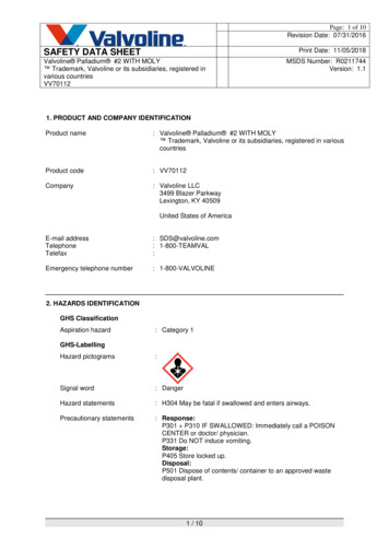
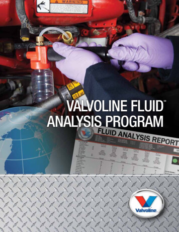
CF-2439-F 2012 Ashland Printed in U.S.A. 11/12 Trademark, Ashland and its subsidiaries, registered in various countriesExample Of Fluid Analysis Report
CF-2439-G 2012 Ashland Printed in U.S.A. 11/12 Trademark, Ashland and its subsidiaries, registered in various countries
FLUIDAVALVOLISALY ISNENEngine Coolant Reference GuideClarityClearAppear hazy or opaqueColorClear, bright, andrepresentative of theoriginal engine coolant colorVisible SedimentNoneVisible Petroleum LayerNoneBrown could indicateimproper mixing ofdifferent coolantsPresence of sediment is typicallyindicative of additive fallout,corrosion, rust, scale buildup, orother contaminantsIndication of fuel or oilcontamination will beobserved usually in the form of aseparated layerionActtiverecCorObTargAppearance Assessmentseretva tionAppearancePossible ResultEngine coolants are a mixture of glycol, inhibitors, and water. Each formula is designed for specific protection and engine requirements. Mixingdifferent coolants is not recommended and can compromise the coolant’s general overall protective capability, resulting in decreased coolant lifeand damage to the cooling system and/or engine. The following is a reference guide to assist in understanding the engine coolant data.Degraded or contaminated enginecoolants or a mixture of incompatiblecoolant typesDecreased coolantprotectionWater pump and seal deterioration,liner pitting, copper and aluminumcorrosion, plugged oil cooler andradiator; poor sampling technique.Combustion gas blow-by into thecoolant, leaking oil cooler; poorsampling techniqueCheck shelf life of thecoolant; check coolant handlingpracticesVerify original coolant color of productin use; if brown was reported, checkcoolant handling practicesAdd a non-SCA filter for ELC coolants;add an SCA filter to conventionalcoolant systemsCheck for any seal failures andsystem integrityELC Engine Coolantand ConventionalEngine CoolantExtended Life 7.5 - 9.5 pHConventional 8.5 - 11.0 pHELC Low pH ( 7.5 )Conventional Low pH( 8.5 )ELC High pH ( 9.5);Low pH can lead tometal corrosionMixed coolant typesAir leaks will lower pHOver additized SCAconcentrationConventional High pH ( nHigLowhppHHpHCheck coolant volumeCheck for air leaksPressure check radiator capCheck SCA filter and replace ifneeded (conventional coolant only)Improper coolant volumeElectrical grounding issues (ifcoolant has a burnt smell)Shelf life of coolant,age will lower the pHCombustion gas leak if pH isbelow 7.0Under additized SCAconcentration(conventional coolant)Remove SCA filter when ELCcoolants are in use, this will addpH buffer and raise the pHDrain, flush, refill then resample
This can reduce heat transferproperties resulting in cavitationsand liner pittingTDS20000 maxvatserObObTargseretva tionLowionHighTDSConductivity / Total Dissolved Solids (TDS)Improper source water,over concentration of SCAsNormalActiontiverecCorConfirm bulk source of coolant forinadequate concentrationAdjust using Valvoline under orover concentrated chart andrecheck freeze point or resampleionImproper adjustmentwith waterPressure check radiator capActToo high indicates over use ofconcentrate or water is boiling offtiveConfirm adequate protectionrequirements for applicationCheck proper coolant volumesrecHigh Glycol ( 60 %)Freeze Point ( - 60 F)CorLow Glycol ( 40 % )Freeze Point ( -15 F )TDS40% to 60%ObsGly ervaticol onCon Higcen ht rationTargetGlycol ConcentrationPercent GlycolObsGly ervatcol ionCon Lowcent rationFreeze Point / Percent GlycolConfirm water source; distilled ordeionized is recommendedCheck for improper SCA filter drain,flush and refillNitriteInitial coolant concentrationtypically: 1200 PPMVerify coolant type in useOver concentration of glycolNitrite only formulas 300 PPM fornitrite/molybdate formulasImproper coolant mixing 25 for nitrite freeOver concentration of SCAsfor conventional coolantsActtiverecCorObseNit rvatiorite nHigsObsLowervatNit ionritesTargNitritesethionNitritesCheck the coolant mixture, if under or overconcentrated, this will impact the nitrite levelwhen presentIf low, look at nitrate level; if pH has dropped,check for head gasket leaks, low coolantvolumes, and pressure check radiator capRapid depletion could indicate overheatingof the cooling system and localized hot spots,check; this will occur along with an increasein glycolatesRapid depletion could also indicate electricalshorts; check grounding, coolant will havea burnt smellIf using ELC, check for a pre-charged SCA filter and replace with a non-pre-charged filterIf nitrites are low, but carboxylate acid inhibitor passed, resample at next service intervalDrain 50% of system and add 50/50coolant, resample
Passing level depends on the initialextended life coolant’s inhibitor ationCarboxylate AcidtionLowOAIHighOAICarboxylate Acid TechnologyVerify coolant type in useVerify coolant type in useUnder concentrated with glycolOver concentrated with glycolImproper coolant mixingImproper coolant mixingAdjust coolant concentration; if overconcentrated, add proper source water; if under concentrated, add glycolconcentrate; check freeze point andresample at next service interval 25 % diluted, adjust using OEMrecommended inhibitor packageIf the coolant was improperly mixedwith conventional and extended lifecoolant, significantly affecting theinhibitor level’s protection capability,either drain and flush or contact yourOEM for corrective actionCoolant is brown – possibleimproper conversion fromconventional to extended lifeOther Ion Chromatography DataIon Chromatography ResultsSourceChloridesOutside contaminants and can come from improper source water or air leaks. It has the potential to form acids and cause corrosion. It can also come fromcoolant degradation due to aging.GlycolatesIs among a group of acids that form as coolant degrades. This will also increase when overheating or hot spots are occurring. As this acid increases, ironcorrosion is at risk.MolybdateProvides protection of cast iron corrosion and cavitations.NitratesProvides protection of light alloys also provides aluminum and solder protection. If nitrites are being exposed to air, they will chemically transform tonitrate – when this occurs look for air leaks.PhosphatespH buffer utilized in some coolant brands and provides iron corrosion protection. Over treating the cooling system can lead to sediment detection resulting inpossible plugged oil cooler or radiator. Some engines that are aluminum must be phosphate free, check OEM requirements before using a phosphate coolant.SulfatesThis contaminant can combine with calcium to create scale. This can also indicate coolant degradation due to aging or improper source water is being used.Wear ElementsWater ElementsAdditional information and resources are available through the ALS Tribology eSource, our electronic newsletter.Visit http://esource.alstribology.com to view past issues of eSource or to register to receive this free electronic newsletter via email.(Zn))Additive ElementsZincn)Tin(S(NaAg)er (SilviumSodSi))(K)on (SilicPotassium(P)orussphm (MPhoenuium(MgybdMolnesMagb)d (PLea(Fe)(Cu(Ca))IronperCopB)iumCalcon (BorCoolant Spectrochemical DataAluminum(Al))o)Coolant Spectrochemical Data
CF-2439- or phone 1-800 354-9061 to put the Valvoline advantage PeRFoRManCe and PRoTeCTion to work for you. a 2012 a shland Printed in U.S. a. 11/12 Trademark, a shland and its subsidiaries, registered in various countries What Can The Fluid Analysis Program Do For You?