Transcription
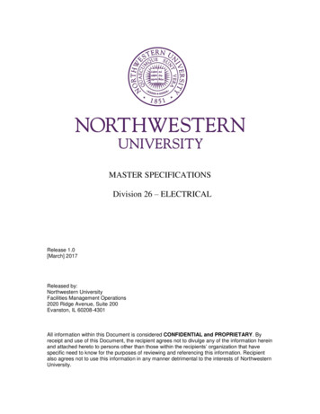
MASTER SPECIFICATIONSDivision 26 – ELECTRICALRelease 1.0[March] 2017Released by:Northwestern UniversityFacilities Management Operations2020 Ridge Avenue, Suite 200Evanston, IL 60208-4301All information within this Document is considered CONFIDENTIAL and PROPRIETARY. Byreceipt and use of this Document, the recipient agrees not to divulge any of the information hereinand attached hereto to persons other than those within the recipients’ organization that havespecific need to know for the purposes of reviewing and referencing this information. Recipientalso agrees not to use this information in any manner detrimental to the interests of NorthwesternUniversity.
Northwestern UniversityMaster SpecificationsCopyright 2017By Northwestern UniversityThese Specifications, or parts thereof, may not be reproduced in any form withoutthe permission of the Northwestern University.
NORTHWESTERN UNIVERSITYPROJECT NAMEJOB #FOR:ISSUED: 03/29/2017MASTER SPECIFICATIONS: DIVISION 26 – ELECTRICALSECTION #TITLE26 050026 0501COMMON WORK RESULTS FOR ELECTRICALGENERAL ELECTRICAL REQUIREMENTS FOR RENOVATION ANDDEMOLITIONMEDIUM VOLTAGE CABLESLOW VOLTAGE ELECTRICAL POWER CONDUCTORS AND CABLESGROUNDING AND BONDING FOR ELECTRICAL SYSTEMSHANGERS AND SUPPORTS FOR ELECTRICAL SYSTEMSRACEWAYS AND BOXES FOR ELECTRICAL SYSTEMSUNDERGROUND DUCTS AND RACEWAYS FOR ELECTRICAL SYSTEMSIDENTIFICATION FOR ELECTRICAL SYSTEMSCOMMISSIONING OF ELECTRICAL SYSTEMSMEDIUM VOLTAGE TRANSFORMERSLOW VOLTAGE TRANSFORMERSLOW VOLTAGE SWITCHGEARSWITCHBOARDSPANELBOARDSELECTRICITY METERINGWIRING DEVICESFUSESENCLOSED SWITCHES AND CIRCUIT BREAKERSENCLOSED CONTROLLERSENGINE GENERATORSCENTRAL BATTERY EQUIPMENTUNINTERRUPTIBLE POWER SUPPLYTRANSFER SWITCHESSURGE PROTECTIVE DEVICESINTERIOR LIGHTINGEXTERIOR LIGHTING26 051326 051926 052626 052926 053326 054326 055326 080026 120026 220026 230026 241326 241626 271326 272626 281326 281626 291326 321326 332326 335326 360026 431326 510026 5600** End of List **
NORTHWESTERN UNIVERSITYPROJECT NAMEJOB #FOR:ISSUED: 03/29/2017SECTION 26 0500 - COMMON WORK RESULTS FOR ELECTRICAL WORKPART 1 - GENERAL1.1SUMMARYA.(delete if not required) [It is intended this project pursue a LEED [Gold] [Silver] rating.LEED criteria will be followed for the installation of building systems. This Contractorshall be responsible for the following items to ensure the Facility achieves LEEDcertification:1.2.3.4.5.6.7.B.Section Includes:1.1.2SS credit 8 – Light Pollution Reduction.EA prerequisite 2 – Minimum Energy Performance.EA credit 1 – Optimize Energy Performance.MR credit 2 – Construction Waste Management.IEQ credit 4.1 – Low Emitting Materials: Adhesives and SealantsIEQ credit 4.2 – Low Emitting Materials: Paints and Coatings.IEQ credit 6.1 – Controllability of Systems: Lighting.]Common electrical installation requirements.SUBMITTALSA.N/A.PART 2 - PRODUCTS2.1N/A.PART 3 - EXECUTION3.1COMMON REQUIREMENTS FOR ELECTRICAL INSTALLATIONA.Comply with Northwestern University Design Guidelines.B.(Select based on project location) [Comply with City of Chicago Codes and Standards.][Comply with City of Evanston Codes and Standards.]C.Comply with NECA, NFPA, and OSHA requirements.D.All work shall be installed in a neat, workmanlike manner in accordance with ANSI/NECA 1 –2015.COMMON WORK RESULTS FOR ELECTRICAL WORK26 0500 - 1
NORTHWESTERN UNIVERSITYPROJECT NAMEJOB #E.All materials and equipment provided under this contract shall be new (except where otherwisenoted) and shall be listed, labeled or certified by a Nationally Recognized Testing Laboratory(NRTL) to meet Underwriters Laboratories, Inc. (UL), standards where test standards havebeen established. Materials and equipment which are not covered by UL standards will beaccepted, providing that materials and equipment are listed, labeled, certified or otherwisedetermined to meet the safety requirements of a NRTL.1.F.FOR:ISSUED: 03/29/2017A Nationally Recognized Testing Laboratory is a testing laboratory which is recognizedand approved by the Secretary of Labor in accordance with OSHA regulations.All materials, products, and equipment being installed which fall into a category covered by the ENERGY STAR program shall be provided and labeled as such.G.All equipment of the same type and capacity shall be by the same manufacturer.H.Keying: All panel doors in electrical equipment shall be equipped with Corbin Access Systemskey cylinders with removable cores. Coordinate with University Electric Shop.I.Where any device or part of equipment is referred to in these specifications in the singularnumber (e.g., "the switch"), this reference shall be deemed to apply to as many such devices asare required to complete the installation as shown on the drawings.J.During construction the contractor shall at all times maintain electrical utilities of the buildingwithout interruption. Should it be necessary to interrupt any electrical service or utility, thecontractor shall secure permission in writing from the University’s Chief Electrician for suchInterruption at least ten (10) business days in advance. Any interruption shall be made withminimum amount of inconvenience to the University and any shut-down time shall have to be ona premium time basis and such time to be included in the contractor's bid. Arrange to provideand pay for temporary power source as required by project conditions.K.Measure indicated mounting heights to bottom of unit for suspended items and to center of unitfor wall-mounted items.L.Headroom Maintenance: If mounting heights or other location criteria are not indicated, arrangeand install components and equipment to provide maximum possible headroom consistent withthese requirements and shall be coordinated with NU Electric Shop.M.Working clearance around equipment shall not be less than that specified in the N.E.C. for allvoltages specified.N.The locations of switches, receptacles, lights, motors, etc. outlets shown are approximate. Thecontractor shall use good judgment in placing the preceding items to eliminate all interferencewith ducts, piping, etc. The contractor shall check all door swings so that light switches are notlocated behind doors. Relocate switches as required, with approval from the DesignProfessional. The University may direct relocation of outlets before installation, up to five (5) feetfrom the position indicated on the Drawings, without additional cost.O.Equipment: Install to facilitate service, maintenance, and repair or replacement of componentsof both electrical equipment and other nearby installations. Connect in such a way as tofacilitate future disconnecting with minimum interference with other items in the vicinity. Normalmaintenance shall not require the removal of protective guards from adjacent equipment. Installequipment as close as practical to the locations shown on the Drawings.COMMON WORK RESULTS FOR ELECTRICAL WORK26 0500 - 2
NORTHWESTERN UNIVERSITYPROJECT NAMEJOB #1.2.FOR:ISSUED: 03/29/2017Where the University’s Chief Electrician determines that the Contractor has installedequipment not conveniently accessible for operations and maintenance, the equipmentshall be removed and reinstalled as directed at no additional cost to the University.“Conveniently Accessible” is defined as being capable of being reached without climbingor crawling over or under obstacles such as motors, pumps, belt guards, transformers,racks, piping, ductwork, raceways or similar.P.Right of Way: Give to piping systems installed at a required slope.Q.Firestopping shall be applied to electrical penetrations of fire-rated floor and wall assemblies torestore original fire-resistance rating of the assembly according to Division 07 and 09 Sectionsand the University Fire Protection Standards.R.Owner furnished equipment: Equipment furnished by the University shall be received, stored,uncrated, protected, and installed by the Contractor with all appurtenances required to place theequipment in operation, ready for use. The Contractor shall be responsible for the equipment asif he had purchased the equipment himself and shall hold the warranty.END OF SECTION 26 0500COMMON WORK RESULTS FOR ELECTRICAL WORK26 0500 - 3
NORTHWESTERN UNIVERSITYPROJECT NAMEJOB #FOR:ISSUED: 03/29/2017THIS PAGE IS INTENTIONALLY BLANKCOMMON WORK RESULTS FOR ELECTRICAL WORK26 0500 - 4
NORTHWESTERN UNIVERSITYPROJECT NAMEJOB #FOR:ISSUED: 03/29/2017SECTION 26 0501 – GENERAL ELECTRICAL REQUIREMENTS for RENOVATION and DEMOLITIONPART 1 - GENERAL1.1SUMMARYA.This Section includes general requirements for renovation and demolition of electrical systemsand materials for all Campus buildings and facilities.1.B.(Future use):1.1.2(Future use).(Future use).RELATED DOCUMENTSA.1.3Drawings and general provisions of the Contract, including General and SupplementaryConditions and Division 01 Specification Sections, apply to this Section.SUBMITTALSA.N/A.PART 2 - PRODUCTS2.1N/A.PART 3 - EXECUTION3.1REQUIREMENTS FOR ELECTRICAL RENOVATION AND DEMOLITIONA.Comply with Northwestern University Design Guidelines.B.(Select based on project location) [Comply with City of Chicago Codes and Standards.][Comply with City of Evanston Codes and Standards.]C.Comply with NECA, NFPA, and OSHA requirements, NEC-70 and -70E.D.The University may occupy portions of the building immediately adjacent to the area ofdemolition. Arrange demolition so as not to interfere with University's operations.E.Protect adjacent building services and materials indicated to remain. Install and maintainbarriers to keep dirt, dust and noise from being transmitted to adjacent areas. RemoveGENERAL ELECTRICAL REQUIREMENTS for RENOVATION and DEMOLITION26 0501 - 1
NORTHWESTERN UNIVERSITYPROJECT NAMEJOB #FOR:ISSUED: 03/29/2017protection and barriers after demolition is completed. If infiltration of dust or dirt results due toimproper barriers, Contractor shall be responsible for all maintenance and cleaning.F.Where electrical work to remain is damaged or disturbed in the course of the work, theContractor shall remove damaged portions and provide new products of equal capacity, quality,and functionality at his own expense.G.Unless otherwise noted, demolish and remove existing electrical materials and equipment onlyto the extent required by new construction and as indicated. Removal of equipment shall notinterfere with existing operations.H.Notify Architect of discrepancies between existing conditions and the Drawings beforeproceeding with demolition or renovation.I.During construction the contractor shall at all times maintain electrical utilities of the buildingwithout interruption. Should it be necessary to interrupt any electrical service or utility, thecontractor shall secure permission in writing from the University’s Chief Electrician for suchinterruption at least ten (10) business days (or two calendar weeks) in advance. Anyinterruption shall be made with minimum amount of inconvenience to the University and anyshut-down time shall have to be on a premium time basis and such time to be included in thecontractor's bid. Arrange to provide and pay for temporary power source if required by projectconditions. If requested by NU Electric Shop, power may be metered. Submit drawing ofproposed temporary connections for approval.1.2.3.Services passing through areas of remodeling shall be maintained throughout theconstruction period.Circuits serving areas adjacent to the construction area that are modified as part of aremodeling project shall be re-circuited as part of the project.Provide temporary and/or modify existing emergency power, emergency lighting, firealarm, and other services as required for construction-period Life Safety measures.Submit proposed plan to NU Electric Shop.J.Contractor shall ensure that light switches within the Work area remain operational. Wheretemporary 120 volt light strings are installed, a switch shall be provided for the light strings nearthe Project entry door. Lights shall be switched off every day at the completion of the shift.K.Turn off circuit breakers or switches serving abandoned circuits at the commencement of workand tag breaker or switch and label in panel schedule as “Spare”.L.Remove conduit and wire back to panelboards or to nearest junction box that is not beingremoved and needs to remain in service. Wire shall be removed back to point of origin.M.Conduit and Junction Boxes:1.2.3.4.N.Conduit and boxes in existing walls to be demolished shall be removed.Conduit and boxes in existing walls to remain (if not reused) shall be removed.Conduit in existing or new ceilings that is not intended for reuse shall be removed back tothe panel from where it originates.Conduits that had been run in existing slabs shall be saw-cut off flush where they exit theslab and then be fire-sealed.Conductors:GENERAL ELECTRICAL REQUIREMENTS for RENOVATION and DEMOLITION26 0501 - 2
NORTHWESTERN UNIVERSITYPROJECT NAMEJOB #1.O.Conductors that are not to be reused shall be removed back to the nearest point-of-use.Where the entire circuit is to be removed, the conductors shall be removed back to thepanelboard from which they originate.Receptacles:1.P.FOR:ISSUED: 03/29/2017Remove devices that are not installed at reusable locations. Boxes shall be blanked.Lighting Fixtures:1.2.Lighting fixtures that cannot be reused shall be removed, including associated wiring toceiling-mounted junction boxes.Fluorescent lighting fixtures shall not be reused or relocated and shall be replaced withLED types per Section 265100 requirements.Q.Relocation: Carefully remove, clean and restore items designated for relocation to a “like new”condition, and store them for reuse.R.Materials and equipment to be removed, except items specifically noted to be relocated ordelivered to the University, become property of the Contractor and shall be immediatelyremoved from the Project Site and legally disposed of. If the University identifies other itemsduring construction, those items become University property and shall be turned over to theUniversity. All salvaged items belonging to the University shall be stored in a secure area untildelivery to University as directed. Transport all such items to University's designated storagearea.S.Demolished items, rubbish and debris shall be removed from the construction site daily, and atthe completion of the work. Floors shall be swept clean daily. Failure to do so may result in thecleanup being performed by others and all costs thereof being deducted from the Contractor’sfinal payment.T.All tools and ladders shall be locked up at the end of the work every day.END OF SECTION 26 0501GENERAL ELECTRICAL REQUIREMENTS for RENOVATION and DEMOLITION26 0501 - 3
NORTHWESTERN UNIVERSITYPROJECT NAMEJOB #FOR:ISSUED: 03/29/2017THIS PAGE IS INTENTIONALLY BLANKGENERAL ELECTRICAL REQUIREMENTS for RENOVATION and DEMOLITION26 0501 - 4
NORTHWESTERN UNIVERSITYPROJECT NAMEJOB #FOR:ISSUED: 03/29/2017SECTION 26 0513 - MEDIUM-VOLTAGE CABLESPART 1 - GENERAL1.1RELATED DOCUMENTSA.1.2Drawings and general provisions of the Contract, including General and SupplementaryConditions and Division 01 Specification Sections, apply to this Section.SUMMARYA.1.3This Section includes medium voltage shielded power cables, sizes 1/0 through 2000 kcmil,related splices, terminations, and accessories for medium-voltage electrical distributionsystems, nominal 2.4 kV through 15 kV services.DEFINITIONSA.NETA ATS: National Electrical Testing Association Acceptance Testing Specification.B.AIA: Aluminum Interlocked Armor.1.4ACTION SUBMITTALSA.Product Data: For each size and type of cable indicated.B.Samples: 16-inch (400-mm) lengths of each type of cable indicated.C.Include data sheets for the following additional items:1.2.3.4.5.1.5Splices and terminations.Separable connectors.Cable accessories.Pulling compounds.Strand dynamometer.INFORMATIONAL SUBMITTALSA.Resumes of cable splicer(s).B.Material Certificates: For each cable and accessory type, signed by manufacturers.C.Cable pulling tension calculations and recorded values.D.Source quality-control test reports.E.Field quality-control test reports.MEDIUM-VOLTAGE CABLES26 0513 - 1
NORTHWESTERN UNIVERSITYPROJECT NAMEJOB #1.6FOR:ISSUED: 03/29/2017QUALITY ASSURANCEA.Installer: Engage a cable splicer, trained and certified by splice material manufacturer, to install,splice, and terminate medium-voltage cable. Cable splicer shall have a minimum of 2000 hoursexperience with terminating and installing medium voltage cable. Furnish satisfactory proof ofsuch experience for each employee who splices or terminates the cables prior to any work.Submit names and service dates of proposed employees. Persons listed by the Contractor maybe required to perform a dummy or practice splice and termination in the presence of theElectrical Shop representative and Engineer before being approved as a qualified installer ofmedium-voltage cables.B.Source Limitations:manufacturer.C.Electrical Components, Devices, and Accessories: Listed and labeled as defined in NFPA 70,Article 100, by a testing agency acceptable to authorities having jurisdiction, and marked forintended use.D.Comply with IEEE C2 and NFPA 70.E.Comply with ASTM B3 and B8.F.NRTL (Nationally Recognized Testing Laboratory) Listing: Products shall be listed and labeledby a qualified testing agency acceptable to authorities having jurisdiction for electrical and firesafety.G.Comply with most current edition of the Northwestern University Design Standards.1.7Obtain cables and accessories through one source from a singlePROJECT CONDITIONS (Delete If Not Required)A.[Interruption of Existing Electric Service: Do not interrupt electric service to facilitiesoccupied by the University or others unless permitted under the following conditionsand then only after arranging to provide temporary electric service according torequirements indicated:1.2.3.4.Notify the University’s Chief Electrician no fewer than [two] calendar weeks inadvance of proposed interruption of electric service.Do not proceed with interruption of electrical service without the University’s ChiefElectrician’s written permission.University Lock-out/Tag-out procedures shall be used with Contractor controlledlocks and tags.Comply with NFPA 70E.]PART 2 - 1.Subject to compliance with requirements, provide products by one of theCables:MEDIUM-VOLTAGE CABLES26 0513 - 2
NORTHWESTERN UNIVERSITYPROJECT NAMEJOB #a.b.c.2.General Cable Technologies Corporation.Okonite Company (The).Southwire Company.Cable Splicing and Terminating Products and Accessories:a.2.2FOR:ISSUED: 03/29/20173M; Electrical Products Division.CABLESA.Cable Type: [Single conductor] [Three conductor (AIA only)], UL type MV105 approved forN.E.C. applications.B.Comply with UL 1072, AEIC CS 8, ICEA S-93-639/NEMA WC74, and ICEA S-97-682.C.Conductor: Annealed, soft drawn Copper.D.Conductor Stranding: Compact round, concentric lay, Class B.E.Conductor Insulation: discharge free, no lead, Ethylene-Propylene Rubber (EPR), colorcontrasted with strand and insulation shields.1.2.Voltage Rating: [15] kV.Insulation Thickness: 133 percent insulation level.F.Strand Shielding: Black extruded semi-conducting thermoset copolymer applied directly overthe conductor.G.Insulation Shield: Black extruded semiconducting thermoset copolymer applied directly over theinsulation.H.Shielding: [Copper tape, 5 mils thick, helically applied with 25% overlap, oversemiconducting insulation shield,] or [six solid copper corrugated drain wires embeddedlongitudinally in composite layers of semi conducting thermoset copolymer and CPE].I.Cable Jacket: Chlorinated Polyethylene, CPE per ICEA and UL 1072.J.Identification: The following minimum legend shall be printed on the jacket and repeated at notmore than two foot intervals.1.2.3.4.5.6.7.8.2.3Manufacturer/plant no.Conductor size (awg or kcmil).CU.EPR.SHLD.Voltage (kV).Insulation level (133%).Insulation thickness (mils), MV-105.SPLICE KITSA.Connectors and Splice Kits: Comply with IEEE 404; type as recommended by cable or splicingkit manufacturer for the application.MEDIUM-VOLTAGE CABLES26 0513 - 3
NORTHWESTERN UNIVERSITYPROJECT NAMEJOB #FOR:ISSUED: 03/29/2017B.Manufacturers: Subject to compliance with requirements, provide products by the following: 3MC.Splicing Products: As recommended, in writing, by splicing kit manufacturer for specific sizes,ratings, and configurations of cable conductors. Include all components required for completesplice, with detailed instructions.1.2.2.4Heat-shrink splicing kit of uniform, cross-section, polymeric construction with outer heatshrink jacket.Pre-molded, cold-shrink-rubber, in-line splicing kit.SOLID TERMINATIONSA.Manufacturers: Subject to compliance with requirements, provide products by the following: 3MB.Multi-conductor Cable Sheath Seals: Type recommended by seal manufacturer for type ofcable and installation conditions, including orientation.1.2.3.C.Shielded-Cable Terminations: Comply with the following classes of IEEE 48. Insulation class isequivalent to that of cable. Include shield ground strap for shielded cable terminations.1.2.3.4.2.5Compound-filled, cast-metal body, metal-clad cable terminator for metal-clad cable withexternal plastic jacket.Cold-shrink sheath seal kit with preformed sleeve openings sized for cable and insulatedconductors.Heat-shrink sheath seal kit with phase- and ground-conductor re-jacketing tubes, cableend sealing boot, and sealing plugs for unused ground-wire openings in boot.Class 1 Terminations: Modular type, furnished as a kit, with stress-relief tube; multiple,molded-silicone rubber, insulator modules; shield ground strap; and compression-typeconnector.Class 1 Terminations: Heat-shrink type with heat-shrink inner stress control and outernon-tracking tubes; multiple, molded, non-tracking skirt modules; and compression-typeconnector.Class 2 Terminations, Indoors: Kit with stress-relief tube, non-tracking insulator tube,shield ground strap, and compression-type connector. Include silicone-rubber tape, coldshrink-rubber sleeve, or heat-shrink plastic-sleeve moisture seal for end of insulationwhether or not supplied with kits.Medium voltage cable terminations and splices: long barrel, 2-hole hydraulic crimp lugs.SEPARABLE INSULATED CONNECTORSA.Description: Modular system, complying with IEEE 386, with disconnecting, single-pole, cableterminators and with matching, stationary, plug-in, dead-front terminals designed for cablevoltage and for sealing against moisture.B.Terminations at Distribution Points: Modular type, consisting of terminators installed on cablesand modular, dead-front, terminal junctions for interconnecting cables.C.Load-Break Cable Terminators: Elbow-type units with 200-A load make/break and continuouscurrent rating; coordinated with insulation diameter, conductor size, and material of cable beingterminated. Include test point on terminator body that is capacitance coupled.MEDIUM-VOLTAGE CABLES26 0513 - 4
NORTHWESTERN UNIVERSITYPROJECT NAMEJOB #FOR:ISSUED: 03/29/2017D.Dead-Break Cable Terminators: Elbow-type unit with 600-A continuous-current rating; designedfor de-energized disconnecting and connecting; coordinated with insulation diameter, conductorsize, and material of cable being terminated. Include test point on terminator body that iscapacitance coupled.E.Dead-Front Terminal Junctions: Modular bracket-mounted groups of dead-front stationaryterminals that mate and match with above cable terminators. Two-, three-, or four-terminal unitsas indicated, with fully rated, insulated, watertight conductor connection between terminals andcomplete with grounding lug, manufacturer's standard accessory stands, stainless-steelmounting brackets, and attaching hardware.1.2.3.4.Protective Cap: Insulating, electrostatic-shielding, water-sealing cap with drain wire.Portable Feed-Through Accessory: Two-terminal, dead-front junction arranged forremovable mounting on accessory stand of stationary terminal junction.Grounding Kit: Jumpered elbows, portable feed-through accessory units, protectivecaps, test rods suitable for concurrently grounding three phases of feeders, and carryingcase.Standoff Insulator: Portable, single dead-front terminal for removable mounting onaccessory stand of stationary terminal junction. Insulators suitable for fully insulatedisolation of energized cable-elbow terminator.F.Tool Set: Shotgun hot stick with energized terminal indicator, and carrying case.G.Ground Bails: Heavy duty grounding bails shall be provided to accommodate portablegrounding equipment.2.6ARC-PROOFING MATERIALSA.Tape for First Course on Metal Objects: Scotch 88, 10-mil- (250-micrometer-) thick, corrosionprotective, moisture-resistant, PVC pipe-wrapping tape.B.Arc-Proofing Tape: Scotch 77, fireproof tape, flexible, conformable, and intumescent to 0.3 inch(8 mm) thick, compatible with cable jacket.C.Self-fusing Silicon Tape: Scotch 70, high temperature, arc and track resistant tape composed ofself-fusing, inorganic silicone rubber.D.Glass-Cloth Tape: Scotch 69, Pressure-sensitive adhesive type, 1/2 inch (13 mm) wide.2.7SOURCE QUALITY CONTROLA.Test and inspect cables according to ICEA S-97-682 before shipping.B.Test strand-filled cables for water-penetration resistance according to ICEA T-31-610, using atest pressure of 5 psig (35 kPa).PART 3 - EXECUTION3.1INSTALLATIONA.Minimum cable size shall be #1/0 awg.MEDIUM-VOLTAGE CABLES26 0513 - 5
NORTHWESTERN UNIVERSITYPROJECT NAMEJOB #FOR:ISSUED: 03/29/2017B.Cables for all circuits shall be 15 kV rated.C.Install cables according to IEEE 576.D.Pull Conductors: Do not exceed manufacturer's recommended maximum pulling tensions andsidewall pressure values for single or multi-conductor cables.1.2.3.4.5.A strand dynamometer/tension meter shall be used during the cable installation, readingsshall be recorded and a report submitted for each cable pull and witnessed by arepresentative of the NU Electric Shop.Where necessary, use manufacturer-approved pulling compound or lubricant that will notdeteriorate conductor or insulation.Use pulling means, including fish tape, cable, rope, and basket-weave cable grips thatwill not damage cables and raceways. Do not use rope hitches for pulling attachment tocable.Provide cable lengths with liberal allowances of slack for terminations.Cable shall not be pulled with the ends open, cable ends shall be moisture proofed at alltimes until terminations are installed.E.Install underground cables in Sch. 40 PVC conduits in concrete encased ductbanks, complywith Section 26 0543.F.In buildings and at road crossings, install cables in concrete encased Rigid Galvanized Conduit(Heavy-wall).G.Provide a 1” PVC conduit centered in the top of the ductbank containing a green–jacketed #12awg copper “tracer” wire.H.Medium voltage cables shall not be direct buried.I.Install permanent markers at ends of cable runs, changes in direction, and splices.J.Install "buried-cable" warning tape above ductbanks. Comply with Division 26 Sections“Underground Ducts and Raceways” and “Identification for Electrical Systems”. Tape damagedduring construction shall be completely replaced.K.In manholes, hand holes, pull boxes, junction boxes, and cable vaults, train cables around wallsby the longest route from entry to exit and support cables with suitable UL listed non-metallicracks, located at intervals adequate to prevent sag.L.Pull all cables in continuous lengths, splices in feeder circuits shall be avoided unlessnecessitated by the length of the run more than 500 feet. Locations of all splices shall beapproved by the University’s Chief Electrician or his representative in writing.M.Outdoor splices and terminations shall be performed in dry conditions only.N.Three –Way splices are not permitted.O.Install separable insulated-connector components as follows:1.2.3.Protective Cap: At each terminal junction, with one on each terminal to which no feederis indicated to be connected.Portable Feed-Through Accessory: Three.Standoff Insulator: Three.MEDIUM-VOLTAGE CABLES26 0513 - 6
NORTHWESTERN UNIVERSITYPROJECT NAMEJOB #P.Arc Proofing: Unless otherwise indicated, arc proof medium-voltage cable at locations notprotected by conduit, cable tray, or termination materials such as transformers, switchgear, andmanholes. In addition to arc-proofing tape manufacturer's written instructions, apply arcproofing as follows:1.2.3.4.5.Q.FOR:ISSUED: 03/29/2017Clean cable sheath.Wrap metallic cable components with 10-mil (250-micrometer) pipe-wrapping tape.Smooth surface contours with electrical insulation putty.Apply arc-proofing tape in one half-lapped layer with coated side toward cable.Band arc-proofing tape with 1-inch- (25-mm-) wide bands of half-lapped, adhesive, glasscloth tape 2 inches (50 mm) O.C.Apply firestopping to electrical penetrations of fire-rated floor and wall assemblies to restoreoriginal fire-resistance rating of assembly according to Division 07 Sections and University FireProtection Group.1.2.All penetrations shall be under constant visual surveillance until firestopping is applied.Products: Cooper B –Line, 3M, Hilti, Specified Technologies, Inc.R.Ground shields of shielded cable at terminations, splices, and separable insulated connectors.Ground metal bodies of terminators, splices, cable and separable insulated-connector fittings,and hardware.S.Identify cables according to Division 26 Section 26 0553 "Identification for Electrical Systems."1.2.3.3.2Identify individual phases at termination points.In manholes, cables shall be identified where cables enter and leave the manhole.Identify circuit number and voltage.Use embossed brass tags tie wrapped to cable.FIELD QUALITY CONTROLA.Perform the following field tests and inspections and prepare test reports:1.2.3.B.Perform each visual and mechanical inspection and electrical test stated in NETA ATS.Certify compliance with test parameters.After installing medium-voltage cables
master specifications: division 26 – electrical . section # title 26 0500 common work results for electrical . 26 0501 general electrical requirements for renovation and demolition . 26 0513 medium voltage cables . 26 0519 low voltage electrical power conductors and cabl
