Transcription
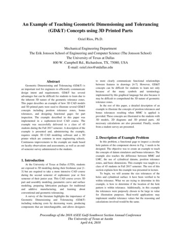
5C-2Design ManualChapter 5 - Roadway Design5C - Geometric Design CriteriaGeometric Design ElementsA. Level of ServiceLevel of service (LOS) is a measure of the operating conditions of a roadway facility. LOS is basedupon traffic performance related to speed, travel time, freedom to maneuver, traffic interruptions, andcomfort and convenience. The LOS ranges from A (least congested) to F (most congested). Refer tothe Highway Capacity Manual for a more thorough discussion of the LOS concept.Based upon the traffic capacity analysis, the number of lanes, turn lanes, and intersection controlsshould be selected to provide a design with the desired LOS for the design year traffic. Design yeartraffic is based upon a 20 year traffic projection. The current Highway Capacity Manual and thecurrent AASHTO “Green Book” should be used for traffic projections and to determine the numberof lanes and intersection configuration at the desired LOS.The LOS for the roadway overall is based upon Average Daily Traffic (ADT), while the LOS atsignalized intersections is based upon the peak hourly volume (PHV).As a planning tool, refer to the generalized service volume tables in FHWA’s Simplified HighwayCapacity Calculation Method for the Highway Performance Monitoring pubs/pl18003/hpms cap.pdf).The 2010 Highway Capacity Manual, issued in 2013, indicates there is no reduction in lane capacityuntil the lane width is less than 10 feet. For lanes less than 10 feet wide, the adjustment factor is 0.96.B. Sight DistanceThe following information is taken from the 2004 AASHTO “Green Book.” The Project Engineershould check the current edition of the AASHTO “Green Book” when specific information is neededto verify values provided.1. Stopping Sight Distances: The minimum stopping sight distance is the distance required by thedriver of a vehicle traveling at the design speed to bring the vehicle to a stop after an object on theroad becomes visible. This distance directly affects the length and rate of curvature for verticalcurves.The method for measuring stopping sight distance on vertical curves assumes a height for thedriver’s eye and a height for an object in the road. For a crest vertical curve, the sight distance isthe distance at which an object in the road appears to the driver over the crest of the curve.1Revised: 2021 Edition
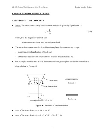
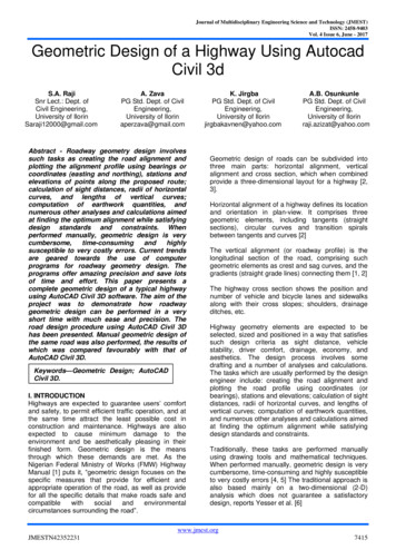
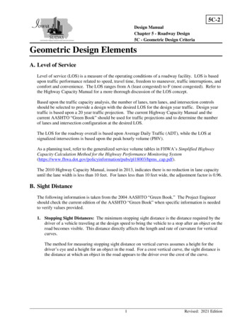
Chapter 5 - Roadway DesignSection 5C-2 - Geometric Design ElementsFigure 5C-2.01: Vertical Sight Distance DeterminationStopping sight distance is calculated based upon an assumed height of the driver’s eye and anassumed height of an object in the roadway. For all sight distance criteria, the height of thedriver’s eye is assumed to be 3.5 feet above the surface of the road, as recommended byAASHTO. Tables 5C-1.01 and 5C-1.02 in Section 5C-1 assume two different values for theheight of the object in the roadway. The “Acceptable” values in Table 5C-1.02 use a 2 footobject height according to the current edition of the AASHTO “Green Book.” The “Preferred”values in Table 5C-1.01 assume an object height of only 6 inches. This lower object height wasthe design value used in previous versions of the AASHTO “Green Book.” The results ofassuming a smaller object height for the preferred values in Table 5C-1.01 are higher required Kvalues and longer vertical curves.2. Sight Distance on Horizontal Curves: The horizontal alignment must provide at least theminimum stopping distance for the design speed at all points. This includes visibility aroundcurves and roadside encroachments.Where there are sight obstructions such as walls, cut slopes, buildings, fences, bridge structures,or other longitudinal barriers on the inside of curves, an adjustment in the minimum radius of thecurve may be necessary. In no case should sight distance be less than the stopping sight distancespecified in Tables 5C-1.01 and 5C-1.02 in Section 5C-1. The sight distance design procedureshould assume a 6 foot fence (as measured from finished grade) exists along all property linesexcept in the sight distance triangles required at all intersections.Available sight distance around a horizontal curve can be determined graphically using themethod shown in Figures 5C-2.02 and 5C-2.03 below. From the center of the inside lane (PointA), a line is projected through the point on the obstruction that is nearest to the curve (Point B).The line is then extended until it intersects the centerline of the inside lane (Point C).2Revised: 2021 Edition
Chapter 5 - Roadway DesignSection 5C-2 - Geometric Design ElementsFigure 5C-2.02 and Figure 5C-2.03: Sight Distances for Horizontal CurvesSource: Adapted from AASHTO “Green Book,” 2004 Edition, Exhibits 3-53 and 3-543Revised: 2021 Edition
Chapter 5 - Roadway DesignSection 5C-2 - Geometric Design Elements3. Passing Sight Distance: Passing sight distance is the minimum sight distance that must beavailable to enable the driver of one vehicle to pass another safely and comfortably withoutinterfering with oncoming traffic traveling at the design speed. Two lane roads should provideadequate passing zones at regular intervals. Minimum passing sight distances are shown inTables 5C-1.01 and 5C-1.02 in Section 5C-1.Passing sight distance is measured between an eye height of 3.5 feet and an object height of 3.5feet. On straight sections of roadway, passing sight distance is determined primarily by thevertical curvature of the roadway. On horizontal curves, obstructions adjacent to the roadway onthe inside of the curve can limit sight distance. This is most common in a cut section where theadjacent terrain projects above the surface of the roadway. Passing sight distance should beverified using the methods described in the current edition of the AASHTO “Green Book.”4. Intersection Sight Distance: In addition to the stopping sight distance provided continuously inthe direction of travel on all roadways, adequate sight distance at intersections must be providedto allow drivers to perceive the presence of potentially conflicting vehicles. Sight distance is alsorequired at intersections to allow drivers of stopped vehicles to decide when to enter or cross theintersecting roadway. If the available sight distance for an entering or crossing vehicle is at leastequal to the appropriate stopping sight distance for the major road, then drivers have sufficientsight distance to anticipate and avoid collisions. However, in some cases, this may require amajor road vehicle to slow or stop to accommodate the maneuver by a minor road vehicle. Toenhance traffic operations, intersection sight distances that exceed stopping sight distances aredesirable along the major road.Each intersection has the potential for several different types of vehicular conflicts. Thepossibility of these conflicts actually occurring can be greatly reduced by providing proper sightdistance and appropriate traffic controls. Each quadrant of an intersection should contain atriangular area free of obstructions that might block an approaching driver’s view of potentiallyconflicting vehicles. This clear area is known as the sight triangle.a. Sight Triangles: Proper sight distance at intersections is determined through theestablishment and enforcement of sight triangles. The required dimensions of the legs of thetriangle depend on the design speed of the roadways and the type of traffic control providedat the intersection. Two types of clear sight triangles are considered in intersection design:approach sight triangles and departure sight triangles.1) Approach Sight Triangles: Approach sight triangles allow the drivers at uncontrolledor yield controlled intersections to see a potentially conflicting vehicle in sufficient timeto slow or stop before colliding within the intersection. Although desirable at allintersections, approach sight triangles are not needed for intersections approachescontrolled by stop signs or traffic signals.2) Departure Sight Triangles: A second type of clear sight triangle provides sight distancesufficient for a stopped driver on a minor-road approach to depart from the intersectionand enter or cross the major road. Departure sight triangles should be provided in eachquadrant of each intersection approach controlled by a stop sign.At signalized intersections, the first vehicle stopped on one approach should be visible to thedriver of the first vehicle stopped on each of the other approaches. Left turning vehiclesshould have sufficient sight distance to select gaps in oncoming traffic.The recommended dimensions of the sight triangles vary with the type of traffic control usedat an intersection because different types of controls impose different legal constraints ondrivers and, therefore, result in different driver behavior. The AASHTO “Green Book”4Revised: 2021 Edition
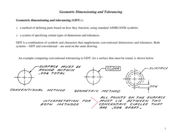
Chapter 5 - Roadway DesignSection 5C-2 - Geometric Design Elementscontains the required procedures, equations, and tables for determining the required sightdistance under various intersection and traffic control configurations.b. Identification of Sight Obstructions within Sight Triangles: Within a sight triangle, anyobject at a height above the elevation of the adjacent roadways that would obstruct thedriver’s view should be removed or lowered if practical. Such objects may include buildings,parked vehicles, highway structures, roadside hardware, hedges, trees, bushes, unmowedgrass, tall crops, walls, fences, and the terrain itself. Particular attention should be given tothe evaluation of clear sight triangles at intersection ramp/crossroad intersections wherefeatures such as bridge railings, piers, and abutments are potential sight obstructions.The determination of whether an object constitutes a sight obstruction should consider boththe horizontal and vertical alignment of both intersecting roadways, as well as the height andposition of the object. In making this determination, it should be assumed that the driver’seye is 3.5 feet above the roadway surface and that the approaching vehicle to be seen is 3.5feet above the surface of the intersecting road.C. Horizontal Alignment1. Roadway Curvature and Superelevation: On urban streets where operating speed is relativelylow and variable, the use of superelevation for horizontal curves can be minimized. Althoughsuperelevation is advantageous for traffic operation, in urban areas the combination of widepavements, the need to meet the grade of adjacent properties, the desire to maintain low speedoperation, the need to maintain pavement profiles for drainage, and the frequency of cross streetsand driveways and other urban features often combine to make the use of superelevationimpractical or undesirable. Generally, the absence of superelevation on low speed urban streets isnot detrimental to the motorist and superelevation is not typically provided on urban streets with adesign speed of 45 mph or less.The preferred radii shown in Section 5C-1, Table 5C-1.01 assume that a normal crown ismaintained around a horizontal curve. With a standard 2% pavement cross-slope, this effectivelyresults in a negative 2% superelevation for the outside lane. For roadways with a cross-slopeother than 2%, including four lane and wider sections that utilize a steeper cross-slope for theoutside lanes, the required curve radius should be determined from the guidance provided in thecurrent AASHTO “Green Book” or from Figure 5C-2.04 below.While superelevation on low speed urban roadways is not desirable, it may be necessary insituations where site conditions require a horizontal curve that cannot sustain traffic with thenegative superelevation that results from maintaining the normal crown. For these situations,superelevation equal to the normal cross-slope may be provided for the outside lane. Section 5C1, Table 5C-1.02 assumes the adverse crown in the outside lane of a curve is removed. For aroadway with a normal 2% cross-slope, this results in a superelevation of 2% across the width ofthe pavement. For roadways with cross-slopes other than 2%, the required radius and theresulting superelevation should be determined from the guidance provided in current AASHTO“Green Book” or from Figure 5C-2.04 below. The maximum superelevation for low speed urbanroadways should not exceed the normal cross-slope or a maximum of 3%.For roadways with design speeds of 50 mph or greater, superelevation of the roadway isacceptable and expected by motorists. The radii provided in Section 5C-1, Tables 5C-1.01 and5C-1.02 are based upon superelevation rates of 4% and 6% respectively. The maximumsuperelevation rate in urban areas should not exceed 6%.5Revised: 2021 Edition
Chapter 5 - Roadway DesignSection 5C-2 - Geometric Design ElementsFigure 5C-2.04: Superelevation, Radius, and Design Speed for Low Speed ( 50mph)Urban Street DesignSource: AASHTO “Green Book,” 2004 Edition, Exhibit 3-172. Intersection Alignment: The centerline of a street approaching another street from the oppositeside should not be offset. If the offset cannot be avoided, the offset should be 150 feet or greaterfor local streets. The centerline of a local street approaching an arterial or collector street fromopposite side should not be offset unless such offset is 300 feet or greater.3. Adding, Dropping, or Redirecting Lanes:a. Dropping or Redirecting Through Lanes: When dropping a lane, the minimum taper ratioto be used should be determined by the following formula, or from Table 5C-2.01:L WS for velocities of 45 mph or moreL WS2 for velocities of 40 mph or less.60L Minimum length of taper.S Numerical value of posted speed limit or 85th percentile speed, whichever is higher.W Width of pavement to be dropped or redirection offset.Preferably, taper ratios should be evenly divisible by five. Calculations that result in oddratios should be rounded to an even increment of five. The table below utilizes the formulasto determine the appropriate taper ratio for dropping a 12 foot wide lane. The ratio remainsconstant for a given design speed while the length varies with the pavement width.6Revised: 2021 Edition
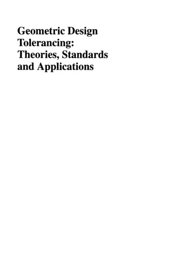
Chapter 5 - Roadway DesignSection 5C-2 - Geometric Design ElementsThe procedure for determining minimum taper ratios for redirecting through lanes is the sameas for lane drops, except for design speeds over 45 mph the use of reverse curves rather thantapers is recommended.Table 5C-2.01: Length and Taper Ratio for Dropping 12 Foot LaneDesign Speed (mph)Taper RatioLength (feet)253035404550556010:1 15:1 20:1 25:1 45:1 50:1 55:1 60:1120 180 240 300 540 600 660 720b. Adding Through or Turn Lanes: For design speeds of 45 mph or greater, a 15:1 lane tapershould be used when adding a left or right turn lane. For design speeds less than 45 mph, a10:1 taper may be used.For design speeds less than 45 mph, shorter tapers that are squared off or taper at 1:1 mayprovide better “targets” for approaching drivers and give more positive identification to anadded through lane or turn lane. For turn lanes, the total length of taper and decelerationlength should be the same as if a standard taper was used. This results in a longer length offull width pavement for the turn lane. This design provides increased storage that may reducethe likelihood turning vehicles will back up into the through lane during peak traffic periods.The use of short taper sections must be approved by the Engineer.Figure 5C-2.05: Adding or Dropping LanesFigure 5C-2.06: Redirecting Through Lanes7Revised: 2021 Edition
Chapter 5 - Roadway DesignSection 5C-2 - Geometric Design ElementsD. Vertical Alignment1. Minimum Grades: Flat and level grades on uncurbed pavements are preferred when thepavement is adequately crowned to drain the surface laterally. However, with curbed pavements,longitudinal grades must be provided to facilitate surface drainage. A typical minimum grade is0.5%, but a grade of 0.4% may be used in isolated areas where the pavement is accuratelycrowned and supported on firm subgrade. The minimum allowance grade for bubbles and cul-desacs is 1%. Particular attention should be given to the design of stormwater inlets and theirspacing to keep the spread of water on the traveled way within tolerable limits. Roadsidechannels and median swales frequently require grades steeper than the roadway profile foradequate drainage.2. Maximum Grades: Grades for urban streets should be as level as practical, consistent with thesurrounding terrain. The maximum design grades specified in Section 5C-1, Table 5C-1.02should be used infrequently; in most cases grades should be less than the maximum design grade.Where sidewalks are located adjacent to a roadway, a maximum roadway grade of 5% isdesirable. ADA requirements allow sidewalks adjacent to a roadway to match the running gradeof the roadway, regardless of the resulting grade. However, sidewalk accessibility is greatlyenhanced, especially over long distances, when grades are limited to 5% or less. It is recognizedthat meeting limitations will not be possible or practical in many situations; however, an attemptshould be made to limit roadway grades to this level, especially in areas with high levels ofanticipated pedestrian usage.3. Maximum Grade Changes: Except at intersections, the use of grade breaks, in lieu of verticalcurves, is not encouraged. However, if a grade break is necessary and the algebraic difference ingrade does not exceed 1%, the grade break will be considered by the Engineer.4. Vertical Curves: Vertical curves should be simple in application and should result in a designthat is safe, comfortable in operation, pleasing in appearance, and adequate for drainage.The major control for safe operation on crest vertical curves is the provision of ample sightdistances for the design speed. Minimum stopping sight distance should be provided in all cases.Wherever economically and physically feasible, more liberal stopping sight distances should beused. Furthermore additional sight distance should be provided at decision points.a. Crest Vertical Curves: Minimum lengths of crest vertical curves as determined by sightdistance requirements are generally satisfactory from the standpoint of safety, comfort, andappearance. Figure 5C-2.06 shows the required length of crest vertical curve to providestopping sight distance based upon design speed and change in grade.b. Sag Vertical Curves: Headlight sight distance is generally used as the criteria fordetermining the length of sag vertical curves. When a vehicle approaches a sag vertical curveat night, the portion of highway lighted ahead is dependent on the position of the headlightsand the direction of the light beam. A headlight height of 2 feet and a 1 degree upwarddivergence of the light beam from the longitudinal axis of the vehicle is commonly assumed.For safety purposes, the sag vertical curve should be long enough that the light beam distanceis the same as the stopping sight distance. Figure 5C-2.07 specifies the required sag curvelength to meet the sight distance assumptions made above.8Revised: 2021 Edition
Chapter 5 - Roadway DesignSection 5C-2 - Geometric Design ElementsFor both sag and crest vertical curves with a low algebraic difference in grade, sight distancerestrictions may not control the design of the curve. In these cases, rider comfort and curveappearance are the primary considerations for vertical curve design. Generally, vertical curveswith a minimum length (in feet) equal to three times the design speed (in mph) are acceptable.If a roadway has continuous lighting, the length of sag vertical curve (L) may be based onpassenger comfort instead of headlight sight distance. Use the following equation for the curvelength:𝐿 𝐴𝑉 246.5where A algebraic difference in grades, %V design speed, mph(Equation 3-51 AASHTO Greenbook, 2011)Drainage considerations also affect the design of vertical curves where curbs are utilized. Bothcrest and sag vertical curves that have a grade change from positive to negative (or vice versa)contain a level area at some point along the curve. Generally, as long as a grade of 0.30% isprovided within 50 feet of the level area, no drainage problems develop. This criterioncorresponds to a K value of 167 and is indicated by a dashed line in Figures 5C-2.06 and 5C-2.07below. K values greater than 167 may be utilized, but additional consideration should be given todrainage in these situations.K L(ft )(g 2 g1 )where g1 and g2 are in percentFigure 5C-2.06: Design Controls for Crest Vertical Curvesfor Stopping Sight Distance and Open Road ConditionsSource: “Green Book,” Exhibit 3-71, 20049Revised: 2021 Edition
Chapter 5 - Roadway DesignSection 5C-2 - Geometric Design ElementsFigure 5C-2.07: Design Controls for Sag Vertical Curves, Open Road ConditionsSource: “Green Book,” Exhibit 3-78, 20045. Intersection Grades: The grade of the "through" street should take precedence at intersections.At intersections of roadways with the same classifications, the more important roadway shouldhave this precedence. Side streets are to be warped to match through streets with as short atransition as possible, which provides a smooth ride. Consideration must be given to minimizesheet flow of stormwater across the intersection due to loss of crown on the side street.Carrying the crown of the side street into the through street is not allowed. In most cases thepavement cross-slope at the warped intersection should not exceed the grade of the through street.The maximum desirable grades of the through street at the intersection and the side street crossslope should be 2% and should not exceed 3%. The maximum desirable approach grade of theside street should not exceed 4% for a distance of 100 feet from the curb of the through street.Establishing intersection spot grades by matching “curb corners” of intersecting streets is notrecommended since it may result in an undesirable travel path from the through street to the sidestreet because of the resulting bump on the side street centerline. At sidewalk curb ramps inintersections, the street grades may need to be warped at the curb line to ensure the resultingcross-slope at the bottom of the ramp does not exceed 2%. A detail of the jointing layout withstaking elevations should be shown on the plans.ADA regulations set specific limits for crosswalk cross-slopes that directly impact street andintersection grades. ADA regulations limit the cross-slope to 2% (measured perpendicular to thedirection of pedestrian travel) for crosswalks that cross a roadway with stop control (stop sign) atthe intersection. For roadways without stop control (through movement or traffic signal) thecross-slope of the crosswalk is limited to 5%. Effectively, this requirement limits street grades toa maximum of 2% or 5% depending on intersection controls.For steep roadways without stop control, construction of a flattened “table” may be necessary toreduce the street grade to 5% or less at the location of the crosswalk. Crosswalk tables at these10Revised: 2021 Edition
Chapter 5 - Roadway DesignSection 5C-2 - Geometric Design Elementslocations must utilize vertical curves, appropriate for the design speed, to avoid a sudden changein grade at the intersection that could cause vehicles to bottom out or lose control.For steep roadways with stop control, construction of a flattened “table” may utilize grade breaksor shortened vertical curves to reduce the street grade to 2% or less at the location of thecrosswalk. A check should be made to verify that vehicles will not bottom out when travelingover the crosswalk table.E. Pavement CrownsThe following typical pavement crowns are straight line cross-slope and are desirable sections.1. Urban Roadways (Curb and Gutter): For streets with three or fewer travel lanes, the pavementcrown should be 2%.For streets with four or more travel lanes, the pavement crown for all inside lanes, including leftturn lanes, should be 2%. In order to reduce stormwater spread, the pavement crown for theoutside lanes should be 3%.For all streets, auxiliary right turn lanes will have varying pavement crowns depending on thedesired drainage pathway.2. Rural Roadways: For pavement crowns, a 2% cross-slope is normal with 4% shoulder slope.Iowa DOT Standard Road Plans should be checked for Federal Aid, Farm to Market, andSecondary Roads.F. Lane WidthThe lane width of a roadway greatly influences the safety and comfort of driving. Narrow lanes forcedrivers to operate their vehicles closer to each other laterally than they would normally desire,resulting in driver discomfort, lower operating speeds, and reduced roadway capacity.Tables 5C-1.01 and 5C-1.02 in Section 5C-1 indicate minimum lane widths based upon the roadwayclassification and adjacent land use. In addition to the lane width, a separate offset distance to thecurb is required. This curb offset is not included in the lane widths listed.Auxiliary lanes and turn lanes at intersections should be as wide as the adjacent through lanes. Thewidth for turn lanes is measured to the face of curb. Because motorists are slowing in anticipation ofmaking a turning movement, drivers are comfortable operating their vehicle closer to an adjacentobstacle (curb); therefore, turn lanes do not require a curb offset.G. Two-way Left-turn Lanes (TWLTL)Two-way left-turn lanes work well where design speeds are relatively low (25 to 50 mph) and thereare no heavy concentrations of left turning traffic. The width of TWLTLs should be limited to amaximum of 14 feet to discourage left-turning motorists from pulling out into the TWLTL andstopping perpendicular to the direction of traffic, while they wait for oncoming traffic to clear.11Revised: 2021 Edition
Chapter 5 - Roadway DesignSection 5C-2 - Geometric Design ElementsH. Raised Median WidthA median is defined as the portion of a roadway separating opposing directions of the traveled way.The median width is expressed as the dimension between the edges of the traveled way and includesthe left turn lanes, if any are present (refer to Section 5C-1, Figure 5C-1.01). The principal functionsof a median are to separate opposing traffic, allow space for speed changes and storage of left turningand U-turning vehicles, minimize headlight glare, and provide width for future lanes. For maximumefficiency, a median should be highly visible both night and day and contrast with the traveled waylanes.At unsignalized intersections on rural divided highways, the median should generally be as wide aspractical. However, in urban areas, narrower medians appear to operate better at unsignalizedintersections. If right-of-way is restricted, a wide median may not be justified if provided at theexpense of a narrowed border area. A reasonable border width is needed to adequately serve as abuffer between private development along the road and the traveled way. Narrowing the border areamay create operational issues similar to those that the median is designed to avoid. In addition, widemedians at signalized intersections result in increased time for vehicles to cross the median. This canlead to inefficient signal operation. Therefore, in urban areas, it is recommended that median widthbe only as wide as necessary to accommodate left turn lanes. Wider medians should only be usedwhere needed to accommodate turning and crossing maneuvers by larger vehicles.Medians and boulevards are not normally used on collector streets. However, when allowed, themedian or boulevard should conform to the same design standards as set forth for arterial streets.Median widths are also affected by sidewalk and crosswalk locations. Where a crosswalk cut throughis present or proposed, medians (exclusive of any turn lanes) must be a minimum of 6 feet wide tocomply with ADA regulations. These regulations require the placement of a 2 foot wide strip ofdetectable warnings at the curb line on both sides of the median. The detectable warnings must beseparated by a minimum 2 foot strip without detectable warnings. Where the median has no curb, thedetectable warnings must be placed along the edge of the roadway. At locations where a raisedmedian is stopped short of the crosswalk, the 6 foot raised median and associated detectable warningsare not required, and a standard 4 foot raised median section may be used.I. BridgesThe bridge widths listed in Section 5C-1, Tables 5C-1.01 and 5C-1.02 represent the clear roadwaywidth (width between barrier rail faces). The widths shown do not account for barrier rail widths,sidewalk, recreational trails, etc.For existing bridges, a structural analysis should be conducted. The existing bridge should be able toaccommodate legal loads. Bridge guardrail should be upgraded if necessary.J. Clear ZoneThe AASHTO Roadside Design Guide (RDG) defines the clear zone as “the total roadside borderarea, starting at the edge of the traveled way, available for safe use by errant vehicles. This area mayconsist of a shoulder, a recoverable slope, a non-recoverable slope, and/or a clear runout area. Thedesired width is dependent upon the traffic volumes and speeds and on the roadside geometry.”The intent of the clear zone is to provide an errant vehicle that leaves the roadway with anunobstructed recovery area. This area, including medians on divided roadways, should be kept freeof all unyielding objects, including utility and light poles, culverts, bridge piers, sign supports, and12Revised: 2021 Edition
Chapter 5 - Roadway DesignSection 5C-2 - Geometric Design Elementsany other fixed objects that might severely damage an out of control vehicle. Any obstruction thatcannot be placed outside of the clear zone should be shielded by traffic barriers or guardrails.According to the AASHTO RDG, the width of this area varies based upon traffic volumes, designspeed, and embankment slope.Embankment slopes can be classified as recoverable, non-recoverable, or critical. Embankmentslopes of 4:1 and flatter are consi
The following information is taken from the 2004 AASHTO "Green Book." The Project Engineer should check the current edition of the AASHTO "Green Book" when specific information is needed to verify values provided. 1. Stopping Sight Distances: The minimum stopping sight distance is the distance required by the