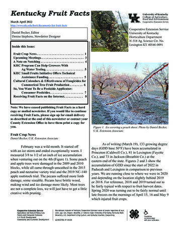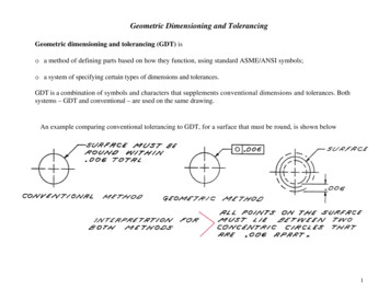
Transcription
Journal of Multidisciplinary Engineering Science and Technology (JMEST)ISSN: 2458-9403Vol. 4 Issue 6, June - 2017Geometric Design of a Highway Using AutocadCivil 3dS.A. RajiSnr Lect.: Dept. ofCivil Engineering,University of IlorinSaraji12000@gmail.comA. ZavaPG Std. Dept. of CivilEngineering,University of Ilorinaperzava@gmail.comAbstract - Roadway geometry design involvessuch tasks as creating the road alignment andplotting the alignment profile using bearings orcoordinates (easting and northing), stations andelevations of points along the proposed route;calculation of sight distances, radii of horizontalcurves, and lengths of vertical curves;computation of earthwork quantities, andnumerous other analyses and calculations aimedat finding the optimum alignment while satisfyingdesign standards and constraints. Whenperformed manually, geometric design is verycumbersome,time-consumingandhighlysusceptible to very costly errors. Current trendsare geared towards the use of computerprograms for roadway geometry design. Theprograms offer amazing precision and save lotsof time and effort. This paper presents acomplete geometric design of a typical highwayusing AutoCAD Civil 3D software. The aim of theproject was to demonstrate how roadwaygeometric design can be performed in a veryshort time with much ease and precision. Theroad design procedure using AutoCAD Civil 3Dhas been presented. Manual geometric design ofthe same road was also performed, the results ofwhich was compared favourably with that ofAutoCAD Civil 3D.Keywords—Geometric Design; AutoCADCivil 3D.I. INTRODUCTIONHighways are expected to guarantee users’ comfortand safety, to permit efficient traffic operation, and atthe same time attract the least possible cost inconstruction and maintenance. Highways are alsoexpected to cause minimum damage to theenvironment and be aesthetically pleasing in theirfinished form. Geometric design is the meansthrough which these demands are met. As theNigerian Federal Ministry of Works (FMW) HighwayManual [1] puts it, “geometric design focuses on thespecific measures that provide for efficient andappropriate operation of the road, as well as providefor all the specific details that make roads safe es surrounding the road”.K. JirgbaPG Std. Dept. of CivilEngineering,University of Ilorinjirgbakavnen@yahoo.comA.B. OsunkunlePG Std. Dept. of CivilEngineering,University of Ilorinraji.azizat@yahoo.comGeometric design of roads can be subdivided intothree main parts: horizontal alignment, verticalalignment and cross section, which when combinedprovide a three-dimensional layout for a highway [2,3].Horizontal alignment of a highway defines its locationand orientation in plan-view. It comprises threegeometric elements, including tangents (straightsections), circular curves and transition spiralsbetween tangents and curves [2]The vertical alignment (or roadway profile) is thelongitudinal section of the road, comprising suchgeometric elements as crest and sag curves, and thegradients (straight grade lines) connecting them [1, 2]The highway cross section shows the position andnumber of vehicle and bicycle lanes and sidewalksalong with their cross slopes; shoulders, drainageditches, etc.Highway geometry elements are expected to beselected, sized and positioned in a way that satisfiessuch design criteria as sight distance, vehiclestability, driver comfort, drainage, economy, andaesthetics. The design process involves somedrafting and a number of analyses and calculations.The tasks which are usually performed by the designengineer include: creating the road alignment andplotting the road profile using coordinates (orbearings), stations and elevations; calculation of sightdistances, radii of horizontal curves, and lengths ofvertical curves; computation of earthwork quantities,and numerous other analyses and calculations aimedat finding the optimum alignment while satisfyingdesign standards and constraints.Traditionally, these tasks are performed manuallyusing drawing tools and mathematical techniques.When performed manually, geometric design is verycumbersome, time-consuming and highly susceptibleto very costly errors [4, 5] The traditional approach isalso based mainly on a two-dimensional (2-D)analysis which does not guarantee a satisfactorydesign, reports Yesser et al. [6]www.jmest.orgJMESTN423522317415
Journal of Multidisciplinary Engineering Science and Technology (JMEST)ISSN: 2458-9403Vol. 4 Issue 6, June - 2017Current trends are geared towards the use of verysophisticated computer programs for roadwaygeometry design that offer amazing precision andsave lots of time and effort. Autodesk [7] summarizesthe importance of specialized road design softwaresaying the tools help civil engineering professionalsworking on transportation projects to: explorepreliminary design options and optimize projectperformance; determine optimal horizontal andvertical roadway geometry that are constrained bydesign criteria; engineer roadway geometry in thecontext of the existing environment more efficientlyand effectively. The tools also enable engineers towork with a more realistic model of what truly existsat the project site thereby affording engineers theopportunity to consider safety requirements earlier inproject development. As Ananya and Sahimol [4] putit, these computer applications can produce amazingvisual graphics that enable the design engineer toview the road on screen from the perspective of thedriver. They [4] further state that “without the use ofthree-dimensional modeling, highway planningexperiences a significant difficulty. Cut and fillcalculation tends to consume a significant amount oftime By using the object-oriented approach, theprocess of cut and fill calculation can be performedautomatically and in an accurate manner”.There are ongoing efforts to complete thedevelopment of campus road network of theUniversity of Ilorin, located in southwestern Nigeriantown of Ilorin. One of the links in the road networkthat has been selected for development is the oneleading to students’ hostels from the University busstop. This paper presents a complete geometricdesign of this road using AutoCAD Civil 3D software.The aim is to demonstrate how roadway geometricdesign can be performed in a very short time withmuch ease and precision so as to encourage civilengineering practitioners in the developing world toembrace the use of road design software. To providea basis for comparison, manual design of thegeometry of the same road was also performed.II. AUTODESK AUTOCAD CIVIL 3DAutoCAD Civil 3D is a civil engineering design anddocumentation tool developed by Autodesk.AutoCAD Civil 3D software supports BuildingInformation Modeling (that is, digital representation ofthe physical and functional characteristics of afacility). It is used for modeling, analysis and designof a variety of civil infrastructure project types,including roads and highways, land development,rail, airports, and water. AutoCAD Civil 3D helps civilinfrastructure professionals improve project delivery,maintain more consistent data and processes, andrespond faster to project changes, all within thefamiliar AutoCAD environment [8]Autodesk [7] lists the features of AutoCAD Civil 3Das follows:i.ii.iii.iv.v.BIM tools for civil engineering design:AutoCAD Civil 3D supports BuildingInformation Modeling (BIM) and helps reducethe time it takes to design, analyze, andimplement changes.Efficient civil design: AutoCAD Civil 3Dperforms faster design iterations with anintelligent, 3D model-based application thatdynamically updates related civil designelements when changes are made.Itstreamlines time-consuming tasks forcorridor design, parcel design, and pressureand gravity network design.It improves civil drafting and documentation.Connecting design and documentation helpsboost productivity and deliver higher-qualitydesigns and construction documentation.Changes to design elements are captured indocumentation, minimizing manual updates.GPS surveying tools for faster processing.GPS surveying and data collection tools inAutoCAD Civil 3D can help you update yourprocesses for improved project delivery.Integrated storm water management andgeospatial analysis. AutoCAD Civil 3D helpsthe designer to improve project delivery andmake more informed decisions usingvisualization, simulation, and water analysisintegrated with the design process for stormwater management, geospatial analysis, andmodel analysis.III. DESIGN METHODOLOGYA. Survey Data CollectionThe existing ground surface data are required fordesigning the geometry of highways. The surveyinformation of the proposed route was obtained fromthe firm handling the development of the road. Thesurvey information included Easting, Northing andelevations of points along the proposed route.B. Design CriteriaThe following design criteria based on the NigerianFederal Ministry of Works Manual [1] were assignedto the horizontal geometry of the center line and alsoto the profile and cross section of the roadway:i.Design speed 60 km/hii.Superelevation rate 4%iii.Friction factor 0.14iv.Minimum Stopping Sight Distance 130 mv.Minimum Passing Sight Distance 540 mvi.Maximum grade 7%vii.Minimum K (rate of vertical curvature) for sagcurves 30viii.Minimum K (rate of vertical curvature) forcrest curves 26.ix.Roadway width 12.8 mx.Carriageway width 7.3 mxi.Shoulder width 2.75 mC. rgJMESTN423522317416
Journal of Multidisciplinary Engineering Science and Technology (JMEST)ISSN: 2458-9403Vol. 4 Issue 6, June - 2017 Import survey data (comprising easting,northing and levels and saved in Note Padformat) into the AutoCAD Civil 3Denvironment.Create existing ground surfaceCreate alignment by linking points on theexisting ground using polylineApply the design criteria. In this project, theAASHTO design criteria was selected.Generate the existing ground profile.Create the formation level (finished) usingthe profile creation tools.Create the Assembly, which defines thecross-sectional component of the design.The assembly is constructed by connectingindividual subassembly objects.Create the corridor, which is the resultingdynamic 3D model representation built fromthe combination of horizontal, vertical andcross-sectional design elements. Corridorsmay be used to calculate earthworks andquantitytakeoffs,toperformsight and visual analysis, to generatesurfaces, and to extract information forconstruction purposes.Generate volume table report.D. Design of the Horizontal AlignmentHorizontal alignment design entails determining theminimum curve radius and curve length, and thecomputation of horizontal offsets from tangents to thecurve to facilitate locating the curve in the field. Thissection presents an overview of the horizontalalignment design procedure by means of AutoCADCivil 3D and by manual method.The survey data comprising easting, northing andelevations was imported into the Civil 3Denvironment in notepad format. This automaticallygenerated the existing ground surface. Afterspecifying the design criteria that were to be placedon the alignment, the polyline construction tool fromthe toolbar was used to draw the layout of the road.The ‘Geometry Editor’ tool was used to draw thecircular and spiral curves and to extract the alignmentcurve report.On the other hand, the easting and northing of theroadway center line was extracted from the surveydata and plotted using Microsoft Excel with theeasting as the abscissa and the northing as theordinate. This plot produced the horizontal alignmentof the proposed route. Using the design speed,superelevation rate and the friction factor specified inthe design criteria, the minimum curve radius wascalculated from the formula in equation 1𝑅 V design speed in km/he superelevation rate.µ friction factor.E. Design of the Vertical AlignmentThe existing ground profile was generated using the‘Profile’ tool from the toolbar, while the finishedgrades were created graphically using the profilecreation tools. Profile geometry was determined byapplying the design criteria of minimum K values forsag and crest vertical curves that satisfy theminimum requirements of stopping sight distance,comfort and appearance criteria.Lengths of vertical curves were also calculatedmanually using the formula𝐿 𝐾𝐴(2)Where L minimum length of vertical curve inmeters.K the rate of vertical curvature, defined as thelength of curve per percent algebraic difference inintersecting grades.A algebraic difference of grades in percent.F. Cut and Fill Calculation.A feature within AutoCAD Civil 3D allows for thecalculation of earthwork required on a project within afew seconds. After creating the ground surface andthe proposed finished grade surface, AutoCAD Civil3D makes it easy to create a comparison surfacewhich highlights the elevation difference andcomputes the volume between the two surfaces. Theprocess of calculating earthwork begins by clicking‘Surfaces’ on the Modify tab. A volume report sheetcan then be printed.IV. DESIGN OUTPUTThis section presents the geometric design outputfrom AutoCAD Civil 3D and from manual design.A. Horizontal AlignmentThe existing ground profile and the horizontalalignment produced by AutoCAD Civil 3D arepresented in Figures 1 and 2 respectively. Also thehorizontal alignment determined manually ispresented in Figure 3. Comparison of Fig. 2 and 3shows that the horizontal alignments produced bymeans of AutoCAD Civil 3D and manual design aresimilar.𝑉2127(𝑒 𝜇)(1)Where R minimum horizontal curve radius inmeterswww.jmest.orgJMESTN423522317417
Journal of Multidisciplinary Engineering Science and Technology (JMEST)ISSN: 2458-9403Vol. 4 Issue 6, June - 2017Fig. 1: Existing Ground Surface produced byAutoCAD Civil 3D.Fig. 2: Horizontal Alignment produced by AutoCADCivil 3DFig. 3: Horizontal Alignment produced from the plot of Easting and Northing using ExcelB. Vertical Alignment Design Output.The vertical alignment design outputs by bothAutoCAD Civil 3D and manual designs are presentedin Fig. 4 and 5 respectively. It is evident from thesetwo figures that the profiles obtained by means ofAuoCAD Civil 3D and manual methods are similar.www.jmest.orgJMESTN423522317418
Journal of Multidisciplinary Engineering Science and Technology (JMEST)ISSN: 2458-9403Vol. 4 Issue 6, June - 2017Fig. 4: Vertical alignment produced by AutoCAD Civil 3DFig. 5: Vertical alignment produced by manual designC. Cut and Fill ReportTable 1 represents part of the volume report for this design.Figure 1: Earth Volume Reportwww.jmest.orgJMESTN423522317419
Journal of Multidisciplinary Engineering Science and Technology (JMEST)ISSN: 2458-9403Vol. 4 Issue 6, June - 2017D. AssembliesAssemblies define the cross-sectional component ofthe design. They are built by connecting individualsubassembly objects, thereby helping to simulate thegeometry and material make up of the road. Fig. 6shows the roadway assembly.Fig. 6: Roadway Assembly.V. CONCLUSIONwww.jmest.orgJMESTN423522317420
Journal of Multidisciplinary Engineering Science and Technology (JMEST)ISSN: 2458-9403Vol. 4 Issue 6, June - 2017The use of AutoCAD Civil 3D for highway geometricdesign makes the design process to be completedwithin a very short time and with much ease andamazing precision. These capabilities of AutoCADCivil 3D eliminate the major disadvantages of themanual design approach that is cumbersome, timeconsuming and highly prone to costly errors.[6]H. Yasser, M.E. Said, and A.O. Abd ElHalim, “State-of-the-Art of ThreeDimensional Highway Geometric Design”,Canadian Journal of Civil Engineering, Vol.25, No. 3, pp. 500-511, 1998. Available 39/l97-111.[7]Autodesk, “Highway Engineering and RoadDesign Software – InfraWorks”, list-view. Accessed February 2107[8]Autodesk, “Civil EngineeringDesign/AutoCAD Civil 3D”, Available -3d/features/all. Accessed February2107.[9]Excitech Ltd., ” AutoCAD Civil 3D 2017”,Available vil-3D-2017. Accessed February 2107.REFERENCES[1]Federal Ministry of Works Highway Manual,“Geometric Design”, Nigeria. Part 1, Vol. 1, 2013.[2]E.T. Demetrios, “Highway Engineering”, TheMcGraw-Hill Companies, Inc. New York, USA, 1999.[3]Wikipedia “Geometric Design of Roads”.Available from:https://en.wikipedia.org/wiki/Geometric design of roads. Accessed February 2107.[4]A. Ananya, and E. Sahimol, “3D Model forHighway Alignment”, International Journal ofScientific Engineering and Research(IJSER), Volume 4, Issue 3, March 2016.[5]L. Chen-Fu and D.M. Levinson, “ROAD:Interactive Geometric Design Tool forTransportation Education and Training”,Journal of Professional Issues in EngineeringEducation & Practice, Vol. 139, No. 2, pp 116– 122, April 2013.www.jmest.orgJMESTN423522317421
using AutoCAD Civil 3D software. The aim of the project was to demonstrate how roadway geometric design can be performed in a very short time with much ease and precision. The road design procedure using AutoCAD Civil 3D has been presented. Manual geometric design of the same road was also performed, the results of