Transcription
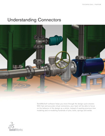
T E C H N I C A LP A P E RUnderstanding ConnectorsSolidWorks software helps you move through the design cycle smarter.With fast and accurate virtual connectors, your team will be able to focuson the behavior of the design as a whole, instead of wasting precious timemodeling and re-modeling hundreds of pins, bolts, springs and welds.
IntroductionConnectors may be one of the most frequently overlooked aspects of design engineering. Though we usecountless products every day that incorporate them, connectors rarely receive a lot of attention. But if you everstop to think about how many things have pins, bolts, springs, welds, and other pieces of hardware, you’ll soon seehow vital connectors are. They quite literally hold everything together.Trying to understand how a design works without studying its connectors is like trying to read an essay without itsconjunctions. “And” versus “but” makes a major difference – so does a pin versus a bolt. In the past, you couldspend days modeling the connections for an assembly, analysis, only to find that a modification in the design meantgoing right back to square one and starting all over again.But what if you didn’t have to? What if the software were smart enough to do the tedious parts for you?SolidWorks Simulation is. SolidWorks has made working with connectors quick and easy, replacing the geometry ofthe “real” hardware with idealized virtual connectors. These simulated connectors impose the behavior of their “real”counterparts on the rest of the design without requiring the painstaking analysis of each pin or bolt. SolidWorksSimulation takes no shortcuts in accuracy with its virtual connectors, but, by putting many of the tasks formerlyperformed by analysts into the software, it speeds up the simulation process, leaving you more time to do whatyou do best: designing.This paper describes the different types of virtual connectors provided in SolidWorks Simulation and discusseshow they are modeled in Finite Element Analysis (FEA) in SolidWorks. By understanding how the connectors areconstructed one can better judge when and where to use them.Background InformationIn order to understand how connectors work, it is worth recapping a fundamental part of FEA theory. When solvinga structural problem the system breaks the model down into many discrete elements, which are then solved. Thereare many classes of elements that can be used, but SolidWorks Simulation connectors only use a small subset. Beam elements: in which a line representation of the model is meshed and solved; the user defines thebeam’s cross sectional values and the solution is then calculated Rigid elements: a special beam element of infinite stiffness Spring elements: a special beam element of finite stiffness, in which the user specifies individualstiffness valuesSolidWorks Simulation uses a mixture of beam, rigid and spring elements to mimic the behavior of the “real”connector in its simulation virtual counterpart.SolidWorks Simulation connectors can be classified into two groups: “hardware replacement connectors” and“specialized simulation connectors.” The first category includes connectors that model everyday objects like pins,bolts, and welds. The second comprises more theoretical connectors that have more idealized applications.1
Hardware Replacement ConnectorsSpringsA spring connector, modeled using a spring element, offers you the opportunity to see spring behavior in simulationwithout detailing specific spring geometry and parameters. Modeling a spring in the traditional way with FEA is verycomplicated. The spring’s stiffness has to be divided by the number of nodes on each face connected by the spring, butintricate adjustments are required if the numbers of nodes on each face vary. Furthermore, uneven mesh distributioncan intrinsically alter stiffness values. Fortunately, SolidWorks software can quickly evaluate the proper stiffness of aspring connector based on the mesh distribution.Spring connectors can join flat parallel faces, concentric cylindrical faces or two point locations (vertices). For the twoface-defined spring connectors, the springs appear only on the common areas of projection to prevent unintendedmoments from forming, as shown in Figure 1 below.FIGURE 1. HOW SPRINGS ARE PLACED BETWEEN COMPONENTS WITH THESE FACES APPEAR THE SAME,NOT DIFFERENT.There are three types of spring connectors: tension-only, compression-only, and tension-compression. Tension-onlysprings are useful for modeling cables and strings, whereas compression-only springs are intended for bumpers.Tension-compression spring connectors are a catch-all that model regular springs effectively. In addition to location andspring type, the spring connector requires two further parameters to be defined: stiffness and any pre-load.Stiffness can be defined as either a total (i.e. a total force per unit length) or distributed (i.e. “stiffness density”, or a pressure per unit length) value. A total stiffness value is useful for parallel faces, while a distributed setting is more valuablewhen the connecting faces have different shapes and sizes. In this case, you may have to run several iterations basedon area calculations to make sure that the overall desired stiffness is achieved.Finally, another stiffness parameter known as “pre-load” can be defined. If a spring is compressed (e.g. a push-downballpoint pen) or extended in standard operation, its strength and stiffness changes. SolidWorks Simulation allows youto define those pre-load conditions so the software can quickly evaluate how the spring’s behavior changes.2
Elastic SupportsThe elastic support is a type of fixture which acts much like a spring connector: it resists tension and compressionbetween two surfaces. The main difference is that spring connectors connect two parts or assemblies together whereasthe elastic support connects a face of the part or assembly to the virtual ground. In other words, the elastic supportattaches a flexible part or assembly to an infinitely stiff location. A simple example of an actuator with an elastic supportconnector is shown in Figure 2 below.FIGURE 2. AN ACTUATOR WITH AN ELASTIC SUPPORT (INDICATED BY THE SMALL RED CONES).The elastic support is created using tension-compression spring elements and defined by setting two parameters, thenormal and shear stiffnesses. As with the spring connector the stiffness can be expressed as a distributed or total value.The elastic support fixture saves significant time compared with hand calculations when studying a device with flexiblesupports.3
Spring-DampersSpring-damper connectors are, in fact, spring elements, but they differ in a few ways from the more common springconnectors. First and foremost, as the hyphenated word implies, damping conditions can be defined. This dampingcoefficient opposes the velocity of a device moving in simulation, just as one would expect with a drag force. There isanother parameter, too: rotational stiffness. In studies with spring-dampers, rotation is also accounted for, instead ofsimply dealing with extension and compression.Surface connections are another major difference. Although spring connectors join overlapping projections of faces,spring-damper connectors join individual vertices. This is somewhat like the link versus the rigid connector(see page 13).Finally, and perhaps most importantly, spring dampers can only be used in linear dynamic (modal time history) studies.Springs are very versatile and can be implemented in a wide variety of studies, but the role of damping is most usefulin linear dynamics. A section view of a steering assembly with spring-damper connectors is shown in Figure 3 below.FIGURE 3. SECTION VIEW OF A PISTON WITH A SPRING-DAMPER CONNECTOR (INDICATED IN BLUE).In suspension or vibration isolation systems, the spring damper behavior has a dominate impact on the performance ofthe assembly. For dynamic problems, spring dampers must therefore be incorporated into the simulation.4
BearingsA bearing connector is a combination of spring elements that joins two concentric cylindrical parts and mimics thebehavior of a real-life bearing, allowing for translation and/or rotation between the two parts. Bearings are essentialcomponents of many designs because they allow smooth motion while reducing friction as compared with otherconnectors.1 SolidWorks provides you with virtual ball bearing and roller bearing connectors that replace manuallygenerated models of these parts but create the same effects on the rest of the system. A gearbox, shown in Figure 4below, contains an example of a bearing connector, shown in blue in the close-up on the right.FIGURE 4. THE GEARBOX BEARINGS (PINK) CAN BE REPLACED BY BEARING CONNECTORS (BLUE) TOACCELERATE THE SIMULATION SOLUTION.Bearing connectors can be defined as “rigid,” or “flexible” with their radial and axial stiffness values defined. Rigidbearing connectors prevent some motion, while flexible bearing connectors allow for limited local flexibility. Figure 5more explicitly demonstrates how the bearing connector behavior is modeled.1General types of bearings and how they work. Retrieved August 5, 2009, from ThomasNet Web site: supplies/bearing-types5
FIGURE 5. ACTUAL BEARING BEHAVIOR (RED) COMPARED WITH THREE LINEAR MODELS THAT CAN BE DEFINED INSOLIDWORKS.Figure 5 above shows how typical bearing behavior compares with three possible models. A ball bearing or rollerbearing normally provides little resistance to rotation up until some specified angle. At that point, the resistance torotation increases dramatically. Figure 5 shows this in red, where the stiffness slope K1 is much less than K2. It isclear why bearings are actually like spring elements: this behavior is much like a spring with two linear regions ofspring constants.The first model, shown in green, is non-conservative: it assumes no rotation is possible and provides infinite resistance.This corresponds to the “rigid” condition that is available for bearing rotation. On the opposite side of the spectrum,the blue line (K 0) acts like a frictionless ball joint. This model is fairly accurate for small angular displacementsbecause K1 is small, but it is inaccurate for large values. When you define stiffness values, SolidWorks Simulationsplits the difference between these approaches and produces a model like the gray line. Though none of these models are particularly accurate, the gray line approach does the best job of accommodating both of the stiffness values.The bearing fixture is related to the bearing connector, the difference being that the part or assembly to be analyzed isconnected to the virtual ground. So a bearing fixture attaches a flexible part or assembly to an infinitely stiff location.The major benefit of using the bearing connector instead of modeling a bearing within SolidWorks Simulation is theamount of time saved. Engineers and designers are interested in bearings mostly for the behavior that they induce inthe rest of the system. In other words, if bearings are placed between the handles and the handle rods of the crankshaft, what can someone do with it? Bearings are often assumed to be strong enough if made with the proper material, so modeling a connector avoids unnecessarily analyzing the stresses on the bearing.6
BoltsA bolt connector models a device that connects two components, multiple components, or a component and theground. It fixes these parts together – one piece can’t move or rotate with respect to the rest of the assembly. Ofcourse, bolts are vital fixtures in many mechanical designs. Consider the pipe route below: many bolts are used tobolt each section together.FIGURE 6. A PIPE ROUTE CONTAINS MANY BOLTED FLANGES, MODELED WITH BOLT CONNECTORS SHOWN INBLUE (RIGHT).Bolts can be difficult to simulate because of bolt pre-tension and shear, two factors that do not affect other connectors. But SolidWorks Simulation simplifies the analysis by replacing the bolt with a bolt connector made up ofa beam and rigid bars instead of a complete, intricate part. A tension-only beam (i.e. it resists tension but not compression) is used for the bolt’s shank, which allows pre-loading to be modeled as an axial force on the beam. If theshank tightly fits with the holes (i.e. they have the same diameter), the software connects bar elements betweenthe shank and the hole to model the shear effect. Because of those rigid bars that connect the beam with flangefaces, stresses close to the area of the bolt/nut may not be accurate. However, errors significantly decrease ashort distance (approximately 1 bolt diameter) from the bolt. SolidWorks Simulation also calculates axial and shearreactions at the bolt to determine bolt sizing, or whether the clamping force generated by the bolt size and thetightening torque is sufficient to overcome the external loads.SolidWorks Simulation is designed with built-in analysis intelligence, so that you need only define a few requiredparameters, and then let the program perform the difficult calculations. It allows you to pick one of five differentgeneric types of bolts, shown in Figure 7 below (L to R, top to bottom): counterbore with nut, countersink with nut,counterbore screw, countersink screw, and foundation bolt.7
FIGURE 7. THE FIVE BOLTS AVAILABLE IN SOLIDWORKS SIMULATION SOFTWARE.SolidWorks Simulation can also simulate the behavior of a foundation bolt (or grounded bolt) that attaches a part toa virtual ground (which is infinitely stiff). These are used in situations like road sign or traffic light posts, where thebolts are embedded in the concrete pavement. In this case, SolidWorks Simulation uses a virtual wall option to simulate the presence of a concrete floor, simplifying the analysis model size.After defining what type of bolt is to be created, the shank diameter, head diameter, material and pre-load conditionsare required. The bolt strength data – including pitch, bolt strength, and factor of safety – can be set for the increation of results plots.All these inputs can be defined in a single dialog. After reaching the solution, SolidWorks Simulation provides theresultant axial force, shear force and bending moments acting on the bolt. A check plot shows bolt connectors thatare below (passed) or above (failed) the defined bolt strength, allowing for rapid review of the possible failure of thebolt connectors.Virtual bolt connectors don’t provide data about the stress distribution on the bolt/nut, but rather the effect of thebolt on the parts adjacent to it, or on the overall assembly. If the stress distribution on the bolt/nut is important, youcan model bolt behavior by including the solid model of the bolt and nuts and then using contact conditions ratherthan the virtual bolt connector.As with other connectors, saving time is the primary benefit of using bolt connectors in SolidWorks Simulation.Specifically designing and defining these bolt parameters would take even an expert engineer a significant amountof time. Though full-scale modeling of a bolt may improve accuracy very near the bolt itself, through this approach,the effects on the general structure and the bolt’s behavior can be predicted quickly and fairly accurately with only afew inputs.PinsA pin connector is a solid beam element that allows rotation and/or translation between bodies. Think of puttinga bead on a straw: it is easy to spin the bead around the straw, and it can move up and down the straw, but it can’tturn easily in another direction. Alternatively, if the straw is very short, the bead might only be able to spin around itwithout translating. These simple examples aside, pins are crucial elements in many mechanical designs. Case inpoint: a pair of pliers modeled in SolidWorks (see Figure 8 below).8
FIGURE 8. A PAIR OF PLIERS MODELED IN SOLIDWORKS. A PIN CONNECTOR IS SHOWN (IN RED) TOWARDTHE CENTER.In conventional FEA, the analyst typically simulates the pin behavior by modeling the pin part in a finite elementmesh and then defining contact between the pin and the cylindrical faces of the pliers’ hands. In a SolidWorks simulation study, a pin connector is used (Figure 8) to join the two arms of the pliers about one axis. You simply selectthe cylindrical face of the hole in each arm in the pliers. SolidWorks Simulation allows you to define strength andconnection characteristics. You also need to select the desired movement - the pin connector can simulate pins thatrotate, slide back and forth, or both rotate and slide. Obviously, in the case of a set of pliers, the faces are free torotate against the pin but not slide. When complete, the red marks denote where the pin connection is placed.Despite the easy-to-use interface, the software performs the same complex tasks needed to define the FEA simulation of the pin described for traditional analysis. SolidWorks models the pin with a beam element, and connects it tothe cylindrical faces of the two parts with bar elements for which you have specified axial and rotational stiffness.The relative axial movement of the faces depends on the axial force that develops in the joint and the specified axialstiffness. Similarly, the relative rotation depends on the moment that develops in the joint and the specified rotationalstiffness. If you want to model a pure pin connection with free rotation, you can choose the option of “no translation,” and SolidWorks Simulation will automatically define axial stiffness so that there is no translation while allowingfree rotation.Designers and engineers usually want to know the effect of the pin on the parts adjacent to it or on the overallassembly, rather than the stress distribution on the pin itself. The virtual pin connector in SolidWorks Simulation wasdesigned for just such scenarios, and makes analysis faster and easier. With this capability, you can learn the forcesand moments acting on the pin, and use the information to determine the size of the pin.9
Another advantage of pin connectors in SolidWorks Simulation is repeatability. While an expert designer doinghand calculations may once have done separate models for each pin, SolidWorks designers can place multiple pinsand need only define some simple features such as tensile strength and connection limitations. In doing this, youcan save many hours and improve productivity.Spot WeldsSpot welds can be used to join two very thin pieces of metal – they function best when the parts are less than3 mm thick. A SolidWorks spot weld connector is modeled as a beam element that is shear-flexible. The tworequired parameters are the user-defined weld diameter and the distance between the parts being welded.Ultimately, this model mimics the functionality of spot welds in real life. After all, spot welds are formed by meltingmetal pieces together without any “filler.” 2 The same effect is true here: There is no filler. Spot weld connectors ina model car are shown below in Figure 9 in blue.FIGURE 9. SPOT WELDS (IN BLUE) JOIN THE ROOF TO THE SIDES OF A MODEL CAR.Creating spot welds is easy in SolidWorks Simulation. You simply define the two contact faces, the weld locations,and the diameters of the welds. A “no penetration” contact condition should be used to ensure proper systembehavior. The surfaces should not slip past each other, for example. With those contact conditions defined, the program computes stresses based on the forces applied, but you must be particularly careful with meshing. A coarsemesh may cause the program to join the spot weld and the nearest vertex in the mesh together. This may leadto unreasonable results. You should first run a coarse mesh and then add split lines to mesh the red areas – the“warning areas” – at a finer level. This will save computation time and be more accurate than taking the coarsemesh at face value.2Srikunwong, C., Dupuy, T. , & Bienvenu, Y. Numerical simulation of resistance spot welding process using FEA technique.10
In hand calculations, it is important for the engineer to know the material’s thickness and melting point, among otherproperties. Calculating the strength of the weld according to its size is another large undertaking. SolidWorkskeeps all the material data within its databases. The software alerts you when there is a problem with the proposedweld and provides a detailed description of the stresses and strains around the weld, provided proper mesh refinement is implemented.Edge WeldsEdge Weld connectors simulate how a weld would behave if applied between a face and an edge or between twoedges. The software accomplishes this through bonded contacts: all the nodes within the projection of ace set1 onto face set 2 are bonded together. Edge welds are very common features in engineering designs, like in thebrace shown in Figure 10 below.FIGURE 10. EDGE WELDS (DARK BLUE) JOIN PARTS OF A BRACE TOGETHER.You can select among four types of welds and then chooses the faces and intersecting edges where the programshould apply the weld. A weld material must also be defined, and an estimated weld size can be added to makethe program run fairly quickly. If weld size cannot be estimated, the program will require more time to run furtheriterations to provide a proper weld size estimate.11 11
FEA software utilizes the throat shear method to evaluate edge welds. Rather than rely solely on stresses – whichcan be unreliable and difficult to obtain near welds in any FEA software – the program computes normal, bending,and shear forces when estimating the welds as lines. Then, SolidWorks can determine an appropriate weld size forthe forces attained in accordance with industry standards. In SolidWorks Simulation, the edge weld sizes followthe guidelines set forth by the American Welding Society Section D1.1. 3 Other standards are currently beinginvestigated.SolidWorks Simulation can provide you with data that compares the minimum required weld size and the currentweld size at all points on the seam. An example is shown in Figure 11 below based on a static study of a weld onthe aforementioned brace.FIGURE 11. A SAMPLE PLOT COMPARING REQUIRED WELD SIZE (BLUE) AND THE CURRENT WELD SIZE (RED).Based on these results, you should take care that the weld is at least as thick as the largest required thickness.This will ensure that the entire weld is structurally sound.3(2006).Structural Welding Code-Steel. American Welding Society, (D1.1)11 22
Specialized Simulation ConnectorsRigidThe rigid connector is a simple concept, but it should only be applied if you are certain this is what you want. Thisconnector does exactly what it sounds like: it makes two faces rigid with respect to one another. SolidWorksplaces rigid bar connectors in between the selected surfaces. Figure 12 shows how these connectors function.FIGURE 12. A RIGID CONNECTOR (TOP, RED) KEEPS THE TWO MIDDLE SURFACES FIXED WITH RESPECT TO ONEANOTHER EVEN AFTER SIGNIFICANT LOADING (BOTTOM).11 33
Here, the square on the right is fixed while pressure (purple) is applied to the left square. Note that these surfacesneither translate nor rotate with respect to one another – the rest of the square deform, but these two faces do not.This is more extreme than the bonded contact simulation setting which still allows for some localized bending. Thestiffness here is infinite. You should be aware when applying this idealized setting that infinite stiffness can significantly affect the results in the rest of the system and may inappropriately model some real life cases. Be careful!LinksA link connector acts much like a rigid connector except it joins points instead of faces. A link is infinitely stiff: iftwo points are connected through a link, the distance between them will not change. A link connecting solid bodies at two points produces a rigid joint. If it connects shell bodies, it allows for rotation – more like a hinge. In eithercase, the distance between the two points does not change. The pictures in Figure 13 below show one example.FIGURE 13. TWO RODS CONNECTED VIA A LINK, BEFORE TESTING (LEFT) AND AFTER TESTING (RIGHT). A LINKJOINS THE TWO END VERTICES NO CIRCLE. THESE POINTS MAINTAIN THE SAME DISTANCE APARTIN TESTING.Here, a link joins the two top corners in between the bars. The right bar and the base of the left bar are fixed (left,in green). A small force (left, purple) is exerted on one edge. The picture on the right demonstrates how the linkworks within the no circle region: the two linked corners remain equidistant before and after the load is applied. Theunlinked area on the bottom (colored yellow and red) moves more, as expected – after all, the link does allow rotation of other points on the bodies.The major caveat with the link connector is that it can only be used for small displacements. SolidWorks Simulationmay not solve correctly if displacements are too large. Moreover, it is important for you to recognize that the link,like the rigid connector, is highly idealized. It can cause unpredictably high stresses if implemented improperly, soexercise caution and use it sparingly.14
ConclusionConnectors are some of the most important parts of many engineering designs. Countless devices incorporatepins, bolts, springs, welds, and all the other types of connectors. In the past, each connector would take significant,intensive time and effort for even the most experienced analysts – and if some parameters were changed, youwould have to begin your analysis anew. Imagine a large crane with hundreds or thousands of pins and bolts. Thestresses on each of those pins and each of those bolts may not be very important: You may care far more aboutthe stresses on the crane’s arm, to ensure that it can hold the proper weight without breaking. Why waste computation time and resources with a full model when you can use connectors?The connectors that make up SolidWorks Simulation allow for faster computation and faster adjustments than traditional FEA and hand calculations, and each connector only requires a few select parameters to perform the proper analysis. SolidWorks Simulation connectors play a vital role in saving you time and money in every step alongthe way toward designing better products.Additional ideas and help are available on the SolidWorks web site at www.solidworks.com. The SolidWorkseNewsletter, press releases, and information on seminars, trade shows, and user groups are available .Dassault Systèmes SolidWorks Corp.300 Baker AvenueConcord, MA 01742 USAPhone: 1 800 693 9000Outside the US: 1 978 371 5011Email: info@solidworks.comwww.solidworks.comSolidWorks is a registered trademark of Dassault Systèmes SolidWorks Corporation or its subsidiaries in the US and/or othercountries. All other company and product names are trademarks or registered trademarks of their respective owners. 2009 Dassault Systèmes SolidWorks Corp. All rights reserved
SolidWorks Simulation connectors can be classifi ed into two groups: "hardware replacement connectors" and "specialized simulation connectors." The fi rst category includes connectors that model everyday objects like pins, bolts, and welds. The second comprises more theoretical connectors that have more idealized applications.