Transcription
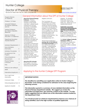
X-CORE Residential Irrigation ControllerRUNSYSTEM OFFSENSOR BYPASSCURRENT TIME/DAYACTIVEMANUAL-ONE STATIONSTART TIMESRUN TIMESSEASONAL ADJUSTMENTOwner’s Manual andProgramming InstructionsWATER DAYS
RUNSENSOR BYPASSSYSTEM OFFMANUAL SINGLE STATIONCURRENT TIME/DAYACTIVESTART TIMESRUN TIMESSEASONAL ADJUSTMENTWATER DAYS
TABLE OF CONTENTSX-CORE COMPONENTS.4MOUNTING THE CONTROLLER TO WALL.8CONNECTING VALVES AND TRANSFORMER.9ACTIVATING THE BATTERY. 10REPLACING THE BATTERY. 10CONNECTING A MASTER VALVE. 11CONNECTING A PUMP START RELAY.12CONNECTING A HUNTER “CLIK” WEATHER SENSOR.13Testing the Weather Sensor.13Manually Bypassing the Weather Sensor.13CONNECTING A HUNTER SOLAR SYNC ET SENSOR. 14Installing Solar Sync Sensor. 14Installing the Wireless Solar Sync . 14Solar Sync Settings. 14Region.15Water Adjustment.16Uninstalling a Solar Sync Sensor. 14Calibration/Setup.17SOLAR SYNCDELAY FEATURE.18CONNECTING A HUNTER REMOTE.19Connecting to a Hunter Remote (not included).19To install the SmartPort connector.19POWER FAILURES.19PROGRAMMING THE CONTROLLER.20Setting the Date and Time .21Setting the Program Start Time(s).21Eliminating a Program Start Time.21Setting Station Run Times .21Setting Days To Water.21Selecting Specific Days of the Week to Water.21Selecting Odd or Even Days to Water. 22Selecting Interval Watering.22Setting Event Day(s) Off. 22Automatic Watering .22System Off.22Programmable Rain Off. 23Seasonal Adjustment . 23Manually Run a Single Station 1 . 23One-Touch Manual Start and Advance.24ADVANCED FEATURES. 25Programmable Sensor Override. 25Test Program of All Stations. 25Hunter Quick Check Diagnostics. 25Easy Retrieve Program Memory.26Programmable Delay Between Stations.26Resetting Controller / Clearing Controllers Memory.26Clik Delay Instructions. 27TROUBLESHOOTING GUIDE.30SPECIFICATIONS. 33Operating Specifications. 33Electrical Specifications. 33Explanation of Symbols. 33CERTIFICATE OF CONFORMITY TO EUROPEAN DIRECTIVES.343
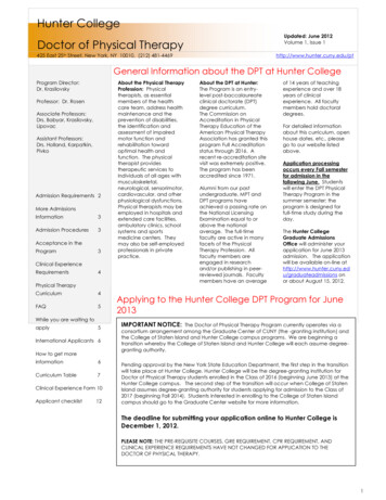
X-CORE COMPONENTSLCD Display1Run TimesAllows user to set each valve station run time from 1 minute to 4 hours2Start TimesAllows 1 to 4 start times to be set in each program3Station NumberIndicates currently selected station number4Program DesignatorIdentifies program (A, B, or C) in use5Day of the WeekIdentifies day of the week6Interval WateringIdentifies month when programming current date7Odd/Even WateringIdentifies if Odd or Even watering has been selected8Flashing SprinklerIndicates that watering is taking place9System OffAllows user to discontinue all programs and watering. Also allows the user to set the programmable“rain off,” which stops watering for a period from 1 to 7 days.10UmbrellaIndicates that the rain sensor is active11Seasonal AdjustmentAllows the user to make run time changes according to the seasons without reprogramming the controller.Bars on the left allow quick visual reference to the seasonal adjustment percentage. When using Solar SyncET Sensor, will display seasonal adjust updated daily by sensor.124Rain DropIndicates watering will occur on the selected day13Crossed Rain DropIndicates the watering will NOT occur on the selected day14CalendarIndicates interval watering schedule has been programmed. Icon also appears when programming thecurrent day
X-CORE COMPONENTSWiring Compartment15Lithium BatteryThe replaceable lithium battery (included) allows the controller to be programmed in the absenceof AC power. In addition, the battery will provide power for backup timekeeping in the event of apower outage.16Internal Junction BoxJunction box in outdoor models for making AC power connections17Terminal StripUse to attach transformer, sensor, and valve wires from their source to the controller18Reset ButtonUse to reset the controller (located on right side of controller)19REMAllows for connection of Hunter SmartPort and Hunter Remote Controls20Sensor Bypass SwitchIgnores “Clik” weather sensor input when in Bypass positionControl ButtonsButtonIncreases the selected item flashing in the displayButtonDecreases the selected item flashing in the displayButtonReturns selected flashing display to previous itemButtonAdvances the selected flashing display to the next item Button5Selects program A, B, or C for different watering zone requirements5
X-CORE COMPONENTSIndoor ModelOutdoor Model(Internal TransformerIncluded)Note: Plug maylook different fromillustration6Terminalblock for -E(Internationalmodels only)6
X-CORE COMPONENTSDial SettingsRun1Normal dial position for all controller automatic and manual operationCurrent Time/DayAllows current day and clock time to be setStart TimesAllows 1 to 4 start times to be set in each programRun TimesAllows user to set each valve station run time from 1 minute to 4 hoursWater DaysAllows the user to select interval days to waterSeasonal AdjustmentAllows user to make run time changes according to the seasons without reprogramming the controller.Bars on the left allow quick visual reference to the seasonal adjustment percentage.Manual-One StationAllows user to activate a one-time watering of a single valveSystem OffAllows user to discontinue all programs and watering. Also allows the user to set the programmable“rain off,” which stops watering for a period from 1 to 7 daysSOLAR SYNC SettingsAllows user to program settings when using Solar Sync ET SensorExternal Transformer (Indoor Model Only)A plug in transformer is provided to supply AC power to the controller7
MOUNTING THE CONTROLLER TO WALLNote: The indoor version of the X-Core is not waterproof or weather-resistant, and must be installed indoorsor in a protected area.BA1. Secure one screw into the wall. Install screw anchors if attachingto drywall or masonry wall.2. Slide the keyhole on top of the controller over the screw.3. Secure the controller in place by installing screws in the holesbelow the terminal strip.NOTE:Do not plug transformer into power source untilcontroller is mounted and all valve wiring hasbeen connected.NOTE: For XC - x01 - A: If the supply cord is damaged, itmust be replaced by the manufacturer or service agent,or a similarly qualified person in order toavoid hazard.NOTE: The door on outdoor units must remain closedfor maximum water resistance.C8
CONNECTING VALVES AND TRANSFORMERInstallation of the X-Core should only be done by trained personnel.Valve 41. Route valve wires between the control valve location and controller.2. At valves, attach a common wire to either solenoid wire on allvalves. This is most commonly a white colored wire. Attach aseparate control wire to the remaining wire of each valve. Allwire connections should be done using waterproof connectors.Valve 3BATValve 23. Route the valve wires through the conduit. Attach the conduitthrough the bottom right side of the controller.4. Secure the white valve common wire to the C (Common) screwon the terminal strip. Attach each of the individual valve controlwires to the appropriate station terminals and tighten theirscrews.Connect the two transformerwires to the two AC TerminalsNOTE: X-Core outdoor models are water andweather-resistant throughout document. Connectingthe outdoor X-Core to primary AC power should only bedone by a licensed electrician following all local codes.Improper installation could result in shock or fire hazard.Valve 1Valve Common Wire5. Indoor Models: route the transformer cable through the hole onthe left side of the controller and connect the wires to the twoscrews marked 24 VAC. Outdoor Models: transformer wires are already connected to theAC terminals so all that is required is to connect primary powerto the junction box (see below).ValveWiresHigh Voltage Wiring (Outdoor Model only)1. Route AC power cable and conduit through the ½" (13 mm)conduit opening on the left side bottom of the cabinet.2. Connect one wire to each of the two wires inside the junctionbox. The ground wire should be connected to the green wire.Wire nuts are provided to make these connections.Note: For –E models only: Connect the wires to the ACterminal block inside the junction box. AC supply wires mustbe 14 AWG (1.85 mm) or larger with appropriate circuit breakerfor the wire size. A switch or circuit-breaker shall be includedin the building installation (in close proximity to the controller,within easy reach of the operator) and marked as the disconnecting device for the equipment.3. Replace the junction box cover.9
ACTIVATING THE BATTERYAfter installing your X-Core, make sure to remove the batterycontact insulator to allow the X-Core to keep time in the event ofa power outage.CAUTION:RISK OF EXPLOSION IF BATTERY IS REPLACED BY ANINCORRECT TYPE. DISPOSE OF USED BATTERIES ACCORDING TO THE INSTRUCTIONS.REPLACING THE BATTERYA high-energy lithium battery is included with your X-Corecontroller. The battery allows the user to remotely program theLithium Batterycontroller without connecting AC power. It is also used to keepthe current time and day during power outage conditions.To replace the battery:Battery1. Remove the screw from the battery holder.2. Slide the battery holder down to access the battery.3. Remove and replace the new battery into the battery holderand reinstall the battery holder.NOTE: This positive( ) side of the battery should facethe inside of the battery holder.10(--)Battery Compartment( )SEN24VACHolderBATBattery type: CR2032 3VCP12345678
CONNECTING A MASTER VALVE1. A t the Master Valve, attach the common wire to either solenoidwire of the valve. Attach a separate control wire to the remainingsolenoid wire.NOTE: Complete this section only if you have amaster valve installed in your irrigation system. Amaster valve is a “normally closed” valve installed at thesupply point of the main line that opens only when thecontroller initiates a watering program.2. The common wire should be attached to the C terminal inside thecontroller. The other wire coming from the master valve shouldbe attached to the P terminal inside the controller. Tighten eachterminal screw.Valve 424VACBATSENCP12345678Valve 3MasterValve WireValve 2Valve 1Valve WiresMaster ValveValve Common Wire11
CONNECTING A PUMP START RELAYNOTE: Complete this section only if you have apump start relay installed. A pump start relay isa device that uses a signal from the controller toactuate a separate electrical circuit to energize a pumpto provide water to your system.The controller should be mounted at least a 15 ft (4.5 m) away fromboth the pump start relay and pump to minimize any potentialelectrical interference.1. Route a pair of wires from the pump relay into the controller.2. Connect a common wire to the C (common - typically a whitewire) terminal inside the controller and connect the remainingwire from the pump start relay to the P (Pump) terminal.Relay holding current draw must not exceed 0.3 A. Do not connectthe controller directly to the pump or damage to the controllerwill trollers/pumpstart-relayPSR SeriesPump Start RelayRUNSENSOR BYPASSSYSTEM OFFCURRENT TIME/DAYACTIVEMANUAL-ALL STATIONSALLSTART TIMESSTART TIMESRUN TIMESSEASONAL ADJUSTMENT15 ft Minimum (4.5 m)To Pump12WATER DAYS
CONNECTING A HUNTER “CLIK” WEATHER SENSORA Hunter weather sensor or other micro-switch type weathersensors can be connected to the X-Core. The purpose of this sensoris to stop automatic watering when weather conditions dictate.1. Remove the metal jumper plate that is attached across the twoSEN terminals inside the controller.2. Connect one wire to one SEN terminal and the other wire to theother SEN terminal.24VAC REMBATSENCP12345678When the weather sensor hasdeactivated automatic watering, theOFF, andicon will appear on thedisplay.Testing the Weather SensorThe X-Core provides simplified testing of a rain sensor when thesensor is wired into the sensor circuit. You can manually test properoperation of the rain sensor by running a AUTO CYCLE or byactivating the system using the One Touch AUTO CYCLE. Duringthe Manual cycle, pressing the Top spindle on the Mini-Clik willinterrupt watering.Manually Bypassing the Weather SensorIf the rain sensor is interrupting irrigation,you can bypass it by using the bypass switchBYPASSon the front of the controller. Slide the/DAYswitch to the SENSOR BYPASS position todisable the rain sensor from the system toACTIVEallow for controller operation. When usingthe MANUAL – ONE STATION function, thecontroller will automatically bypass sensor inputs for the selectedtime. Once complete, the controller will default to selected settings.NOTE: Enabling the Sensor Bypass switch has noeffect on the seasonal adjust updates from the SolarSync sensor. It will, however, bypass the Rain Clikand Freeze - Clik functionality of the sensor.13
CONNECTING A HUNTER SOLAR SYNC ET SENSORThe X-Core is compatible with the Solar Sync and Wireless SolarSync systems. Solar Sync is a sensor system that will automaticallyadjust the X-Core controller’s watering schedule (based on changesin local climate condition) by using the Seasonal Adjust function. TheSolar Sync uses a solar and temperature sensor to determine evapotranspiration (ET), or the rate at which plants and turf use water, andalso includes Hunter Rain Clik and Freeze Clik technology that willshut down irrigation when it rains and/or during freezing conditions.NOTE: Solar Sync will apply a default seasonal adjustvalue of 100% until the first full day (24 - hour period)of weather measurements have been received from thesensor.NOTE: Enabling the Sensor Bypass switch has no effecton the seasonal adjust updates from the Solar Sync sensor. It will, however, bypass the Rain Clik and Freeze Clikfunctionality of the sensor.NOTE: The Solar Sync module is not required forinstallation using the X-core Controller.Installing Solar Sync SensorConnect the Green and Black wire from the Solar Sync Sensor to the“SEN” wiring terminals on the X-Core controller, similar to pictureon page 11. It does not matter whichwire connects to which terminal. Turnthe dial to the “Solar Sync Settings”position. The display will initially showdashed lines and then will show thedefault Region setting (3) on the left14and the default Water Adjustment setting (5) on the right. Adjustthe Region as needed by using theandbuttons . Use thebutton to advance to the right to adjust the Water Adjust setting asneeded (see page 14 for explanation of Water Adjust setting).Installing the Wireless Solar SyncConnect the Green and Black wire from the Wireless Solar SyncReceiver to the “SEN” wiring terminals on the X-Core controller. Itdoes not matter which wire connects to which terminal. Turn the dialto the “Solar Sync Settings” position. The display will initially showdashed lines and then will show the default Region setting (3) onthe left and the default Water Adjustment setting (5) on the right.andbuttons (refer toAdjust the region as needed by using thepage 15 for explanation of Solar SyncRegion setting). Use the buttonto advance to the right to adjust theWater Adjust setting as needed (seepage 16 for explanation of WaterAdjust setting).Solar Sync SettingsOnce the Solar Sync sensor is connected to the X-Core controller,two numbers will appear in the display when the dial is turned to theSolar Sync Settings position. The number on the left of the screen isthe Region setting, and the number on the right on the screen is theWater Adjustment setting (as shown above).
CONNECTING A HUNTER SOLAR SYNC ET SENSORRegionFor accurate Solar Sync measurements, the controller needs tobe programmed for the average peak season ET for your region. Usethe table below to determine your region.The table will assist you in identifying the type of region you livein. There are four basic ET regions, each with descriptions of theregion, along with typical ET and temperature characteristics. It isrecommended that, if possible, the region be chosen based uponaverage July ET or peak summer ET (inches/mm per day).Use the following table for choosing your region (reference below).You can use methods A, B or C to help you choose which region isbest for your area:A: Based upon the ET of your region using the average July ETor peak summer ET (inches/mm per day). This is the preferredoption when selecting your region.B: Based upon the temperature for your region using the averageJuly or the driest month high temperature (not the highesttemperature for July).C: Based upon the general description of your region.IF ANY OF THE CHOICES IN THE ROWS APPLY TO YOUR SITUATION, THEN THAT IS YOUR REGION SETTING CHOICE.ABC1If the average July ET is 0.17" (4.3 mm) per dayIf the average temperature for July is65 – 75 (18 C – 24 C) U.S. Northern States Coastal RegionsRegion2If the average July ET is 0.18" – 0.23"(4.6 mm – 5.8 mm) per dayIf the average temperature for July is75 – 85 (24 C – 29 C) Mountains U.S. Northern Inland StatesRegion3If the average July ET is 0.24" – 0.29"(6.1 mm – 7.4 mm) per dayIf the average temperature for July is85 – 95 (29 C – 35 C) U.S. Southern States Inland/High DesertRegion4If the average July ET is 0.30"(7.6 mm) per dayIf the average temperature for July is95 – 105 (35 C – 41 C) DesertsRegion* For Southern hemisphere locations, use the month of January.15
CONNECTING A HUNTER SOLAR SYNC ET SENSORWater AdjustmentUninstalling a Solar Sync SensorThe Water Adjustment is a 1 to 10 scale that allows for easyadjustment of the Seasonal Adjust value from the Solar SyncET Sensor. Upon installation of the Solar Sync ET Sensor, it isrecommended that the Water Adjustment setting stay at the defaultvalue of 5. However, after installation, if you find that the seasonaladjust value is lower or higher than expected, the Water Adjustmentvalue can be modified to modify the Seasonal Adjust output value.See Calibration/Setup on page 17 for explanation of how to useWater Adjustment scale to fine - tune seasonal adjust output value.If a Solar Sync sensor has been installed on the X-Core controller,then the seasonal adjust value used by the controller will becalculated from the weather data supplied by the Solar Sync sensor.If it is decided that the Solar Sync sensor will no longer be usedwith the X-Core controller, it must be uninstalled. If the Solar Syncsensor is not uninstalled, the controller will not allow the seasonaladjust value to be manually changed. For example, if the seasonaladjust value shown on the controller was 50% when the Solar Syncsensor was removed, it will remain 50% until the Solar Sync sensor isuninstalled.NOTE: If an individual zone is “wetter” or “drier” thanthe rest of the system, simply increase ordecrease the amount of run time on the controller.16To uninstall the Solar Sync sensor, simply disconnect the green andblack wires from the controller terminal and then turn the dial tothe “Solar Sync Settings” position. The display should show dashes,indicating that the controller no longer recognizes the Solar Syncsensor for calculation of seasonal adjustment. Now the seasonaladjust value can be changed manually by turning the knob to the“Seasonal Adjust” position and using theorbutton to adjustthe value.
CONNECTING A HUNTER SOLAR SYNC ET SENSORCalibration/SetupAfter Solar Sync has been installed and programmed, it is recommended to allow the system to run for a few days at the initial setting.Because of the variety in site conditions (including sensor location, amount of direct sunlight available to the sensor, reflective heat fromsurrounding structures, etc), the initial setting may require adjustment in order to arrive at the desired performance. The calibrationof the Solar Sync to a particular site can easily be accomplished by adjusting the Region and/or Water Adjustment settings. The instructionsbelow outline this process:1. Install Solar Sync sensor2. Program Region and allow system to operate at initial setting for a minimum of 3 days (see page 15 for instructions on how to determineproper Region setting).3. Observe the Seasonal Adjust on the controller. If the Seasonal Adjust amount appears to be lower or higher than expected for that time ofyear, the Solar Sync settings need to be adjusted.a. Seasonal Adjust too low: Turn the dial to the Solar Sync settings position. Increase the value on the Water Adjustment scale (10 is max). Oncethe setting is changed, the controller will immediately be updated with the new Seasonal Adjust %. Increase the Water Adjustment settinguntil the desired Seasonal Adjust % is shown. If you max out the Water Adjustment scale at 10 and still require more Seasonal Adjust, movedown to the next lower Region (from Region 4 to 3, for example).b. Seasonal Adjust too high: Turn the dial to the Solar Sync settings position. Decrease the value on the Water Adjustment scale (default settingis 5). Once the setting is changed, the controller will immediately be updated with the new Seasonal Adjust %. Decrease the Water Adjustmentsetting until the desired Seasonal Adjust % is shown. If you minimize the Water Adjustment scale down to 1 and still require a reduction inSeasonal Adjust, move up to the next Region (from Region 2 to 3, for example).Station Run Times: It is important to understand that Solar Sync provides a global seasonal adjustment to the controller. This means thatall station run times will be modified by the seasonal adjust percentage shown. When programming the controller, the run times should beentered that represent peak season watering schedules. If the Solar Sync is adjusting to the appropriate seasonal adjust value but the run timefor a particular station appears to be too long/short, adjust the station run time in the controller program.17
SOLAR SYNC DELAY FEATURESolar Sync Delay for X-CORE To change the existing Delay days setting:The delay feature is accessible only after the installationof the Solar Sync. The Solar Sync Delay feature allows the user topostpone seasonal adjustment changes from being madeby Solar Sync for up to 99 days.1. Open the Solar Sync Delay menu by pressing thebutton androtating the dial to Solar Sync Settings and release thebutton.While the Solar Sync Delay is active, the Solar Sync will continue tocollect and store data.Operation:To access the Solar Sync Delay setting:1. Place the dial in the RUN position; press and hold thebutton,rotate the dial to the Solar Sync position then release thebutton. The following screen will be presented: d:XX (where dindicates days and XX indicates the number of daysto be delayed).2. Press theorbutton to increase/decrease the numberof days the delay should run. Once the desired number of daysis displayed, move the dial back to the RUN position to activatethe delay.NOTE: The number of days remaining will not bedisplayed on the RUN screen. To check if the Delayfeature is active, open the Solar Sync Delay menuand check the days displayed. If 1 or more days aredisplayed, then Solar Sync Delay is active, if 00 isdisplayed, then Solar Sync Delay is not active.182. Use the or - keys to modify the number of days until desirednumbers of delay days is displayed. (Setting the days to 00 turnsSolar Sync Delay to OFF.)3. Return the dial to the RUN position for the changes totake effect.While Solar Sync Delay is active, the Solar Sync will continueto gather weather information and calculate the SeasonalAdjust Value. The updated seasonal adjust will be applied once theSolar Sync Delay days reach 00.
CONNECTING A HUNTER REMOTEConnecting to a Hunter Remote (not included)housing into the “Tee” as shown.The X-Core Controller is compatible with Hunter Remote Controls(not included). The SmartPort wiring harness (included with allHunter Remotes) allows for fast and easy use of the Hunter controls.The Hunter remotes make it possible for you to operate the systemwithout having to walk back and forth to the controller. Red wire to left side “24 VAC” terminal White wire to right side “24 VAC” terminal Blue wire to “REM” terminalTo install the SmartPort connector1. Install a 1/2" Female threaded “Tee” inthe field wiring conduit (not included)approximately 12 inches below theX-Core.4. Attach the red, white, and blue SmartPort wires to thecontroller terminal as shown below:To Controller1/2"24VACSENCP12345678Thread2. Feed the red, white, and blue wiresof the harness through the base ofthe “Tee” and into the wiringcompartment as shown.3. Screw the SmartPort harnessPre-assembledAssembledred bluewhiteNOTE: P/N 258200 can be used asan alternate method to mount theSmartPort connector.POWER FAILURESDue to the possibility of power failures, the controller has non-volatile memory. Programmed information will never be lost due to a poweroutage. The lithium battery will keep the correct time without AC power. Normal watering will resume when AC power is restored.19
PROGRAMMING THE CONTROLLERThe X-Core display shows the time and day when the controller isidle. The display changes when the dial is rotated to indicate thespecific programming information to enter. When programming, theflashing portion of the display can be changed by pressing theorbuttons. To change something that is not flashing, press theor buttons until the desired field is flashing.Three programs A, B, and C, each with the ability to have four dailystart times, permit plants with different watering requirements to beseparated on different day schedules.NOTE: A basic programming rule is that whateversymbol or character is flashing will be the itemprogrammed. For instance, if the hour is flashingwhen setting the time, the hour can be changed orprogrammed. For illustration purposes in this manual,flashing characters are in GRAY type.CURRENT TIME/DAYSetting the Date and Time1. Turn the dial to the CURRENT TIME/DAY position.2. The current year will be flashing. Use theorbuttons tochange the year. After setting the year, press the button toproceed to setting the month.3. The month and day will be in the display. The month will be flashing and theicon will be displayed. Use theorbuttons to change the month. Press the button to proceedto setting the day.12icon will be displayed. Use4. The day will be flashing and thetheorbuttons to change the day. Press the button toproceed to setting the time.5. The time will be displayed. Use theandbuttons to selectAM, PM, or 24 hour. Press the button to move to hours. Hourswill be flashing. Use theandbuttons to change the hourshown on the display. Press the button to move to minute.Minutes will be flashing. Use theandbuttons to changethe minutes shown on the display. The date, day, and time havenow been set.2031
PROGRAMMING THE CONTROLLERSetting the Program Start Time(s)1. Turn the dial to the START TIMES position.START TIMES2. The factory preset is set on program A. Ifnecessary, you can select program B, or Cby pressing the button.minute increments).buttonNOTE: One start time will activate all stations sequentiallyin that program. This eliminates the need to enter eachstation’s start time. Multiple start times in a program can beused for separate morning, afternoon, or evening wateringcycles. Start times may be entered in any order. The X-Corewill automatically sort them.Eliminating a Program Start TimeWith the dial set to START TIMES position,push theorbutton until you reach 12:00AM (Midnight). From h
X-CORE COMPONENTS LCD Display 1 Run Times Allows user to set each valve station run time from 1 minute to 4 hours 2 Start Times Allows 1 to 4 start times to be set in each program 3 Station Number Indicates currently selected station number 4 Program Designator Identifies program (A, B, or C) in use 5 Day of the Week Identifies day of the week 6 Interval Watering Identifies month when .