Transcription
NODEENBattery-Operated ControllerESProgramador de pilasFRProgrammateur à pilesITProgrammatore a batteriaDEBatteriebetriebenes SteuergerätPTControlador de Funcionamento a PilhasTRPilli Kontrol ÜnitesiOwner’s manual and programming instructionsManual del usuario e instrucciones de programaciónManuel de l'utilisateur et consignes de programmationManuale dell’utente e istruzioni per la programmazioneBedienungs- und ProgrammieranleitungManual do Proprietário e Instruções de UtilizaçãoKurulum, Programlama ve Kullanım Kılavuzu
TABLE OF CONTENTSNODE FEATURES . . . . . . . . . . . . . . . . . . . . . . . . . . . . . . . . . . . . . . . . . . . . . . . . 2NODE COMPONENTS . . . . . . . . . . . . . . . . . . . . . . . . . . . . . . . . . . . . . . . . . . . . 3Control ButtonsLCD DisplayCONNECTING THE BATTERY/BATTERIES. . . . . . . . . . . . . . . . . . . . . . . . . . 4ATTACHING SOLENOIDS . . . . . . . . . . . . . . . . . . . . . . . . . . . . . . . . . . . . . . . . . 5To Wire DC Solenoids to the NODETo Mount the NODE to a Valve (Figure 1)MOUNTING THE NODE. . . . . . . . . . . . . . . . . . . . . . . . . . . . . . . . . . . . . . . . . . . 6CONNECTING A WEATHER SENSOR. . . . . . . . . . . . . . . . . . . . . . . . . . . . . . . 6Setting the Date and TimeIDLE MODE . . . . . . . . . . . . . . . . . . . . . . . . . . . . . . . . . . . . . . . . . . . . . . . . . . . . . 7RUN MODE. . . . . . . . . . . . . . . . . . . . . . . . . . . . . . . . . . . . . . . . . . . . . . . . . . . . . . 7PROGRAMMING. . . . . . . . . . . . . . . . . . . . . . . . . . . . . . . . . . . . . . . . . . . . . . . . 7Setting Watering Start TimesSetting the Run TimesSetting Watering DaysSelecting Odd/Even Days to WaterSelecting Interval Days to WaterSetting the Seasonal AdjustmentTurning the System OffManual WateringSensor OperationADVANCED PROGRAMMING FEATURES. . . . . . . . . . . . . . . . . . . . . . . . . . 12Sensor BypassEasy Retrieve MemorySetting Master Valve Operation (NODE-200, NODE-400,& NODE-600 Only)Programmable Off (Up to 99 Days)1ENBATTERY-LIFE INDICATOR . . . . . . . . . . . . . . . . . . . . . . . . . . . . . . . . . . . . . .RESETTING CONTROLLER. . . . . . . . . . . . . . . . . . . . . . . . . . . . . . . . . . . . . . .TROUBLESHOOTING GUIDE . . . . . . . . . . . . . . . . . . . . . . . . . . . . . . . . . . . . .SPECIFICATIONS . . . . . . . . . . . . . . . . . . . . . . . . . . . . . . . . . . . . . . . . . . . . . . .NOTES. . . . . . . . . . . . . . . . . . . . . . . . . . . . . . . . . . . . . . . . . . . . . . . . . . . . . . . . .1414151617
NODE FEATURES Simple push-button programming Single-station model (NODE-100) with DC latching solenoid. Single-, two-, four-, or six-station models are also available(solenoids not included). Large Liquid Crystal Display (LCD) with easy-to-understand icons Operates using at least one standard nine-volt alkaline battery (use two for extended battery life) Three programs (A, B, or C) with up to four start times each Run times from one minute to six hours Manual watering capabilities Battery-life indicator Wired rain sensor compatible Non-volatile memory retains all program information Seasonal Adjustment from 10–150% Easy Retrieve memory allows saving/retrieval of preferred program data Manual bypass of rain sensor Total Run Time Calculator shows total program irrigation time per programEN2
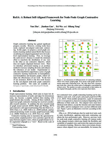
NODE COMPONENTSENThis section provides an overview of some of the components of theNODE. Each item will be discussed in further detail later. However, thissection can be helpful in getting acquainted with the different optionsavailable.34111214 15131LCD Display1.Main Display – Indicates all program information2. Station Number – Indicates the station number being programmed3. Start Time Number – Indicates the start timer number beingprogrammed4. Program – Indicates the program (A, B, or C)10596782Control Buttons1.Button – Increases the selected flashing display2.Button – Decreases the selected flashing display3.Button – Selects programming function4.5.6.3Button – Advances the selected flashing display back to thenext itemButton – Navigates the selected flashing display back to theprevious itemButton – Selects the program (A, B, or C)5.6.Current Time/Day – Indicates when current day/time isbeing setStart Times – Indicates when start times are being set7.Run Times – Indicates when Run Times are being set. Allowsuser to set run times from one minute to six hours.8.Watering Days – Allows the user to select individual days towater or a selected number of days between watering (interval)9. % Seasonal Adjustment – Allows the seasonal adjustment to beprogrammed form 10–150% (default value is 100%)10.11.System Off – Indicates that watering is suspendedManual On/Off – Indicates when manual watering isprogrammed. Allows the user to activate the station manually.12. MV – Indicates that station one is set to master valve operation(only available on two-, four-, or six-station models)13.Battery Status – Indicates remaining battery life14.Umbrella – Indicates the rain sensor is suspending irrigation15.Crossed Umbrella – Indicates the rain sensor has beenmanually bypassed
CONNECTING THE BATTERY/BATTERIESThe NODE uses one or two standard nine-volt batteries (not included)to operate the valves and program the controller. The controller canoperate using either a single nine-volt battery or using two nine-voltbatteries. Under normal conditions, the expected life is one year for asingle battery and two years when using two nine-volt batteries.ENTo Install the Battery/Batteries1.Unscrew the rear body of the NODE body to gain access to thebattery compartment.2. Insert the battery/batteries into the battery tray and connect tothe controller using the battery connector.3. Make sure that no water is inside the battery compartment.NOTE: The NODE has non-volatile memory. Thisallows the battery to be removed without losingprogram information.4. Screw the NODE rear body back onto the front half.NOTE: Verify that the seal marker on the rear halfof the NODE lines up with the front half, ensuringthat a proper seal is created.4
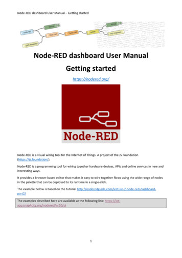
ATTACHING SOLENOIDSThe NODE-100 is provided with a solenoid attached to the controller.The NODE-100-LS does not include a solenoid. The NODE-200,NODE-400, and NODE-600 multi-station controllers will operate up totwo, four, or six solenoids, respectively. Hunter DC-latching solenoids(P/N 458200) can easily be installed on all Hunter plastic valves.NOTE: Use DC latching solenoids operatingbetween 9-11 VDC. 24 VAC solenoids will notoperate with the NODE.ENTo Wire DC Solenoids to the NODE1.Attach the black leads from each solenoid to the single commonwire (black lead) coming from the NODE. Secure all wireconnections with waterproof connectors.2. Attach one red wire from each solenoid to the correspondingstation wire (red lead) from the NODE. The station numbers areidentified on the face of the NODE. Secure all wire connectionswith waterproof connectors.NOTE: The maximum wire distance between thesolenoid and NODE is 100' (30 m) using 18 AWG(1 mm) minimum wire size.Common Wire (Black Leads)Station Wire (Red Leads)5
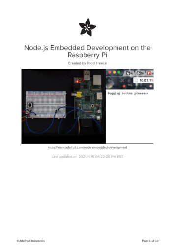
MOUNTING THE NODECONNECTING A WEATHER SENSORThe NODE can easily be mounted on any Hunter plastic valve. Aspecially designed valve mounting clip makes installation a snap. Aprotective rubber cover is provided to prevent dirt from accumulatingon the face of the NODE.A Hunter Mini-Clik or Wired Rain-Clik rain sensor can be connectedto the NODE. The purpose of this sensor is to stop watering whenweather conditions dictate.NOTE: When the Wired Rain Sensor is interruptingthe watering, the display will show the System Officon, “OFF” andon the display.To Mount the NODE to a Valve (Figure 1)1. Screw the Hunter DC latching solenoid (P/N 458200) intothe valve bonnet.2. Set the small open end of the NODE holder on top of the solenoid.3. Set the NODE controller into the large open end of theNODE holder.NODE holderEN1.Cut the yellow wire loop attached to the NODE at approximatelythe middle of the loop.2. Remove approximately ½" (13 mm) of insulation from each wire.Attach one yellow wire to each of the wires of the weather sensor.You can mount the rain sensor up to 100 ft (30 m) from the NODEcontroller (18 AWG/1 mm minimum wire size).3. Secure wire connections with waterproof connectors.Figure 1Hunter Model Mini-Clik 6
IDLE MODEPROGRAMMINGNormally, the NODE display shows the time and day, day of theweek, MV (if master valve option is activated), and the battery-lifeindicator. After a short period of inactivity, the display will shut off toretain battery power. Pressing any button will bring the NODE intoidle mode.The NODE uses standard Hunter controller programming with threeprograms (A, B, or C) and four start times per program. On standardHunter controllers a dial is used to scroll between the programmingfunctions. However, on the NODE thebutton is used to quicklyand easily create the irrigation program. When programming, theflashing portion of the display can be changed by pressing theorbuttons. To change something that is not flashing, press theorbuttons until the desired item is flashing.ENSetting the Date and Time1.RUN MODEWhen the controller is operating a program, the items shown on thedisplay will include the station number, program letter, remainingrun time, and the blinking Rotor icon.Push thebutton until theicon is displayed.2. All four digits will be displayed representing the year. Use theorbuttons to change the year. Press thebutton to proceedto setting the month.3. All four digits will be displayed with the two digits on the leftorbuttons torepresenting the month flashing. Use thechange the month. Press thebutton to proceed to settingthe day.4. Only the two digits on the right side will be displayed and flashing,orbuttons to change therepresenting the day. Press theday. Press thebutton to proceed with changing the hour. Pressthebutton to proceed to setting the time.5. The AM/PM/24-hour time setting is shown flashing. Press theorbutton to change the time setting to AM, PM, or 24-hourtime. Press thebutton to proceed to setting the hour.7
PROGRAMMING (CONTINUED)EN6. All four numbers are shown with the two numbers on the leftflashing, representing the hour. Use theorbuttons tochange the hour. Press thebutton to proceed to settingthe minutes.7. All four numbers are shown with the two numbers on the rightorbuttons toflashing, representing the minutes. Use thechange the minutes. Pressing thebutton will advanceto the year setting at Step 2.NOTE: After programming the run time for the laststation press thebutton to display the total runtime for the program.button to proceed to the next programming function8. Press theor allow controller to return to idle mode.Setting the Run Times1.Setting Watering Start Times1.Press thebutton until theicon is displayed.2. The start time will be displayed flashing, along with the programletter (A, B, or C) and the start time number (1, 2, 3, or 4) in theupper left of the display. Up to 4 different start times can be set foreach program.orbuttons to change the start time for the program3. Use thethat is displayed. Each press of the button will change the starttime in one-minute increments.Press thebutton until theicon is displayed.2. The run time will be displayed flashing. Also shown is the programletter (A, B, or C) and the active station number on the lowerorbuttons to change theleft side of the display. Press thestation run time from one minute to six hours.3. Press thebutton to advance to the next station.4. Press thebutton to add a run time to another program.button to proceed to the next programming function5. Press theor allow controller to return to idle mode.button to add an additional start time to the program4. Press thedisplayed. The start time number is shown in the upper left cornerof the display.5. Press thebutton to add start times to a different program.button to proceed to the next programming function6. Press theor allow controller to return to idle mode.8
PROGRAMMING (CONTINUED)ENSetting Watering Days1.Press thebutton until theicon is displayed.2. The program letter (A, B, or C) will be displayed.3. Arrows point at the specific days of the week on which wateringorbuttons to scroll though the days.will occur. Press thebutton to activate that day for the program displayed, or4. Press thethebutton to cancel watering for that day. The arrow will showon the watering days for the active program.5. Press thedesired.button to set days to water for a different program, ifbutton to proceed to the next programming function6. Press theor allow controller to return to idle mode.Selecting Interval Days to Water1.Press the2. Press thebutton until theOicon is displayed.button until the cursor is above INT on the display.button and a 1 will be flashing, indicating the number3. Press theof days between watering.orbuttons to select the number of days between4. Press thewatering days (1 to 31).Selecting Odd/Even Days to WaterThis feature uses numbered days of the month for watering instead ofspecific days of the week.1.Press thebutton until theicon is displayed.button until the cursor is above either ODD or EVEN2. Press theon the display.button to select, or the3. Press theODD or EVEN days to water.button to cancel either4. Once ODD or EVEN mode is activated, it will be the only cursorshown on the display.9Setting the Seasonal Adjustment1.Press thebutton until theINTis displayed.orbutton to increase or decrease the seasonal2. Press theadjustment value from the default 100% (down to a minimum of10% or a maximum of 150%).3. The value programmed for seasonal adjustment will be applied toall irrigation programs and will immediately be reflected inthe run times displayed. For example, if 20-minute run times areprogrammed and then the seasonal adjustment is changed from100% to 50%, the run times displayed will be 10 minutes.
PROGRAMMING (CONTINUED)EN4. To manually activate a program, press thebutton. The programletter (A, B, or C) will show on the screen. If a different programis needed, press thebutton until the desired program isdisplayed.Turning the System OffTo turn your controller off, press thebutton until theiconand OFF is displayed on screen. To return the controller to autoprogramming mode, press thebutton. The controller willimmediately return to auto programming mode and will display thetime and battery-life indicator.Manual WateringManual Watering allows the user to test each station or a programfor a specified run time. The weather sensor condition (if used) will bedisregarded in this mode.1.Make sure the controller is in idle mode. Press and hold thebutton until the icon is displayed.2. The station number will be displayed in the lower left side of thedisplay along with the run time.5. To stop the Manual Watering cycle, press thetime is reduced to zero.button until thebutton to proceed to the next programming function6. Press theor allow controller to return to idle mode.NOTE: Pressing theorbuttons when a station isrunning in Manual Watering mode will modify theirrigation time for that station. Pressing thebutton when a station is running inManual Watering mode will stop irrigation on thecurrent station and advance to the next station. Pressing thebutton when a station is running inManual Watering mode will stop irrigation on thecurrent station and revert to the previous station.andbuttons to select the desired station and3. Use thetheandbuttons to set the manual watering time for thestation shown.10
PROGRAMMING (CONTINUED)ENSensor OperationThe NODE is compatible with Hunter Clik-type rain sensors, includingMini-Clik , Freeze-Clik, and Wired Rain-Click , as well as many otherinterrupt-type devices/sensors that do not require power. Simplyconnect the sensor to the NODE controller by cutting the yellow wireloop and connecting to the sensor wires.NOTE: NODE is not compatible with HunterWireless Rain-Clik or other weather devices thatrequire 24 VAC power.When the sensor is activated, it will suspend irrigation and thewill show on the display.11icon
ADVANCED PROGRAMMING FEATURESENAll advanced programming functions are initiated from the idle mode,which shows the time, day of the week, and battery-life indicator onthe display. If something is flashing on the display then the controller isin one of the programming modes. After a short period of inactivity thecontroller will return to idle mode.Easy Retrieve MemorySensor BypassTo save a program:1.From the idle mode, press and hold theis displayed.button until theicon2. The display will show the umbrella icon flashing and ON.3. Press thebutton to bypass the sensor. The display will showand OFF to indicate the weather sensor is bypassed.Theicon will show on the display during normal operation,indicating the controller is in bypass mode.This function allows the user to save a preferred program to permanentmemory in the controller, which can be restored at any time. This is agreat way to override changes made, and revert back to the originalprogramming schedule.1.Make sure that the controller is programmed with the preferredprogramming schedule.2. From idle mode, press and hold theandseconds to save the current program.button for five3. The screen will show three dashed lines moving from left to rightto indicate the current program is being saved to permanentmemory. The display will flash DONE when the process iscomplete.To retrieve a saved program:1.4. To reactivate the weather sensor, press and hold thebuttonuntil theicon is displayed. Press thebutton to return tonormal sensor mode.From idle mode, press and hold theseconds.andbutton for five2. The screen will show three dashed lines moving from right toleft to indicate the preferred program is being retrieved frommemory.The controller now has the preferred program as the current program.The display will flash DONE when the process is complete.12
ADVANCED PROGRAMMING FEATURES (CONTINUED)NOTE: Be careful when using Easy Retrievememory. Saving program data to memory usingEasy Retrieve will take the current programinformation and override whatever is saved inpermanent memory. When saving program data,make sure that the current program data is whatyou want saved.The multi-station NODE models (NODE-200, NODE-400, andNODE-600) can be programmed with the use of a normally closedmaster valve. When programming with the master valve you will beassigning Station 1 as the master valve, effectively losing the use ofStation 1 for activation of an irrigation station.From the idle mode, press theis displayed.button until the3. Press thebutton once and the MV icon will display on thescreen and the time will disappear. Station 1 is now acting asthe master valve and will not be available in other programmingscreens.4. When the master valve is activated, it will apply to all programsand the MV icon will stay displayed on the screen at all times.Programmable Off (Up to 99 Days)Setting Master Valve Operation(NODE-200, NODE-400, & NODE-600 Only)1.ENicon2. Program A will be displayed along with the active station numberon the lower left. Make sure the active station showing is "1." Therun time will be shown.This feature permits the user to stop all programmed watering for thedesignated period from 1-99 days. At the end of the programmable offperiod, the controller will resume normal operation.1.From idle mode, press thebutton until theicon isdisplayed. Wait two seconds until OFF is shown on the display.The controller is now in System Off mode.button and a blinking "1" will be displayed, indicating2. Press thethe number of days the controller will stay off. Program the offdays as desired, up to 99 days maximum.3. The display will show the number of days remaining in theOFF period.button to return to the4. To interrupt the OFF period, press theidle mode screen, showing the time of day and day of the week.13
BATTERY-LIFE INDICATORRESETTING CONTROLLERThe remaining battery life can be estimated from the battery-lifeindicator shown on the display. The NODE can operate using eithera single nine-volt battery or using two nine-volt batteries. Using twonine-volt batteries will yield approximately twice the battery life of asingle nine-volt battery. The battery-life indicator chart below showsan estimate on the remaining battery life.Resetting the controller will erase the current program data and restartthe controller. A reset does not, however, delete a program saved topermanent memory using the Easy Retrieve memory feature (seepage 12) to save a preferred program.1.From idle mode, press and hold the,, andENkeys.Full: 100–60% remaining battery life2. After two seconds the screen will go blank. Continue to hold,, andkeys.theMed: 60–25% remaining battery life3. 12:00 will flash on the display. Release the keys.Low: 25–0% remaining battery life4. The controller may show a countdown from 10 to 1 on the display,and then 12:00 am will be shown flashing when the reset iscomplete. The controller can now be reprogrammed.Replace battery immediately!14
TROUBLESHOOTING GUIDEENProblemCausesSolutionsThere is no display.Display is off.Battery is dead.Press any button for one second.Replace the battery.Display indicates watering butnone is occurring.No water pressure.Faulty solenoid.Incompatible solenoid.Turn on main system supply.Replace solenoid.Must use Hunter DC latching solenoid (P/N 458200) orother compatible DC latching solenoid.Automatic irrigation does notstart at start time.Controller in System Off mode.Verify that controller is programmed forautomatic watering.Correct AM/PM/time of day.Correct AM/PM/start time.AM/PM/time of day not set correctly.AM/PM/start time not set correctly.Rain sensor does not suspendwatering.Rain sensor defective or miswired.Verify proper operation of the rain sensor and wireconnections (see page 11).Controller waters more than onetime.The program has more than one start timeassigned to it. Each program has up to fourstart times.Eliminate program start times as needed.SPECIFICATIONSDimensions: 3 ½"(89 mm) diameter, 2 ½"(64 mm) highSensor inputs: OnePower source: One nine-volt alkaline battery (use two for extendedbattery life). Activates DC latching solenoids operating 9-11VDC(Hunter PN 458200).Operating temperature: 0ºF to 140ºF (-17ºC to 60ºC)15Approvals:IP68CEFCCC-Tick
Hunter Industries Incorporated1940 Diamond Street San Marcos, California 92078, USAwww.hunterindustries.com/global16 2018 Hunter Industries IncorporatedLIT-560C6/18
The NODE-200, NODE-400, and NODE-600 multi-station controllers will operate up to two, four, or six solenoids, respectively . Hunter DC-latching solenoids (P/N 458200) can easily be installed on all Hunter plastic valves . NOTE: Use DC latching solenoids operating between 9-11 VDC. 24 VAC solenoids will not operate with the NODE. 1 .