Transcription
ltimeterContractorMultimeterUser ManualAM-520-EUREN FR ESAM-530-EURDigital Multimeter
AM-520HVAC MultimeterAM-530User Manual10/2017, Rev.4 2017 Amprobe Test Tools.All rights reserved. Printed in ChinaEnglishTrue-rms ElectricalContractor Multimeter
Limited Warranty and Limitation of LiabilityYour Amprobe product will be free from defects in material and workmanship for one year fromthe date of purchase unless local laws require otherwise. This warranty does not cover fuses,disposable batteries or damage from accident, neglect, misuse, alteration, contamination, orabnormal conditions of operation or handling. Resellers are not authorized to extend any otherwarranty on the behalf of Amprobe. To obtain service during the warranty period, return theproduct with proof of purchase to an authorized Amprobe Service Center or to an Amprobedealer or distributor. See Repair Section for details. THIS WARRANTY IS YOUR ONLY REMEDY.ALL OTHER WARRANTIES - WHETHER EXPRESS, IMPLIED OR STATUTORY - INCLUDING IMPLIEDWARRANTIES OF FITNESS FOR A PARTICULAR PURPOSE OR MERCHANTABILITY, ARE HEREBYDISCLAIMED. MANUFACTURER SHALL NOT BE LIABLE FOR ANY SPECIAL, INDIRECT, INCIDENTALOR CONSEQUENTIAL DAMAGES OR LOSSES, ARISING FROM ANY CAUSE OR THEORY. Sincesome states or countries do not allow the exclusion or limitation of an implied warranty or ofincidental or consequential damages, this limitation of liability may not apply to you.RepairAll Amprobe returned for warranty or non-warranty repair or for calibration should beaccompanied by the following: your name, company’s name, address, telephone number, andproof of purchase. Additionally, please include a brief description of the problem or the servicerequested and include the test leads with the meter. Non-warranty repair or replacement chargesshould be remitted in the form of a check, a money order, credit card with expiration date, or apurchase order made payable to Amprobe.In-warranty Repairs and Replacement – All CountriesPlease read the warranty statement and check your battery before requesting repair. During thewarranty period, any defective test tool can be returned to your Amprobe distributor for an exchangefor the same or like product. Please check the “Where to Buy” section on amprobe.com for a listof distributors near you. Additionally, in the United States and Canada, in-warranty repair andreplacement units can also be sent to an Amprobe Service Center (see address below).Non-warranty Repairs and Replacement – United States and CanadaNon-warranty repairs in the United States and Canada should be sent to an Amprobe ServiceCenter. Call Amprobe or inquire at your point of purchase for current repair and replacement rates.USA:AmprobeEverett, WA 98203Tel: 877-AMPROBE (267-7623)Canada:AmprobeMississauga, ON L4Z 1X9Tel: 905-890-7600Non-Warranty Repairs and Replacement – EuropeEuropean non-warranty units can be replaced by your Beha-Amprobe distributor for a nominal charge.Please check the “Where to Buy” section on beha-amprobe.com for a list of distributors near you.Beha-AmprobeDivision and reg. trademark of Fluke Corp. (USA)Germany*In den Engematten 1479286 GlottertalGermanyPhone: 49 (0) 7684 8009 - 0beha-amprobe.deUnited Kingdom52 Hurricane WayNorwich, NorfolkNR6 6JB United KingdomPhone: 44 (0) 1603 25 6662beha-amprobe.comThe Netherlands - Headquarters**Science Park Eindhoven 51105692 EC SonThe NetherlandsPhone: 31 (0) 40 267 51 00beha-amprobe.com*(Correspondence only – no repair or replacement available from this address. European customers pleasecontact your distributor.)**single contact address in EEA Fluke Europe BV
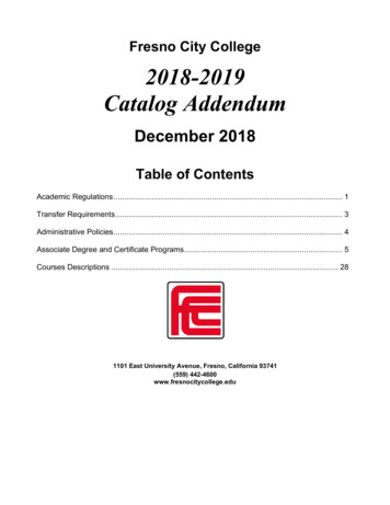
AM-520 HVAC MultimeterAM-530 True-rms Electrical Contractor Multimeter123465107981 Flash light4 Flash light Button2 LCD Display5 Rotary Switch3 Function Buttons6 SELECT Button7 Input Terminal for voltage, diode, capacitance,Resistance, continuity and temperature measurement8 COM (return) terminal for all measurements9 Input Terminal for AC/DC mA/uA measurement10 Input Terminal for AC/DC A measurement to10A
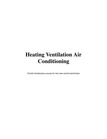
Screen Display617108713 14 1592534161181211191 The Meter selects the range with best resolution2 Direct current3 Negative reading4 Alternate current5 Low battery indicator6 Data hold7 Diode test8 Continuity test9 Relative zero mode10 Non-Contact Voltage11 Measurement units for Resistance12 Measurement units for Frequency13 Measurement units for Voltage14 Measurement units for Current15 Measurement units for Capacitance16 Auto Power Off17 Maximum / minimum reading memory18 Measurement unit for Temperature19 Analog bar graph display
AM-520 HVAC MultimeterAM-530 True-rms Electrical Contractor MultimeterCONTENTSSYMBOL.2SAFETY INFORMATION.2UNPACKING AND INSPECTION.3FEATURES.4MAKING MEASUREMENT.5Measuring AC and DC Voltage.6Measuring AC and DC Current.7Measuring Resistance.8Measuring Continuity.9Measuring Diode.9Measuring Capacitance.10Measuring Frequency.10Measuring Temperature C / F.11Non-Contact Voltage Sensing.12SPECIFICATION.13MAINTENANCE.16BATTERY AND FUSE REPLACEMENT.171
SYMBOLSX BFCaution! Risk of electric shock.TThe equipment is protected by double insulation or reinforcedinsulationJEarth (Ground)Caution! Refer to the explanation in this ManualAlternating Current (AC)Direct Current (DC)Audible toneBattery Complies with European DirectivesConforms to relevant Australian standards) Canadian Standards Association (NRTL/C)Do not dispose of this product as unsorted municipal waste.Contact a qualified recycler.'SAFETY INFORMATIONThe Meter complies with:IEC/EN 61010-1 3rd Edition, UL61010-1 2nd Ed. and CAN/CSA C22.2 No.61010.1-0.92 to Category III 600 Volts, Pollution degree 2IEC/EN 61010-2-030IEC/EN 61010-2-31 for test leadsEMC IEC/EN 61326-1Measurement Category III (CAT III) is for measurements performed in thebuilding installation. Examples are measurements on distribution boards,circuit- breakers, wiring, including cables, bus-bars, junction boxes, switches,socket-outlets in the fixed installation, and equipment for industrial useand some other equipment, for example, stationary motors with permanentconnection to the fixed installation.2
Measurement Category II (CAT II) is for measurements performed on circuitdirectly connected to low voltage installation. Examples are measurements onhousehold appliances, portable tools and similar equipments.X Warning: Read Before Using To avoid possible electrical shock or personal injury, follow theseinstructions and use the Meter only as specified in this manual. Do not use the Meter or test leads if they appear damaged, or if theMeter is not operating properly. If in doubt, have the Meter serviced. Always use the proper function and range for measurements. Before rotating the function range selection switch, disconnect testprobe from circuit under test. Verify the Meter’s operation by measuring on a known voltage source. Do not apply more than the rated voltage, as marked on the Meter,between the test probe or between any test probe and earth ground. Use the Meter with caution for voltages above 30 Vac rms, 42 Vac peak,or 60 Vdc. These voltages pose electrical shock hazards. Disconnect circuit power and discharge all high-voltage capacitors beforetesting resistance. Do not use the Meter around explosive gas or vapor. When using the test leads, keep your fingers behind the finger guards. Remove test leads from the Meter before opening the Meter case orbattery door.UNPACKING AND INSPECTIONYour shipping carton should include:1AM-520 or AM-5301Pair of test leads1Temperature probe1Velcro strap19V (6F22) battery (installed)1User manual1Carrying caseIf any of the items are damaged or missing, return the complete package tothe place of purchase for an exchange.3
FEATURESAM-520 is designed for HVAC applications with key functions such astemperature, micro amps used for flame sensor troubleshooting, as well asand capacitance to check the motor startup capacitors. The AM-520 measuresa complete range of electrical parameters and features a built in flashlight, a“third hand” probe holder and VoltTect non-contact voltage detection. Safetyrated to CAT III 600V.AM-530 is the fully-featured multimeter of choice for the professionalelectrical contractor. Measure and verify presence of voltage in order toconnect equipment or to perform repairs, run new wiring, check continuityof electrical connections, identify blown fuses, troubleshoot motors or checktransformers. The AM-530 features Truerms sensing to accurately measurevoltage on systems affected by harmonics, a built in flashlight to detect wirecolors in the dark, a “third hand” probe holder and non-contact voltagedetection. Safety rated to CAT III 600V. Measurements: Voltage up to 600VAC and 600VDC, AC/DC current,Resistance, Frequency, Capacitance, Temperature. Frequency, Capacitance, Duty Cycle for troubleshooting applications Special Functions:- Non-contact Voltage Detection- Audible continuity- Diode Test Backlit LCD display with analog bar graph Events:- Data hold- MAX / MIN Memory- Relative zero mode Built in work light (flashlight) Built in test leads storage and “third hand holder” Auto and Manual ranging Auto power off Low battery warning Velcro strap to hang a meter Safety: CAT III 600V4
MAKING MEASUREMENTX 1. Use the proper function and range for measurements.2. To avoid possible electrical shock, personal injury or damages to theMeter, disconnect circuit power and discharge all high-voltage capacitorsbefore testing resistance and diode.3. Connecting test leads: Connect the common (COM) test lead to the circuit before connectingthe live lead; After measurement, remove live lead before removing the common(COM) test lead from the circuit4. Symbol “OL” is displayed on LCD when the measurement is out of range.Rotary Switch PositionsSwitch PositionMeasurement FunctionAC or DC voltage measurement (use SELECT button forswitching to AC or DC).VResistance measurementeVoltage measurement of diode PN junctionGContinuity measurementμAECapacitance measurementHzFrequency measurement C FTemperature measurementNCVNon-contact voltagemAAAC or DC current measurement (use SELECT button forswitching to AC or DC).Function ButtonsButtonMeasurement FunctionSELECTSwitching AC or DC. Press the yellow SELECT button to selectalternate measurement functions on the rotary switch.HOLD /Display freezes present reading / press 2 sec to turn onLCD backlight.5
RELRelative zero modeRANGEManual or Auto range switching. The default settingis Auto ranging, press to switch to manual ranging(selectable resolutions). Press for 2 sec to return to autoranging.MAX/MINMaximum / minimum reading memory.Flash lightPressto enable the function when at relevant rotary switch function.Auto Power OFFAuto power off: approx. 15 minutes.When the Meter is in auto power off mode, press any button to resumenormal operation.Measuring AC and DC VoltagePress SELECT button to select AC/DC voltage measurement function.X To avoid personal injury or damage to the Meter, do not applyvoltage higher than 600Vac and 600Vdc.6
Measuring AC and DC CurrentPress SELECT button to select AC or DC current measurement function.X To avoid personal injury or damage to the Meter:1. Do not attempt to make an in-circuit current measurement when theopen-circuit potential to earth ground exceeding AC 600V or DC 600V2. Switch to proper function and range for your measurement.3. Do not place the test probe in parallel with a circuit when the test leadsare connected to the current terminals.4. Connect the test leads to the correct input A/mA μA current terminal andto the circuit before powering the circuit under test.5. For current range from 8-10A, do not measure current for more than 20minutes. Wait for 10 minutes before taking another measurement6. After measurement, switching OFF the circuit’s power before removingtest leads from the circuit.7
RLRLMeasuring ResistanceX Disconnect circuit power and discharge all high-voltage capacitorsbefore testing resistance.Note: On a higher resistance measurement ( 1Me), the measurement maytake a few seconds to get stable reading.Over range or open circuit indication: OL8
Measuring ContinuityX Disconnect circuit power and discharge all high-voltage capacitorsbefore testing continuity.Measuring DiodeX Disconnect circuit power and discharge all high-voltage capacitorsbefore testing diode.9
Measuring CapacitanceX Disconnect circuit power and discharge all high-voltage capacitorsbefore testing capacitance.Measuring FrequencyX To avoid personal injury or damage to the Meter, do not applyvoltage higher than 600V.10
Measuring Temperature C / FX 1. To avoid personal injury or damage to the Meter, do not applythetemperature probe to any live conductive parts.2. Temperature sensor K type (nickel-chromium/nichrosi) thermocouple issuitable for temperature measurement below 230 C (446 F).Measurement steps:Step 1: Turn the rotary switch to C or F position. The display will show “OL”.Step 2: Connect the temperature probe (K type) to the Meter and to thesurface to be measured.11
Non-Contact Voltage Sensing1. To avoid personal injury or damage to the Meter, do not test on uninsulated high voltage wires.2. Buzzer will sound and screen will display “OL” when sensing AC voltagebetween 90V and 600V3. Do not test on hazardous live wires higher than AC 600V4. Before and after hazardous voltage measurements, test the Meter byapproaching to a known source such as a line AC voltage or outlet todetermine proper operation. See below figure.Measuring distance8mmBuzzer will sound when the detected voltage is 90V, and the buzzer will beon.The distances between the wire and the meter should be 8mm.X At NCV mode, LCD will display OL. No test lead connection are required forNCV measurement.12
SPECIFICATIONAmbient temperature: 73.4 F 9 (23 C 5 C); Relative temperature: 75%Accuracy: (% of reading digits)Maximum voltage between input terminal and earth ground: AC 600Vrms orDC 600V Fuse for mA µA input: F1 fuse, 0.5A H 1000V fast-fuse, (6.3 32)mm Fuse for 10A input: F2 fuse, 11A H 1000V fast-fuse, (10 38)mmMaximum display: Digital 3999 counts, updates 3/sec. Frequency: 9999 counts.Analog pointer display: 41 segments, updates 30 times/sec.Over-range indication: OLRange: Automatic and ManualAltitude: Operating 2000mOperating temperature: 0 C 40 C (32 F 104 F)Relative humidity: 0 C 30 C (32 F 86 F) 75%; 30 C 40 C (86 F 104 F) 50%Storage temperature: -10 C 50 C (14 F 122 F)Electromagnetic compatibility: In an RF filed of 1V/m Specified accuracy 5%Battery: 9V, 6F22, NEDA1604 or equivalentLow battery indication:Dimensions (L x W x H): 182 mm x 90 mm x 45 mm (7.2 in x 3.5 in x 1.8 in)Weight: Approx. 354g (0.78lb) with batteries installed1. DC Voltage MeasurementRangeResolutionAccuracy400.0mV0.1mV (0.8% 3LSD)4.000V1mV40.00V10mV400.0V100mV600V1V (0.8% 1LSD) (1.0% 3LSD)Input impedance: About 10M ;(Input impedance is 3Ge except DC 400mV range)Overload protection: 600V13
2. AC Voltage MeasurementRangeResolutionAccuracy400.0mV0.1mV (1.2% 3LSD)4.000V1mV40.00V10mV400.0V100mV600V1V (1.0% 3LSD) (1.2% 3LSD)Note: Manual range only for 400.0mV range.Input impedance: Around 10MΩFrequency response: 45Hz 400HzAM-520 : Average sensing, rms indication.AM-530 : True RMS.Overload protection: 600Vrms3. Resistance MeasurementRangeResolutionAccuracy400.0Ω0.1Ω (1.2% 2LSD)4.000kΩ1Ω40.00kΩ10Ω400.0kΩ100Ω (1.0% 2LSD)4.000MΩ1kΩ (1.2% 2LSD)40.00MΩ10kΩ (1.5% 5LSD)400Ω range: Measured value (Measured display value – Short-circuitingvalue of probe)Open circuit voltage: Around 0.5VOverload protection: 600Vrms4.: Circuit ON/OFFRangeG : Diode measurementResolutionAccuracyOpen circuit voltage is around 0.5V.0.1ΩResistance 150Ω, buzzer will not sound.Resistance 10Ω, buzzer will sound.14
G1mVDisplay range is 0V to 2.0V. Normal voltage is around0.5V to 0.8V for silicon PN junction.Overload protection: 600V5. Capacitance MeasurementRangeResolutionAccuracy40.00nF10pF (3% 10LSD) under REL status400.0nF100pF4.000μF1nF (3% 5LSD) under REL status40.00μF10nF (3% 5LSD)400.0μF100nF (4% 5LSD)4000μF1μFFor reference onlyOverload protection: 600V6. Frequency MeasurementRangeResolutionAccuracy10Hz 10MHz0.01Hz 0. 01MHz (0.1% 4LSD)Overload protection: 600Vrms7. DC Current .00A10mA (1.0% 2LSD) (1.2% 3LSD)Overload protection:mA /μA range:F1 fuse, 0.5A H 1000V fast-fuse, ( 6.3 32)mm10 A range:F2 fuse, 11A H 1000V fast-fuse, ( 10 38)mm15
8. AC Current .00A10mA (1.2% 3LSD) (1.5% 3LSD)Frequency response: 45Hz 400HzAM-520 : Average sensing, rms indication.AM-530 : True RMS.Overload protection:mA /μA range:F1 fuse, 0.5A H 1000V fast-fuse, ( 6.3 32)mm10 A range:F2 fuse, 11A H 1000V fast-fuse, ( 10 38)mm9. Temperature MeasurementRange-40 – 0 C 0 – 100 C 100 – 1000 C-40 – 32 F 32 – 212 F 212 – 1832 FResolution0.1 C @ 400 C1 C @ 400 C0.1 F @ 752 F1 F @ 752 FAccuracy (10% 4 C) (1.2% 3 C) (2.5% 2 C) (20% 6 F) (1.8% 6 F) (2.5% 4 F)Overload protection: 600VK type (nickel-chromium/nichrosi) thermocouple must be used for temperaturemeasurement.16
MAINTENANCE AND REPAIRIf the Meter fails to operate, check battery, test leads, etc., and replace asnecessary.Double check the followings:1. Replace the fuse or battery if the meter does not work.2. Review the operating instructions for possible mistakes in operatingprocedure.Quick check on 0.5A FUSE:Step 1: Turn the rotary switch to Ω function.Step 2: short-circuit E/V/Ω/Hz terminal and mA/μA terminal.Resistance reading 1MΩ: the fuse is OKResistance reading “OL”: the fuse is open. Replace the fuse as specified.Quick check on 10A FUSE:Step 1: Turn the rotary switch to Ω function.Step 2: short-circuit E/V/Ω/Hz terminal and A terminal.Resistance reading 0.5Ω: the fuse is OK.Resistance reading “OL”: the fuse is open. Replace the fuse as specified.17
Except for the replacement of the battery, repair of the meter should beperformed only by a Factory Authorized Service Center or by other qualifiedinstrument service personnel.The front panel and case can be cleaned with a mild solution of detergent andwater. Apply sparingly with a soft cloth and allow to dry completely beforeusing. Do not use aromatic hydrocarbons, Gasoline or chlorinated solvents forcleaning.BATTERY AND FUSE REPLACEMENTX WARNINGTo avoid shock, injury, or damage to the Meter:Disconnect test leads before opening case.Use ONLY fuses with the amperage, interrupt, voltage, and speed ratingsspecified.Replacing BATTERY follow below steps:1. Disconnect the test lead probe from measuring circuit.2. Turn the Meter to OFF position.3. Remove the screws from the battery cover and open the battery cover4. Remove the batteries and replace with one 9V (6F22) or equivalent. Thebattery cover provides the correct polarity fitting construction design.Install the battery in the battery cover.5. Put the battery cover back and re-fasten the screw.Battery: 9V (6F22) Battery or equivalentReplacing FUSE follow below steps:1. Disconnect the test lead probe from measuring circuit.2. Turn the Meter to OFF position.3. Remove the screws from the enclosure and open the enclosure.4. Remove the broken fuse and replace with new specified fuse.5. Put the enclosure back and re-fasten the screw.Fuse ratings:mA /μA input terminal: F1 fuse, 0.5A H 1000V fast-fuse, ( 6.3 32)mm10 A input terminal: F2 fuse, 11A H 1000V fast-fuse, ( 10 38)mm18
9V batteryF1F219
AM-520Multimètre CVCAM-530Mode d’emploi10/2017, Rév.4 2017 Amprobe Test Tools.Tous droits réservés. Imprimé en Chine.FrançaisMultimètre d’électricien avec TRMS
Limites de garantie et de responsabilitéAmprobe garantit l’absence de vices de matériaux et de fabrication de ce produit pendantune période d’un an prenant effet à la date d’achat, sauf disposition contraire prévue parla loi. Cette garantie ne s’applique pas aux fusibles, aux piles jetables ni à tout produit malutilisé, modifié, contaminé, négligé ou endommagé par accident ou soumis à des conditionsanormales d’utilisation et de manipulation. Les revendeurs n’ont pas l’autorisation deprolonger toute autre garantie au nom d’Amprobe. Pour bénéficier de la garantie, renvoyezle produit accompagné d’un justificatif d’achat auprès d’un centre de services agréé parAmprobe ou d’un distributeur ou d’un revendeur Amprobe. Voir la section Réparation pourtous les détails. LA PRÉSENTE GARANTIE EST LE SEUL ET EXCLUSIF RECOURS DE L’UTILISATEURTOUTES AUTRES GARANTIES, EXPLICITES, IMPLICITES OU STATUTAIRES, NOTAMMENTLE CAS ÉCHÉANT LES GARANTIES DE QUALITÉ MARCHANDE OU D’ADAPTATION À UNOBJECTIF PARTICULIER SONT EXCLUES PAR LES PRÉSENTES. LE FABRICANT NE SERA ENAUCUN CAS TENU RESPONSABLE DE DOMMAGES PARTICULIERS, INDIRECTS, ACCIDENTELSOU CONSÉCUTIFS, NI D’AUCUNS DÉGATS OU PERTES DE DONNÉES, SUR UNE BASECONTRACTUELLE, EXTRA-CONTRACTUELLE OU AUTRE. Étant donné que certaines juridictionsn’admettent pas les limitations d’une condition de garantie implicite ou l’exclusion ou lalimitation de dégâts accidentels ou consécutifs, il se peut que les limitations et les exclusionsde cette garantie ne s’appliquent pas à votre cas.RéparationTous les outils de test renvoyés pour être réparés au titre de la garantie ou pour étalonnagedoivent être accompagnés des éléments suivants : nom, raison sociale, adresse, numéro detéléphone et justificatif d’achat. Ajoutez également une brève description du problème ou duservice demandé et incluez les cordons de test avec l’appareil. Les frais de remplacement oude réparation hors garantie doivent être acquittés par chèque, mandat, carte de crédit avecdate d’expiration, ou par bon de commande payable à l’ordre de Amprobe .Remplacements et réparations sous garantie – Tous paysVeuillez lire la déclaration de garantie et vérifiez la pile avant de demander une réparation.Pendant la période de garantie, tout outil de test défectueux peut être renvoyé auprès devotre distributeur Amprobe pour être échangé contre un produit identique ou similaire.Consultez la section « Where to Buy » sur le site amprobe.com pour obtenir la liste desdistributeurs dans votre région. Les appareils sous garantie devant être remplacés ou réparésau Canada et aux États-Unis peuvent également être envoyés dans un centre de servicesAmprobe (voir les adresses ci-dessous).Remplacements et réparations hors garantie – Canada et États-UnisLes appareils à réparer hors garantie au Canada et aux États-Unis doivent être envoyés dansun centre de services Amprobe . Appelez Amprobe ou renseignez-vous auprès de votre lieud’achat pour connaître les tarifs en vigueur de remplacement ou de réparation.Aux États-Uniset au CanadaAmprobeAmprobeEverett, WA 98203Mississauga, ON L4Z 1X9CanadaTél. : 877-AMPROBE (267-7623)Tél. : 905-890-7600Remplacements et réparations hors garantie – EuropeLes appareils européens non couverts par la garantie peuvent être remplacés par votredistributeur Amprobe pour une somme nominale. Consultez la section « Where to Buy » surle site beha-amprobe.com pour obtenir la liste des distributeurs dans votre région.Adresse postale européenne*Beha-Amprobe In den Engematten 1479286 Glottertal, AllemagneTél. : 49 (0) 7684 8009 - 0beha-amprobe.com*(Réservée à la correspondance – Aucun remplacement ou réparation n’est possible à cetteadresse. Nos clients européens doivent contacter leur distributeur.)
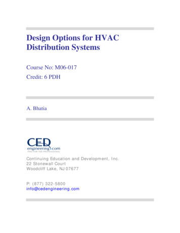
Multimètre CVC AM-520Multimètre d’électricien AM-530 avec TRMS123465107981 Lampe-torche4 Bouton de lampe-torche2 Afficheur LCD5 Sélecteur rotatif3 Boutons de fonction6 Bouton de sélection SELECT7 Borne d’entrée pour les mesures de tension, de capacité, derésistance, de température, et le contrôle de diode et de continuité8 Borne de retour COM pour toutes les mesures9 Borne d’entrée pour les mesures A ac/dc mA/uA10 Borne d’entrée pour les mesures A ac/dc jusqu’à 10 A
Affichage617108713 14 1592534161181211191 Le multimètre numérique sélectionne la gamme avec lameilleure résolution2 Mesure continue3 Lecture négative4 Mesure alternative5 Témoin de pile faible6 Maintien des données affichées7 Contrôle de diode8 Contrôle de continuité9 Mode du zéro relatif10 Tension sans contact11 Unités de mesure de la résistance12 Unités de mesure de la fréquence13 Unités de mesure de la tension14 Unités de mesure du courant15 Unités de mesure de la capacité16 Mise en veille automatique17 Mémoire de lecture maximum / minimum18 Unités de mesure des températures19 Graphique à barres analogique
Multimètre CVC AM-520Multimètre d’électricien AM-530 avec TRMSTABLE DES MATIÈRESSYMBOLES.2CONSIGNES DE SÉCURITÉ.2DÉBALLAGE ET INSPECTION.3FONCTIONNALITÉS.4OPÉRATIONS DE MESURE.5Mesure de tension alternative et continue.6Mesure de courant alternatif et continu.7Mesure de résistance.8Contrôle de continuité.9Contrôle de diode.9Mesure de capacité.10Mesure de fréquence.10Mesure de température C / F.11Détection de tension sans MENT DES FUSIBLES ET DES PILES.181
SYMBOLES Attention ! Risque de décharge électriqueAttention ! Se reporter aux explications de ce manuelMesure alternative (ac)Mesure continue (dc)L’équipement est protégé par une double isolation ou une isolationrenforcéePrise de terreSignal sonoreBatterie Conforme aux directives européennesConforme aux directives de l’association australienne denormalisation) Association canadienne de normalisation (CSA)Ne pas mettre ce produit au rebut parmi les déchets ménagers.Consulter un centre de recyclage homologué.CONSIGNES DE SÉCURITÉLe multimètre numérique est conforme à ;CEI/EN 61010-1 3e édition, UL61010-1 2e éd. et CAN/CSA C22.2 nº 61010.1-0.92jusqu’à la catégorie III 600 V, degré de pollution 2CEI/EN 61010-2-030CEI/EN 61010-2-31 pour les cordons de testCEM CEI/EN 61326-1La catégorie III (CAT III) de mesures concerne les mesures effectuées surles installations dans les bâtiments. Il s’agit, par exemple, des tableaux dedérivation, des coupe-circuit, du câblage, y compris les conducteurs, les barresomnibus, les boîtes de jonction, les commutateurs, les prises murales del’installation fixe, et le matériel destiné à l’utilisation industrielle, ainsi quecertains autres équipements tels que, par exemple, les moteurs fixes connectésen permanence à l’installation fixe.2
La catégorie II (CAT II) de mesures concerne les mesures effectuées sur lescircuits directement connectés à l’installation en basse tension. Il s’agit, parexemple, des mesures effectuées sur les appareils ménagers, les outils portatifset les appareils similaires.X Avertissement : À lire avant l’emploi Pour éviter les chocs électriques ou les risques de blessures, appliquer cesconsignes et utiliser uniquement le multimètre numérique en respectantles instructions de ce manuel. Ne pas utiliser le multimètre ou les cordons de test s’il
AM-520 is designed for HVAC applications with key functions such as temperature, micro amps used for flame sensor troubleshooting, as well as and capacitance to check the motor startup capacitors. The AM-520 measures a complete range of electrical parameters and features a built in flashlight, a