Transcription
HVAC Economizers 101Section #6MManufacturerf tSSpecificifi RTUEconomizer Controls6-1
Section #6-Manufacturer Specific RTUEconomizer Controls Trane Voyager Carrier Durablade & Centurian York equipment Lennox “LGC”LGC and“T” Model RTU6-2
Trane Voyager / Economizerp– Down FlowFeatures and Operations The down flow assembly includes fully modulating 0-100%motor and dampers, barometric relief, minimum positionsetting, preset linkage, fixed drybulb and spring returnactuator. The barometric relief damper shall be standard with the downflow economizer and shall provide a pressure operateddamper that shall be closed during the “off” cycle. Solid stateenthalpy and differential enthalpy controls are field-installedfield-installed.6-3
Trane Voyager / EconomizerpFeatures and Operations-Horizontal The horizontal economizer contains the same features asthe down flow economizer with the exception of barometricrelief. Motorized outside air dampers manually set outdoor airdampers and provide up to 50% outside airair. Once setset,outdoor air dampers shall open to set position when indoorfan starts. The damper shall close to the full closedposition when indoor fan shuts downdown.6-4
Trane Voyager Packaged RTU withEconomizer Control Actuator (ECA) The standard control equipment in the Voyager is a economizercontrol (ECA),(ECA) which is a microelectronic control system (Seecontroller on next page). The unit comes with a fixed drybulb changeover control with twooptional controlscontrols, enthalpy and differential enthalpy controlcontrol. The ECA monitors and controls the mixed air temperature, returnair temperature, minimum position set point (local or remote),power exhaustht sett point,i t CO2, andd ambientbi t drybulb/enthalpyd b lb/ th l sensoror comparative humidity (return air humidity against ambienthumidity) sensors, if selected. The economizer actuator is spring returned to the closed positionany time power is lost to the unit, and is powered by 24vac. Economizer operationpand status conditions are determined viaLED status light (more information provided later in presentation.)6-5
Trane Voyager with Economizer ControlEconomizer Control Start-Up Procedures Using the Service Test Guide in Table 7, (see next slide)momentarily jump across the Test 1 & Test 2 terminals on LTB1one time to start the minimum ventilation test (see next slide forjumper clarification). Each time the jumper touches the terminals,the controller will cycle to the next function.1. Set the minimum position set point for the economizer to therequired percentage of minimum ventilation using the remoteset point potentiometer located on the economizer control(ECA). The economizer will drive to its minimum position setpoint; fans will start when the SERVICE TEST is initiatedinitiated.2. Verify that the dampers stroked to the minimum position byvisually opening up the unit and physically looking at thedampers Note: The only way to determine the true minimumdampers.percentage control point is by calculating the percentage ofOSA using the formula discussed later in this presentation.3 To stop the SERVICE TEST3.TEST, turn the main power disconnectswitch to the “Off” position or proceed to the next componentstart-up procedure.6-6
Trane Voyager Easy Accessg Terminal Board (LTB)()Low Voltage Voyager’s low voltage terminal board (LTB) isexternal to the electrical control cabinetcabinet. It isextremely easy to locate and attach a temporaryjumper wire to test operation of the economizer andall unit functions.6-7
Trane Voyager with EconomizerControl - Test Guide6-8
Trane ECA EconomizerControl Module and Accessories6-9
Voyager ReliaTel ControlUnit Economizer Control (ECA)TroubleshootingVerify Economizer Status of Economizer Actuator (ECA) by LED indicator: OFF: No power or failure ON:ON NNormal,l OK tto economizei Slow Flash: Normal, not OK to economize Fast Flash - ¼ second On / 2 seconds off:– Error Code: Communications failure Pulse Flash: 1/30 second On / ¼ second off: (2 seconds between pulse sequences)Error Code: 1 Flash: Actuator fault 2 FlFlashes:hCO2 sensor 3 Flashes: RA humidity sensor 4 Flashes: RA temperature sensor 5 Flashes: OA quality sensor 6 Flashes: OA humidity sensor 7 Flashes: OA temperature sensor 8 Flashes: MA temperature sensor 9 Flashes: RAM fault 10 Flashes: ROM fault 11 Flashes: EEPROM fault6-10
Trane VoyagerProcedure to Verify System Operation Outside air damper is at minimum position when thesupplypp y fan is enabled. Note: This is an non-integratedgeconomizer control system. The outside air damper opens completely and thereturn damper closes completely during economizermode. Outside air damper is at minimum position when thecompressor isi enabled.bl d Outside air damper is at minimum position whenheating is enabledenabled. Verify mixed/discharge cut-out sensor wire isterminated on the SA terminal on the OEM board. Ifth sensor wirethei isi nott landedl d d on ththe SA tterminal,i l ththeeconomizer will not operate properly.6-11
Carrier Durablade Enthalpy control typically utilizes acustomized Honeywell controller.Checkout procedures are similar toHHoneywellll guidelinesid li For a drybulb thermostat– Generate call for cooling– Jumper across outside airthermostat– Verify outside air damper opensfully Disconnect outside air thermostatfrom circuit– Verify outside air damper closesand goes to minimum set point6-12
Troubleshooting Carrier RTU ControlsUtilizing the SchematicsActuatorSensorsController6-13
Troubleshooting Carrier 48HG RTUControls Utilizing the Schematics6-14
Troubleshooting Carrier 48HG RTUControls Utilizing the SchematicsControlBoardActuatorSensors6-15
Troubleshooting Carrier 50PG RTUControls Utilizing the SchematicsControllerActuatorSensors6-16
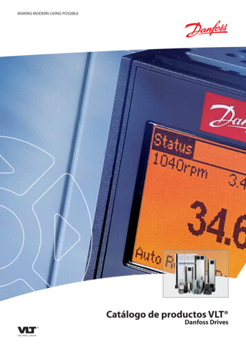
Troubleshooting Carrier 50PG RTUTesting the Actuator MotorSource: Carrier6-17
Troubleshooting Carrier 50PG RTUControls Utilizing the SchematicsEconoMi er IV Troubleshooting ECONOMI ER IV PREPARATION — This procedure is used to preparethe EconoMi er IV for troubleshooting. No troubleshooting or testing isdone by performing the following procedure.OThiss procedurep ocedu e requiresequ es a 99-V babattery,e y, 1.2 kilo-ohmooresistor,es s o , aandda NOTE:5.6 kilo-ohm resistor, which are not supplied with the EconoMi er IV.Troubleshooting Steps Disconnect power at TR and TR1. All LEDs should be off. Exhaust fancontacts should be open. NNotice:tiFFollowllththe HHoneywellll W7459 RReferencefGGuideid ffor remainingi isteps. Carrier Model 50PG comes equipped with Honeywell economizercontrols.6-18
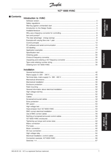
York Predator RTUEconomizer Schematic6-19
York-Predator RTU Economizer Sectionon SchematicSensorsController andActuator6-20
Lennox LGC RTU’s with Economizers6-21
Lennox LGC Series RTU Economizersare Powered byy 24 Vac at TB346-22
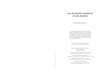
Lennox LGC Series RTU EconomizersSEQUENCE OF OPERATION, L" SERIES ECONOMIZER((See Next Slide for Associated Schematic))POWER:11.Terminal strip TB34 energizes the economizer components with 24 VacVac.OPERATION:2.The main control module A55 along with outdoor enthalpy sensor A7 andindoor enthalpy sensor A62 (if differential enthalpy is used) communicates tothe economizer control module A56 when to power the damper motor B7.3.The economizer control module A56 supplies B7 with between 0 and 10 Vdc tocontrol the positioning of economizer.4.The damper actuator provides 2 to 10 Vdc position feedback.5.The economizer control module A56 receives a demand and energizes exhaustfan relay K65 with 24 Vac at 50% (travel) outside air damper open (adjustable).6.N.O. K65-1 and K65-2 both close, energizing exhaust fan motors B10 and B11.6-23
Troubleshooting the Lennox LGCSeries RTU Economizer SchematicSource: Lennox6-24
Testing the Lennox LGC Series RTU’sEconomizer SchematicSource: Lennox6-25
Lennox Economizer Logic6-26
Testing the Lennox “T” Series RTUEconomizerLennox “T” Series Economizer6-27
Lennox “T” Series Economizer6-28
Exercise #6((Provide Answers below on notes ppage)g )1. On the Trane model #WSC060E, with economizerControl,, what terminals are jumperedj pto start theeconomizer test?2. On the Carrier 50PG RTU, what terminals are tested toverify a signal to the OSA actuator?3. When testing the outside air temp sensor on the YorkPredator RTU, what terminals are used?4. On the Lennox L Series RTU, what is the signal thatgoes to the OSA damper motor?5. When troubleshooting any rooftop unit, what is one of thefirst steps a tech should practice prior to touching anypiece of the equipment?6-29
HVAC Economizers 101 Section #6 U T R i Mftf SiM anufacturer Specific RTU Economizer Controls 6-1. Section #6-Manufacturer Specific RTU Economizer Controls . When troubleshooting any rooftop unit, what is one of the first steps a tech should practice prior to touching any piece of the equipment? 6-29.