Transcription
User andService GuidePublication number 54600-97021November 1997 (pdf version Nov 1998)For Safety Information, Warranties, and Regulatory information,see the pages behind the index. Copyright Hewlett-Packard Company 1992, 1997All Rights ReservedHP 54600B, HP54601B,HP 54602B, and HP 54603BOscilloscopes
General-Purpose OscilloscopesThe HP 54600B-Series Oscilloscopes offer exceptional waveformviewing and measurements in a small, lightweight package. Thetwo-channel HP 54600B and HP 54603B are suited for production,field service, and education applications. The four-channelHP 54601B is best suited for research and design labs, andapplications involving digital circuit test and troubleshooting. Forhigher frequency applications, the HP 54602B provides 150 MHzbandwidth and triggering up to 250 MHz. Each of these oscilloscopesgives you: 60-MHz bandwidth (HP 54603B)100-MHz bandwidth (HP 54600B and HP 54601B)150-MHz bandwidth (HP 54602B) Automatic setup of the front panelAutomatic and cursor measurements of frequency, time, and voltageWaveform storageSave and recall of 16 front-panel setupsPeak detectThese oscilloscopes are easy to use with familiar controls and highdisplay update rate, but with none of the viewing problems that areassociated with analog oscilloscopes. A bright, crisp display isobtained at all sweep speeds and delayed sweep magnifications.Storage is as simple as pressing a button. Negative time allows theviewing of events that occur before the trigger event. Cursors andautomatic measurements greatly simplify the analysis of these events.You can upgrade this oscilloscope for hardcopy or remote control withthe addition of an interface module. Unattended waveformmonitoring and additional waveform math, such as FFT, can be addedwith the addition of one of the Measurement/Storage modules.ii
Bring your scope and PC together with BenchLink software.BenchLink, which runs under Windows, allows easy transfer of scopetraces and waveform data to your PC for incorporation intodocuments or storage.Accessories supplied Two 1.5 meter, 10:1 Probes (HP 10071A)Power cord for country of destinationThis User and Service GuideProgrammer’s Guide with Microsoft Windows Help file, ascii helpfile, and sample programs.Accessories available HP 34810B BenchLink/Scope Software for WindowsHP 54650A HP-IB Interface ModuleHP 54652A Parallel Interface ModuleHP 54654A Operator’s Training KitHP 54655A and HP 54656A Test Automation ModulesHP 54657A HP-IB Measurement Storage ModuleHP 54659B Serial/Parallel Measurement/Storage ModulesHP 5041-9409 Carrying CaseHP 5062-7345 Rackmount KitHP 10070A 1.5 meter, 1:1 ProbeHP 10100C 50 Ω Terminationiii
Options available Option 001 RS-03 Magnetic Interference Shielding Added to CRT Option 103 Operator’s Training Kit (HP 54654A)ivOption 002 RE-02 Display Shield Added to CRTOption 005 Enhanced TV/Video Trigger (HP 54602B only)Option 090 Deletes ProbesOption 101 Accessory Pouch and Front-Panel CoverOption 102 Two Additional HP 10071A 10:1 Probes (HP 54602Bonly)Option 104 Carrying Case (HP 5041-9409)Option 106 BenchLink/Scope Software (HP 34810B)Option 1CM Rackmount Kit (HP 5062-7345)Power Cords (see the table of Replaceable Parts at the end ofChapter 4, Service.)
In This BookThis manual is the user and serviceguide for the HP 54600B, HP 54601B,HP 54602B, and HP 54603BOscilloscopes, and contains fivechapters.First Time Users Chapter 1 is a quickstart guide that gives you a brief overviewof the oscilloscope.Advanced users Chapter 2 is a series ofexercises that guide you through theoperation of the oscilloscope.1The Oscilloscope at a Glance2Operating Your Oscilloscope3Using Option 005 EnhancedTV/Video Trigger (HP 54602B)4Service5Performance CharacteristicsGlossaryIndexTV/Video triggering Chapter 3 showshow to use enhanced TV/Video triggeringif you have Option 005 installed in youroscilloscope.Service technicians Chapter 4contains the service information for theoscilloscope. There are procedures forverifying performance, adjusting,troubleshooting, and replacing assembliesin the oscilloscope.Reference information Chapter 5 liststhe characteristics of the oscilloscope.v
vi
Contents1 The Oscilloscope at a GlanceTo inspect the instrument 1–6To clean the instrument 1–6To connect a signal to the oscilloscopeTo display a signal automatically 1–9To set up the vertical window 1–10To set up the time base 1–12To trigger the oscilloscope1–14To use roll mode 1–161–72 Operating Your OscilloscopeTo use delayed sweep 2–3To use storage oscilloscope operation 2–6To capture a single event 2–8To capture glitches or narrow pulses 2–10To trigger on a complex waveform 2–12To make frequency measurements automatically 2–14To make time measurements automatically 2–16To make voltage measurements automatically 2–19To make cursor measurements2–22To view asynchronous noise on a signal 2–26To reduce the random noise on a signal 2–28To save or recall traces 2–31To save or recall front-panel setups 2–32To reset the instrument setup 2–33To use the XY display mode 2–34To analyze video waveforms 2–38Contents–1
Contents3 Using Option 005 Enhanced TV/Video Trigger (HP 54602B)To select TV display grid 3–4To autoscale on a video signal 3–4To trigger on a specific line of video 3–5To trigger on all TV line sync pulses 3–7To trigger on a specific field of the video signal 3–8To trigger on all fields of the video signal 3–9To trigger on odd or even fields 3–10To make cursor measurements 3–12To use delayed sweep 3–14To analyze video waveforms with Option 005 3–16To window in on harmonic distortion using FFT 3–18To connect to other instruments 3–204 ServiceTo return the oscilloscope to Hewlett-PackardVerifying Oscilloscope Performance4–44–5To check the output of the DC CALIBRATOR4–6To verify voltage measurement accuracy4–7To verify bandwidth4–10To verify bandwidth (alternate method) 4–12To verify horizontal t and 1/ t accuracy4–16To verify trigger sensitivity4–18To verify Vertical Output on Option 005 4-22Contents–2
ContentsAdjusting the Oscilloscope4–27To adjust the power supply 4–28To perform the self-calibration4–31To adjust the low-frequency compensation 4–33To adjust the high-frequency pulse response 4–35To adjust the display 4–37To adjust the Option 005 offset (R15) (HP 54602B only)Troubleshooting the Oscilloscope4–394–40To construct your own dummy load4–41To check out the oscilloscope4–42To check the Low Voltage Power Supply4–45To run the internal self-tests4–464–48To troubleshoot Option 005 (HP 54602B only)Replacing Parts in the Oscilloscope4–49To replace an assembly 4–50To remove the fan 4–51To remove the front panel 4–51To remove the display 4–53To remove the system board 4–53Power supply 4–54Keyboard 4–55To remove the handle 4–56To remove the Option 005 board 4–56To order a replacement part 4–57Contents–3
Contents5 Performance CharacteristicsVertical System 5–3Horizontal System 5–5Trigger System 5–6XY Operation 5–8Display System 5–8Acquisition System 5–9Advanced Functions 5–10Power Requirements 5–10General 5–11Option 005 General Performance Characteristics (HP 54602B only)Option 005 Trigger System (HP 54602B only) 5–14GlossaryIndexContents–45–13
1The Oscilloscope at a Glance
The Oscilloscope at a GlanceOne of the first things you will want to do with your new oscilloscopeis to become acquainted with its front panel. Therefore, we havewritten the exercises in this chapter to familiarize you with some of itscontrols.The front panel has knobs, grey keys, and white keys. The knobs areused most often and are similar to the knobs on other oscilloscopes.The grey keys bring up softkey menus on the display that allow youaccess to many of the oscilloscope features. The white keys areinstant action keys and menus are not associated with them.Throughout this book, the front-panel keys are denoted by a boxaround the name of the key, and softkeys are denoted by a change inthe text type. For example, Source is the grey front-panel keylabeled source under the trigger portion of the front panel, andLine is a softkey. The word Line is at the bottom of the displaydirectly above an unlabeled softkey (which is also grey).1–2
The Oscilloscope at a GlanceFigure 1-1 is a diagram of the front-panel controls and inputconnectors of the HP 54600B and HP 54603B. Figure 1-2 is a diagramof the front-panel controls and input connectors of the HP 54601Band HP 54602B.Figure 1-3 is a status line example on the HP 54602B. The status line,located at the top of of the display, lets you quickly determine thesetup of the oscilloscope. In this chapter you will learn to read at aglance the setup of the oscilloscope from the status line.Figure 1-4 is a diagram showing which grey keys to press to bring upthe various softkey menus.Figure nelcontrolsExternaltrigger inputChannelinputsHorizontalcontrolsHP 54600B and HP 54603B Front Panel Controls1–3
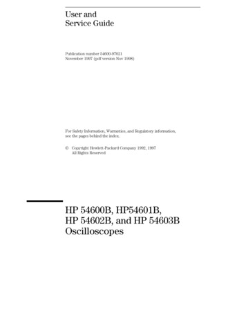
Figure riggercontrolsChannelcontrolsChannelinputsHP 54601B and HP 54602B Front Panel ControlsFigure 1–3Channel 4 is on, 10 V/divDelayed sweep is on, 500 ns/divMain sweep 500 µs/divAutostore is onChannel 3 is offChannel 2 is on, 4 V/divChannel 1 is on, ac coupled, inverted, 100 mV/divHP 54602B Display Status Line Indicators1–4Auto triggered, positiveslope; trigger source ischannel 1Peak detect is on and operating
Figure 1–4Press this keyTo obtain this menuPress this keyTo obtain this menuSoftkey Menu Reference1–5
The Oscilloscope at a GlanceTo inspect the instrumentTo inspect the instrumentInspect the shipping container for damage.Keep a damaged shipping container or cushioning material until the contentsof the shipment have been checked for completeness and the instrument hasbeen checked mechanically and electrically.Check the accessories.Accessories supplied with the instrument are listed in "Accessories Supplied"in the front of this manual. If the contents are incomplete or damaged notify your HP sales office.Inspect the instrument. If there is mechanical damage or defect, or if the instrument does notoperate properly or pass performance tests, notify your HP sales office. If the shipping container is damaged, or the cushioning materials showsigns of stress, notify the carrier as well as your HP sales office. Keep theshipping materials for the carrier’s inspection. The HP office will arrangefor repair or replacement at Hewlett-Packard’s option without waiting forclaim settlement.To clean the instrumentIf this instrument requires cleaning, disconnect it from all power sources andclean it with a mild detergent and water. Make sure the instrument iscompletely dry before reconnecting it to a power source.1–6
The Oscilloscope at a GlanceTo connect a signal to the oscilloscopeTo connect a signal to the oscilloscopeThe HP 54600B and HP 54603B are a two-channel oscilloscopes with anexternal trigger input, while the HP 54601B and HP 54602B are four-channeloscilloscopes. The four-channel oscilloscope replaces the external triggerinput with channels 3 and 4. In this exercise you connect a signal to thechannel 1 input.To avoid damage to your new oscilloscope, make sure that the voltage level ofthe signal you are using is less than or equal to 400 V (dc plus the peak ac).For a complete list of the characteristics see chapter 5, "PerformanceCharacteristics." Use a cable or a probe to connect a signal to channel 1.If you are using a probe, the oscilloscope allows you to enter the attenuationfactor for the probe. The attenuation factor changes the vertical scaling ofthe oscilloscope so that the measurement results reflect the actual voltagelevels at the probe tip. To set the probe attenuation factor press1 . Next toggle the Probesoftkey to change the attenuation factor to match the probe you areusing.1–7
The Oscilloscope at a GlanceTo connect a signal to the oscilloscopeYou should compensate 10:1 probes to match their characteristics to theoscilloscope. A poorly compensated probe can introduce measurementerrors. To compensate a probe, follow these steps.1 Connect the 10:1 probe from channel 1 to the front-panel probe adjustsignal on the oscilloscope.2 Press Autoscale .3 Use a nonmetallic tool to adjust the trimmer capacitor on the probefor the flattest pulse possible as displayed on the oscilloscope.Figure 1–5Overcompensationcauses pulse peaking.Figure 1–6Correct compensationwith a flat pulse top.Figure 1–7Undercompensationcauses pulse rolloff.1–8
The Oscilloscope at a GlanceTo display a signal automaticallyTo display a signal automaticallyThe oscilloscope has an Autoscale feature that automatically sets up theoscilloscope to best display the input signal. Using Autoscale requires signalswith a frequency greater than or equal to 50 Hz and a duty cycle greater than1%.When you press the Autoscale key, the oscilloscope turns on and scales allchannels that have signals applied, and it selects a time base range based onthe trigger source. The trigger source selected is the highest numbered inputthat has a signal applied. (If a signal is connected to the external triggerinput on the HP 54600B and HP 54603B, then it is selected as the triggersource.)1 Connect a signal to the oscilloscope.2 Press Autoscale .When you press the Autoscale key, the oscilloscope changes the front-panelsetup to display the signal. However, if you pressed the Autoscale keyunintentionally, you can use the Undo Autoscale feature. To use this feature,perform the following step. PressSetup. Next, press the Undo Autoscale softkey.The oscilloscope returns to the configuration in effect before youpressed the Autoscale key.1–9
The Oscilloscope at a GlanceTo set up the vertical windowTo set up the vertical windowThe following exercise guides you through the vertical keys, knobs, andstatus line.1 Center the signal on the display with the Position knob.The Position knob moves the signal vertically, and it is calibrated. Noticethat as you turn the Position knob, a voltage value is displayed for a shorttime indicating how far the ground reference is located from the center of thescreen. Also notice that the ground symbol on the right side of the displaymoves in conjunction with the Position knob.Measurement hintsIf the channel is dc coupled, you can quickly measure the dc component of thesignal by simply noting its distance from the ground symbol.If the channel is ac coupled, the dc component of the signal is removed allowingyou to use greater sensitivity to display the ac component of the signal.1–10
The Oscilloscope at a GlanceTo set up the vertical window2 Change the vertical setup and notice that each change affects thestatus line differently.You can quickly determine the vertical setup from the status line in thedisplay. Change the vertical sensitivity with the Volts/Div knob and notice that itcauses the status line to change. For channels 3 and 4 on the HP 54601Band HP 54602B, press 3 or 4 . Then use the softkeys to changethe vertical sensitivity. Press1.A softkey menu appears on the display, and the channel turns on (orremains on if it was already turned on). Toggle each of the softkeys and notice which keys cause the status line tochange.Channels 1 and 2 have a vernier softkey that allows the Volt/Div knobto change the vertical step size in smaller increments. These smallerincrements are calibrated, which results in accurate measurementseven with the vernier turned on. To turn the channel off, either press1a second time or press theleft-most softkey.Invert operating hintWhen you are triggered on the signal you are inverting, the inversion alsoapplies to the trigger signal (what was a rising edge now is a falling edge). If thesignal has a 50% duty cycle (square wave or sine wave), the displayedwaveform appears not to invert. However, for signals with a duty cycle otherthan 50%, the displayed waveform does invert as you would expect.1–11
The Oscilloscope at a GlanceTo set up the time baseTo set up the time baseThe following exercise guides you through the time base keys, knobs, andstatus line.1 Turn the Time/Div knob and notice the change it makes to the statusline.The Time/Div knob changes the sweep speed from 2 ns to 5 s in a 1-2-5 stepsequence, and the value is displayed in the status line.2 Change the horizontal setup and notice that each change affects thestatus line differently. PressMain/Delayed.A softkey menu appears on the display with six softkey choices. Toggle each of the softkeys and notice which keys cause the status line tochange.There is also a horizontal vernier softkey that allows the Time/Divknob to change the sweep speed in smaller increments. These smallerincrements are calibrated, which results in accurate measurementseven with the vernier turned on.1–12
The Oscilloscope at a GlanceTo set up the time base Turn the Delay knob and notice that its value is displayed in the status line.The Delay knob moves the main sweep horizontally, and it pauses at0.00 s, mimicking a mechanical detent. At the top of the graticule is asolid triangle ( ) symbol and an open triangle( ) symbol. The symbol indicates the trigger point and it movesin conjunction with the Delay knob. The symbol indicates the timereference point. If the time reference softkey is set to left, the islocated one graticule in from the left side of the display. If the timereference softkey is set to center, the is located at the center of thedisplay. The delay number tells you how far the reference point islocated from the trigger point .All events displayed left of the trigger point happened before thetrigger occurred, and these events are called pretrigger information.You will find this feature very useful because you can now see theevents that led up to the trigger point. Everything to the right of thetrigger point is called posttrigger information. The amount of delayrange (pretrigger and posttrigger information) available is dependenton the sweep speed selected. See "Horizontal System" in chapter 5 formore details.1–13
The Oscilloscope at a GlanceTo trigger the oscilloscopeTo trigger the oscilloscopeThe following exercise guides you through the trigger keys, knobs, and statusline.1 Turn the trigger Level knob and notice the changes it makes to thedisplay.On the HP 54601B and HP 54602B and on an internally triggered HP 54600Band HP 54603B, as you turn the Level knob or press a trigger menu key, for ashort time two things happen on the display. First, the trigger level isdisplayed in inverse video. If the trigger is dc coupled, it is displayed as avoltage. If the trigger is ac coupled or if LF reject was selected, it is displayedas a percentage of the trigger range. Second, if the trigger source is turnedon, a line is displayed showing the location of the trigger level (as long as accoupling or low frequency reject are not selected).2 Change the trigger setup and notice that each change affects thestatus line differently. PressSource.A softkey menu appears on the display showing the trigger sourcechoices. Toggle each of the softkeys and notice that each key causes the status lineto change. PressMode.A softkey menu appears on the display with five trigger mode choices. Toggle the Single and TV softkeys and notice that they affect the statusline differently. (You can only select TV if the trigger source is eitherchannel 1 or 2.)When the oscilloscope is triggering properly, the trigger mode portionof the status line is blank.1–14
The Oscilloscope at a GlanceTo trigger the oscilloscopeWhat happens if the oscilloscope loses trigger?If Auto Level is the trigger mode, Auto flashes in the status line. If dc coupled,the oscilloscope resets the trigger level to the center of the signal. If accoupled, the oscilloscope resets the trigger level to the middle of the screen.(Every time you press the Auto Level softkey, the oscilloscope resets the triggerlevel.)If Auto is the trigger mode, Auto flashes in the status line and the oscilloscopefree runs.If either Normal or TV is the trigger mode, the trigger setup flashes in the statusline. PressSlope/Coupling.A softkey menu appears on the display. If you selected Auto level,Auto, Normal, or Single as a trigger mode, six softkey choices aredisplayed. If you selected TV as a trigger source, five other softkeychoices are available. Toggle each of the softkeys and notice which keys affect the status line.On the HP 54600B and HP 54603B, external trigger is always dccoupled. If you select ac coupling or low frequency reject, thesefunctions do not occur until you change the trigger source to channel1, channel 2, or line.3 Adjust the Holdoff knob and notice the change it makes to thedisplay.Holdoff keeps the trigger from rearming for an amount of time that you setwith the Holdoff knob. Holdoff is often used to stabilize the complexwaveforms. The Holdoff range is from 200.0 ns to about 13.5 s. It isdisplayed, for a short time, in inverse video near the bottom of the display.1–15
The Oscilloscope at a GlanceTo use roll modeTo use roll modeRoll mode continuously moves data across the display from right to left. Itallows you to see dynamic changes (like adjusting a potentiometer) on lowfrequency signals. Two frequently used applications are transducermonitoring and power supply testing.1 Press Mode . Then press the Auto Lvl, Auto, or Normal softkey.2 Press Main/Delayed .3 Press the Roll softkey.The oscilloscope is now untriggered and runs continuously. Also notice thatthe time reference softkey selection changes to center and right.4 Press Mode . Then press the Single softkey.19orof the display (depending on the time210reference selection), then it searches for a trigger. After a trigger is found,the remainder of the display is filled. Then, the oscilloscope stops acquiringdata.You can also make automatic measurements in the roll mode. Notice that theoscilloscope briefly interrupts the moving data while it makes themeasurement. The acquisition system does not miss any data during themeasurement. The slight shift in the display after the measurement iscomplete is that of the display catching up to the acquisition system.The oscilloscope fills eitherRoll mode operating hints Roll mode operates on channels 1 and 2 only.Math functions, averaging, and peak detect are not available.Holdoff and horizontal delay do not affect the signal.Both a free running (nontriggered) display and a triggered display (availablein the single mode only) are available. Roll mode is available at sweep speeds up to 200 ms.1–16
2Operating Your Oscilloscope
Operating Your OscilloscopeBy now you are familiar with the VERTICAL, HORIZONTAL, and TRIGGERgroups of the front-panel keys. You should also know how todetermine the setup of the oscilloscope by looking at the status line.If you are unfamiliar with this information, we recommend you readchapter 1, "The Oscilloscope at a Glance."This chapter takes you through two new groups of front-panel keys:STORAGE, and the group of keys that contains the Measure,Save/Recall, and Display keys. You will also add to your knowledge ofthe HORIZONTAL keys by using delayed sweep.We recommend you perform all of the following exercises so youbecome familiar with the powerful measurement capabilities of theoscilloscope.2–2
Operating Your OscilloscopeTo use delayed sweepTo use delayed sweepDelayed sweep is a magnified portion of the main sweep. You can usedelayed sweep to locate and horizontally expand part of the main sweep for amore detailed (high resolution) analysis of signals. The following steps showyou how to use delayed sweep. Notice that the steps are very similar tooperating the delayed sweep in analog oscilloscopes.1 Connect a signal to the oscilloscope and obtain a stable display.2 Press Main/Delayed .3 Press the Delayed softkey.The screen divides in half. The top half displays the main sweep, and thebottom half displays an expanded portion of the main sweep. This expandedportion of the main sweep is called the delayed sweep. The top half also hastwo solid vertical lines called markers. These markers show what portion ofthe main sweep is expanded in the lower half. The size and position of thedelayed sweep are controlled by the Time/Div and Delay knobs. TheTime/Div next to thesymbol is the delayed sweep sec/div. The delayvalue is displayed for a short time at the bottom of the display. To display the delay value of the delayed time base, eitherpressMain/Delayedor turn the Delay knob. To change the main sweep Time/Div, you must turn off the delayed sweep.2–3
Operating Your OscilloscopeTo use delayed sweepSince both the main and delayed sweeps are displayed, there are half asmany vertical divisions so the vertical scaling is doubled. Notice the changesin the status line. To display the delay time of the delayed sweep, either pressMain/Delayed or turn the delay knob. The delay value isdisplayed near the bottom of the display.4 Set the time reference to either left or center.Figure 2-1 shows the time reference set to left. The operation is like thedelayed sweep of an analog oscilloscope, where the delay time defines thestart of the delayed sweep.Figure 2–1Delayed sweepmarkersTime reference set to left2–4
Operating Your OscilloscopeTo use delayed sweepFigure 2-2 shows the time reference set to center. Notice that the markersexpand around the area of interest. You can place the markers over the areaof interest with the delay knob, then expand the delayed sweep with the timebase knob to increase the resolution.Figure 2–2Delayed sweepmarkersTime reference set to center2–5
Operating Your OscilloscopeTo use storage oscilloscope operationTo use storage oscilloscope operationThere are four front-panel storage keys. They are white instant action keysthat change the operating mode of the oscilloscope. The following stepsdemonstrate how to use these storage keys.1 Connect a signal to the oscilloscope and obtain a stable display.2 Press Autostore .Notice that STORE replaces RUN in the status line.For easy viewing, the stored waveform is displayed in half bright and themost recent trace is displayed in full bright. Autostore is useful in a numberof applications. Displaying the worst-case extremes of varying waveformsCapturing and storing a waveformMeasuring noise and jitterCapturing events that occur infrequently2–6
Operating Your OscilloscopeTo use storage oscilloscope operation3 Using the position knob, move the trace up and down about onedivision.Notice that the last acquired waveform is in full bright and the previouslyacquired waveforms are displayed in half bright. To characterize the waveforms, use the cursors. See "To make cursormeasurements" on page 2–22. To clear the display, press Erase . To exit the Autostore mode, press eitherRunor Autostore .Summary of storage keysRun – The oscilloscope acquires data and displays the most recent trace.Stop – The display is frozen.Autostore – The oscilloscope acquires data, displaying the most recent trace infull bright and previously acquired waveforms in half bright.Erase – Clears the display.2–7
Operating Your OscilloscopeTo capture a single eventTo capture a single eventTo capture a single event, you need some previous knowledge of the signal inorder to set up the trigger level and slope. For example, if the event isderived from TTL logic, a trigger level of 2 volts should work on a rising edge.The following steps show you how to use the oscilloscope to capture a singleevent.1 Connect a signal to the oscilloscope.2 Set up the trigger. Press PressSource. Select a trigger source with the softkeys.Slope/Coupling. Select a trigger slope with the softkeys. Turn the Level knob to a point where you think the trigger should work.3 Press Mode , then press the Single softkey.4 Press Eraseto clear previous measurements from the display.5 Press Run .Pressing Run arms the trigger circuit. When the trigger conditionsare met, data appears on the display representing the data points thatthe oscilloscope obtained with one acquisition. Pressing the Run keyagain rearms the trigger circuit and erases the display.2–8
Operating Your OscilloscopeTo capture a single event6 If you need to compare several single-shot events,press Autostore .Like the Run key, Autostore also arms the trigger circuit. Whenthe trigger conditions are met, the oscilloscope triggers. PressingAutostore again rearms the trigger circuit, but this time the displayis not erased. All the data points are retained on the display in halfbright with each trigger allowing you to easily compare a series ofsingle-shot events.After you have acquired a single-shot event, pressing a front-panel key,softkey, or changing a knob can erase the event from the display. If youpress Stop , the oscilloscope will recover the event and restore theoscilloscope settings. To clear the display, press Erase . To exit the Autostore mode, press eitherRunor Autostore . Notice that RUN replaces STORE in the status line,indicating that the oscilloscope has exited the Autostore mode.Operating hintThe single-shot bandwidth is 2 MHz for single-channel operation, and 1 MHz fortwo-channel operation. There are twice as many sample points per waveformon the one-channel acquisition than on the two-channel acquisition. On theHP 54600B and HP 54603B, channels 1 and 2 are captured simultaneously. Onthe HP 54601B and HP 54602B channels 1 and 2 are captured simultaneously,then on the next trigger channels 3 and 4 are captured simultaneously.2–9
Operating Your OscilloscopeTo capture glitches or narrow pulsesTo capture glitches or narrow pulsesA glitch is a rapid change in the waveform that is usually narrow as comparedto the waveform. This oscilloscope has two modes of operation that you canuse for glitch capture: peak detect and Autostore.1 Connect a signal to the oscilloscope and obtain a stable display.2 Find
of the oscilloscope. Advanced usersChapter 2 is a series of exercises that guide you thr ough the operation of the oscilloscope. TV/Video triggeringChapter 3 shows how to use enhanced TV/Video triggering if you have Option 005 installed in your oscilloscope. Service techniciansChapter 4 contains the service information for the oscilloscope.
