Transcription
National Bureau of StandardsLibrary, N.W. BldgOCT 26 1380U.S. DEPARTMENT OF COMMERCENATIONAL BUREAU OF STANDARDSSCREW-THREAD STANDARDSFOR FEDERAL SERVICES1957Amends in part H28 (1944) (and in part its 1950 Supplement)HANDBOOKH28(1957) —PartIII
THE NATIONAL BUREAU OF STANDARDSFunctions and ActivitiesThe functions of the National Bureau of Standards are set forth in the Act of Congress, March 3,1901, as amended by Congress in Public Law 619, 1950. These include the development andmaintenance of the national standards of measurement and the provision of means and methods formaking measurements consistent with these standards; the determination of physical constants andproperties of materials; the development of methods and instruments for testing materials, devices,and structures; advisory services to government agencies on scientific and technical problems; in vention and development of devices to serve special needs of the Government; and the developmentof standard practices, codes, and specifications. The work includes basic and applied research,development, engineering, instrumentation, testing, evaluation, calibration services, and variousconsultation and information services. Research projects are also performed for other governmentagencies when the work relates to and supplements the basic program of the Bureau or when theBureau’s unique competence is required. The scope of activities is suggested by the listing ofdivisions and sections on the inside of the back cover.PublicationsThe results of the Bureau’s work take the form of either actual equipment and devices or pub lished papers. These papers appear either in the Bureau’s own series of publications or in the journalsof professional and scientific societies. The Bureau itself publishes three periodicals available fromthe Government Printing Office: The Journal of Research, published in four separate sections,presents complete scientific and technical papers; the Technical News Bulletin presents summaryand preliminary reports on work in progress; and Basic Radio Propagation Predictions providedata for determining the best frequencies to use for radio communications throughout the world.There are also five series of nonperiodical publications: Monographs, Applied Mathematics Series,Handbooks, Miscellaneous Publications, and Technical Notes.Information on the Bureau’s publications can be found in NBS Circular 460, Publications of theNational Bureau of Standards ( 1.25) and its Supplement ( 1.50), available from the Superintendentof Documents, Government Printing Office, Washington 25, D.C.
UNITED STATES DEPARTMENT OF COMMERCENATIONAL BUREAU OF STANDARDS FrederickH.Mueller,SecretaryA. V. Astin, DirectorNATIONAL BUREAU OF STANDARDS HANDBOOK H28 (1957)SCREW-THREAD STANDARDSFOR FEDERAL SERVICES1957PART IIIACME, STUB ACME, AND BUTTRESS THREADSROLLED THREADS FOR SCREW SHELLS OF ELECTRIC LAMPHOLDERS AND UNASSEMBLED LAMP BASESMICROSCOPE OBJECTIVE AND NOSEPIECE THREADSSURVEYING INSTRUMENT MOUNTING THREADSPHOTOGRAPHIC EQUIPMENT THREADSISO METRIC THREADS; MISCELLANEOUS THREADSCLASS 5 INTERFERENCE-FIT THREADS, TRIAL STANDARDWRENCH OPENINGSAmends in part H28 (1944) (and in part its 1950 Supplement)[Issued October 7, 1960]For sale by the Superintendent of Documents, U.S. Government Printing Office, Washington 25, D.C.Price 60 cents
ForewordThis volume is the third of a series of three into which the 1957 editionof NBS Handbook H28 is divided.Part I, published in September 1957, includes standards for screw threadswhich are commonly applied to bolts, screws, nuts, and other similar fasteners.Such threads are variously designated as Unified, American, American National,and Unified Miniature threads.Part II, published in November 1959, includes standards for the follow ing: pipe threads, including Dryseal pipe threads; gas cylinder valve outletand inlet threads; hose coupling, including fire-hose coupling threads; and hoseconnections for welding equipment.Handbook H28 (1944) and the 1950 Supplement thereto are supersededby Parts I, II, and III of Handbook H28 (1957) and the Federal Specificationslisted in appendix 6 of Part I of H28 (1957).A Supplement to the 1957 Handbook is in preparation, in order to makeavailable revisions that have been developed subsequent to publication. Thesepertain primarily to the Unified thread standards.T. McPherson, Chairman,Interdepartmental Screw Thread Committee.ArchibaldPERSONNEL OF THE INTERDEPARTMENTAL SCREW THREAD COMMITTEERepresenting the Department of Defense:Mr. Alden W. McDaniel, Mechanical and Engineering Programs Branch, Standardization Division, ArmedForces Supply Support Center, Department of Defense, Washington 25, D.C.Representing the Department of the Army:Mr. Eugene Von Loesch, Research and Development Division, Office of the Chief of Engineers, Department ofthe Army, Washington 25, D.C.Mr. M. L. Frueciitenicht, Gage Laboratory, Frankford Arsenal, Ordnance Corps, Department of the Army,Philadelphia 37, Pa.Representing the Department of the Navy:Mr. Tames W. Jenkins, Metallurgical and Mechanical Branch, Research Division (Code 343), Bureau of Ships,Department of the Navy, Washington 25, D.C.Mr. J. E. Walter, Engineering Department, U.S. Naval Weapons Plant, Washington 25, D.C.Representing the Department of the Air Force:Mr. Joseph W. Evans, WWDPFE, Wright Air Development Division, Wright-Patterson Air Force Base, Ohio.Mr. Francis L. Calkins, WWDXSS, Wright Air Development Division, Wright-Patterson Air Force Base, Ohio.Representing the Department of Commerce:Dr. Archibald T. McPherson, chairman, Associate Director, National Bureau of Standards, Washington 25, D.C.Mr. Irvin H. Fullmer, secretary, Chief, Engineering Metrology Section, Metrology Division, National Bureauof Standards, Washington 25, D.C.Liaison Representatives of Sectional Committees Organized Under the Procedure of the Ameri can Standards Association and Sponsored by The American Society of Mechanical Engi neers and the Society of Automotive Engineers, Inc., or the American Gas Association:Mr. Richard B. Belford, Technical Adviser, Industrial Fasteners Institute, 1517 Terminal Tower, Cleveland 13,Ohio. (Member of ASA Committees B1 and B18.)Mr. H. C. Erdman, Technical Adviser to Pres., The National Screw & Manufacturing Co., 2440 E. 75th St., Cleve land 4, Ohio. (Member of ASA Committees B1 and B18.)Mr. Ernest S. Heldmann, Chief Engineer, Holo-Krome Screw Corp., 31 Brooks St., Hartford 10, Conn. (Rep resenting ASA Committee B18.)Mr. Russell F. Holmes, Technical Assistant, Engineering Standards Section, General Motors Technical Center,General Motors Corp., Detroit 2, Mich. (Member of ASA Committees B1 and B2.)Mr. Milton A. Schultheis, Staff Engineer, Hughes Aircraft Co., Bldg. 6, Mail Sta. T2057, Culver City, Calif.(Member of ASA Committee Bl.)Mr. Frank Tisch, Voi-Shan Manufacturing Co., division of Voi-Shan Industries, Inc., 8463 Higuera St., CulverCity, Calif. (Member of ASA Committee BL)Mr. W. G. Waltermire, Chief Products Engineer, The Lamson & Sessions Company, 5000 Tiedeman Rd., Cleve land 9, Ohio. (Member of ASA Committees Bl, B2, and B18.)
APPROVAL BY THE SECTARIES OF DEFENSE AMD COMMERCEThe accompanying Handbook H28 (1957), Part III, on screw-threadstandards for Federal Services, submitted by the InterdepartmentalScrew Thread Committee, is hereby approved for use by the Departmentsof Defense and Commerce./ For theSecretary of Defense—Secretary of Commerce
ContentsPagePageForewordPersonnel of the Interdepartmental Screw ThreadCommitteeApproval by the Secretaries of Defense and Com merceSection XII.Acme threads1. General and historical2. Specifications for Acme formof thread3. Standard Acme thread se ries4. Classification and tolerances,Acme threads5. Limits of size, Acme threads,6. Thread designations7. Gages for Acme threads(a) Gage tolerances(b) Gages for externalthreads(c) Gages for internalthreads(d) ConcentricitySection XIII.Stub Acme threads1. General and historical2. Specifications for Stub Acmeform of thread3. Standard Stub Acme threadseries4. Classification and tolerances,standard Stub Acmethreads5. Limits of size, standard StubAcme threads6. Thread designations7. Alternative Stub Acmethreads8. G a g e s f o r Stub Acmethreads(a) Gage tolerances(b) Gages for externalthreads(c) Gages for internalthreads(d) Concentricity(e) Gage dimensionsSection XIV.National Buttress threads1. Historical2. General3. Specifications4. Thread designations5. Gaging6. British standard ButtressthreadSection XV.American Standard rolled threadsfor screw shells of electriclamp holders and for screwshells of unassembled lampbases1. Form of thread2. Thread series3. GagesSection XVI.Microscope objective and nosepiece threads, 0.800—36AMO.1. General and historical2. Specifications3. Gage dimensions4. British standard for micro scope objective and nosepiece threadsSection XVII.Surveying instrument mountingthreads1. General and historical2. Specifications3. Gage dimensionsiviiSection XVIII. Photographic equipment threads.iiiii11144671010101718181818Section XIX.1. TripodconnectionsforAmerican cameras; %—20UNC—1A/1B threads(PH3.6)2. TripodconnectionsforEuropean cameras; 3/g— 16UNC—1A/1B (PH3.7).3. Threadsforattachingmounted lenses to photo graph i cequipment(PH3.10)4. Attachment threads for lensaccessories (PH3.12)5. Shutter cable release tip andsocket with taper (Euro pean) thread (PH3.23)6. Shutter cable release tipand socket with straight(American)thread(PH3.24)Miscellaneous threads1. 60 stub threads2. Modified square threads3. Threads for dairy sanitaryfittings4. Glass bottle and jar threads.41414242424545454545464619Appendix 10. Wrench 363636383840404040Appendix 11. Class 5 interference-fit threads,Trial American Standard1. Introduction2. Scope3. Design and application data4. Tables of dimensions, torques,and interferences5. Extension of the standardAppendix 12. The tightening of threaded fastenersto proper tension1. Micrometer method2. “Feel” method3. Torque measurement method.4. Angular turn of nut method5. Use of special devices for con trolling tension6. BibliographyAppendix 13. Three-wire method of measurementof pitch diameter of 29 Acme,29 Stub Acme, and Buttressthreads1. Acme and Stub Acme threads.(a) Single-startexternalthreads(b) Multiple-start externalthreads(c) Limitations of threewire measurement ofexternal threads2. Buttress threads3. Bibliography on measurementof pitch diameter by meansof wiresAppendix 14. Metric screw-thread standards1. ISO thread profiles2. Standard series for ISO metricthreads3. Designations for ISO 9596061616262
TablesPageTable XII. 1.—Basic dimensions, general purpose Acme threadsTable XII. 2.—Basic dimensions, centralizing Acme threadsTable XII. 3.—Acme threads series, basic diameters and thread dataTable XII. 4.—Tolerances and allowances (minimum clearances) for major and minordiameters, Acme thread seriesTable XII. 5.—Pitch diameter allowances for Acme threadsTable XII. 6.—Pitch diameter tolerances for Acme screw threads, classes 2G and 2CTable XII. 7.—Pitch diameter tolerances for Acme screw threads, classes 3G, 3C,and 5CTable XII.8.—Pitch diameter tolerances for Acme screw threads, classes 4G, 4C,and 6CTable XII.9.—Formulas for diameters, Acme thread classesTable XII. 10.—Limits of size and tolerances, Acme general purpose thread series,classes 2G, 3G, and 4GTable XII. 11.—Limits of size and tolerances, Acme centralizing thread series, classes2C, 3C, and 4CTable XII. 12.—Limits of size and tolerances, Acme centralizing thread series, classes5C and 6CTable XII.13.—Tolerances for “go” and “not go” thread and plain gages, AcmethreadsTable XII. 14.—Pitch diameter compensation for adjusted lengths of “go” ring gagesfor general purpose and centralizing threadsTable XIII.1.—Standard Stub Acme thread form, basic dimensionsTable XIII.2.—Standard Stub Acme thread series, basic diameters and thread dataTable XIII.3.—Tolerances and allowances for major and minor diameters, Stub AcmethreadsTable XIII.4.—Pitch diameter allowances for Stub Acme threadsTable XIII.5.—Limits of size and tolerances, standard Stub Acme thread seriesTable XIII.6.—Modified Form 1 Stub Acme thread form, basic dimensionsTable XIII.7.—Modified Form 2 Stub Acme thread form, basic dimensionsTable XIII.8.—Tolerances for “go” and “not go” thread gages, Stub Acme threads.Table XIII.9.—Tolerances for plain gages, Stub Acme threadsTable XIV. 1.—B asic dimensions for Buttress threadsTable XIV.2.—Tolerances on Buttress threads, class 3 (close)Table XIV.3.—Tolerances on Buttress threads, class 2 (medium)Table XIV.4.—Tolerances on Buttress threads, class 1 (free)Table XIV.5.—Allowances on external Buttress threads, all classesTable XIV.6—Numerical data for British Standard form Buttress threadsTable XV. 1.—American Standard rolled threads for lamp base screw shells beforeassemblyTable XV.2.—American Standard rolled threads for lamp holder screw shellsTable XVI.1.—Symbols, formulas, and basic and design dimensions, 0.800—36AMO-.Table XVI.2.—Limits of size and tolerances, 0.800—36AMOTable XVI.3.—Recommended gage dimensions for microscope objective and nosepiece thread, 0.800—36AMOTable XVI.4.—Limits of size for the British microscope objective and nosepiecethreadTable XVII. 1.—Limits of size, tolerances, and allowances; surveying instrumentmounting threadsTable XVII.2.—Recommended gage dimensions for surveying instrument mountingthreadsTable XVIII. 1.—Limits of size, tolerances, and lengths of threads for attachingmounted lenses to photographic equipment, class 3A/3B UNSTable XVIII.2.—Limits of size and tolerances for preferred attachment threads forlens accessories, 36 tpi, class 2, NSTable XVIII.3.—Limits of size and tolerances for secondary attachment threads forlens accessories, 36 tpi, class 2, NSTable XIX. 1.—Basic dimensions of 60 stub threadsTable 10.1—Standard wrench openingsTable 11.1.—Limits of size, external threads, class 5Table 11.2.—Limits of size, internal threads, class 5Table 11.3.—Interferences, lengths of engagement, and torques, class 5Table 13.1.—Wire sizes and constants, single-start Acme and Stub-Acme threads (29 )Table 13.2.—Values for wire measurements of single-start standard Acme threads(29 )Table 13.3.—Values for wire measurements of single-start standard Stub Acmethreads (29 )Table 13.4.—Values of (1 cosec a') for * 14 30' and lead angles from 0 to 5 Table 13.5.—Best wire diameters and constants for large lead angles, 1-in. axialpitch Acme and Stub Acme threads (29 )Table 13.6.—Wire sizes and constants, single-start Buttress threads (7 , 45 )Table 14.1.—ISO metric screw threads for general use, 0.25 to 300 mm diameterTable 14.2.—ISO metric screw threads for screws, bolts, and nuts, 0.25 to 39 57606365V
FiguresPageFigure XII. 1.—General purpose Acme thread formFigure XII.2.—Centralizing Acme thread formFigure XII.3.—Illustration of allowances, tolerances, and crest clearances, generalpurpose Acme threads, classes 2G, 3G, and 4GFigure XII.4.—Illustration of allowances, tolerances, and crest clearances, centralizingAcme threads, classes 2C, 3C, and 4C IFigure XII.5.—Illustration of allowances, tolerances, and crest clearances, central izing Acme threads, classes 5C and 6CFigure XIII. 1.—Standard Stub Acme form of threadFigure XI11.2.—Illustration of allowances, tolerances, and crest clearances for StubAcme threadsFigure XIII.3.—Modified Form 1 Stub Acme thread with basic height of 0.375 pitchFigure XIII.4.—Modified Form 2 Stub Acme thread with basic height of 0.25 pitch. .Figure XIV. 1.—Form of Buttress thread having 7 pressure flank and 45 clearanceflankFigure XIV.2.—Illustration of tolerances, allowances, and root truncations, ButtressthreadsFigure XIV.3.—British Standard form of Buttress threadFigure XV. 1.—Illustration of thread form, allowance, and tolerances, AmericanStandard rolled threads for screw shells of electric lamp holders and lamp bases. .Figure XVI. 1.—Typical arrangement of microscope objective and nosepieceFigure XVI.2.—Disposition of tolerances, allowances, and crest clearances for 0.800—36 A MO threadFigure XVI.3.—Basic form of Whitworth threadFigure XVII. 1.—Surveying instrument tripod head and base plateFigure XVIII.1.—Tripod screw, —20 UNC—1AFigure XVIII.2.—Tripod socket in camera, /—20 UNC—IBFigure XVIII.3.—Spacer for use on tripod with 0.340 in. length screw, }i—20 UNC—IBFigure XVIII.4.—Tripod screw, %—16 UNC—1AFigure XVIII.5.—Tripod socket in camera, %—16 UNC—IBFigure XVIII.6.—Adapter; %—16 UNC—1A external thread,—20 UNC—IBinternal threadFigure XVIII.7.—Length, pilot, and undercut of attachment threads for lens ac cessoriesFigure XVI H.8.—Shutter cable release tip with taper (European) thread (50 tpi)Figure XVIII.9.—Thread details for shutter cable release tip and socket with taper(European) thread (50 tpi)Figure XVIII.10.—Shutter cable release tip with straight (American) threadFigure XVIII.11.—Open type shutter cable socket with straight (American) thread.Figure XIX.1.—Modified square thread (10 included angle) basic proportionsFigure 11.1.—Illustrations showing maximum and minimum interferences, class 5threadsFigure 12.1.—Effective length applicable in elongation formulaFigure 12.2.—Drilling for elongation determination when one end is not accessible.Figure 13.1.—Basis of lead angle correction for external threadFigure 13.2.—Diameters of “best” and “maximum” thread wires for ButtressthreadsFigure 14.1.—ISO basic profile for inch and metric screw threadsFigure 14.2.—ISO design profile of external and internal threads with an allowancefor inch and metric screw threadsFigure 14.3.—ISO design profile of external and internal threads without an allowancefor inch and metric screw 2424445454545464953535960616262
1957 HANDBOOK OF SCREW-THREAD STAND ARDS FOR FEDERAL SERVICES, PART IIIAs Approved 1960SECTION XII. ACME THREADS11. GENERAL AND HISTORICALWhen formulated prior to 1895, Acme threadswere intended to replace square threads and avariety of threads of other forms used chiefly forthe purpose of producing traversing motions onmachines, tools, etc. Acme threads are nowextensively used for a variety of purposes. Thissection provides for two general applications ofAcme threads, namely, general purpose andcentralizing.2The three classes of general purpose threadshave clearances on all diameters for free movementand may be used in assemblies with the internalthread rigidly fixed and movement of the externalthread in a direction perpendicular to its axislimited by its bearing or bearings. The fiveclasses of centralizing threads have a limitedclearance at the major diameters of the externaland internal threads, so that a bearing at the majordiameter maintains approximate alinement of thethread axis and prevents wedging on the flanksof the thread. For any combination of thefive classes of threads covered in this section someend play or backlash will result. This is unavoid able for interchangeable product. When backlashor end play is objectionable, some mechanicalmeans should be provided to eliminate the con dition.The following practices have beensuccessfully used:(а) The internally threaded member is splitparallel with the axis and adjusted and lapped tofit the externally threaded member;(б) the internally threaded member is tappedfirst and the externally threaded member is milled,ground, or otherwise machined to fit the internallythreaded member;(c) the internally threaded member is splitperpendicular to the axis, and the two parts areadjusted to bear on opposite flanks of the threadof the externally threaded member.In any case, sufficient end play must be left toprovide a close running fit.In addition to limits of size for the standardseries of diameters and pitches of Acme threads,tables of pitch diameter tolerances provide fora wide choice of diameters for a given standardpitch, and by use of the formulas for diameterand pitch increments shown in tables XII.6, XII.7,and XII.8, pp. 7, 8, and 9, the pitch diameter tol1 This section is in substantial agreement with American Standards Associ ation publication ASA B1.5, “Acme Screw Threads,” which is published bythe ASME, 29 W. 39th St., New York 18, N.Y. The latest revision shouldbe consulted when referring to this ASA document.2 Stub Acme threads are covered in section XIII, p. 18.ances for special diameters and pitches can be de termined for each class. Formulas and data foruse with special threads are also provided in tableXII.5, p. 6, for pitch diameter allowances onexternal threads, and in table XII.4, p. 5, formajor and minor diameter allowances andtolerances.Multiple threads should be considered whenfast relative motion is required.While threads for valve operation may be madeto this standard, this application is highly special ized and these data should not be used withoutconsultation with the valve manufacturer.2. SPECIFICATIONS FOR ACMEFORM OF THREAD1. Angle of Thread.—The angle between theflanks of the thread measured in an axial planeshall be 29 . The line bisecting this 29 angleshall be perpendicular to the axis of the thread.2. Pitch of Thread.—The pitch of a thread isthe distance, measured parallel to its axis, betweencorresponding points on adjacent thread forms.3. Height of Thread.—The basic height of thethread shall be equal to one-half of the pitch.4. Thickness of Thread.—The basic thicknessof the thread at a diameter smaller by one-halfthe pitch than the basic major diameter shall beequal to one-half of the pitch.5. Allowance(MinimumClearance)atMajor and Minor Diameters.— (a) General'purpose threads.—A minimum diametrical clear ance is provided at the minor diameter of allexternal threads by establishing the maximumminor diameter 0.020 in. below the basic minordiameter for 10 threads per inch (tpi) and coarser,and 0.010 in. for finer pitches.A minimum diametrical clearance at the majordiameter is obtained by establishing the minimummajor diameter of the internal thread 0.020 in.above the basic major diameter for 10 tpi andcoarser, and 0.010 in. for finer pitches.(b) Centralizing threads.—A minimum dia metrical clearance is provided at the minordiameter of all external threads by establishing themaximum minor diameter 0.020 in. below the basic,minor diameter for 10 tpi and coarser, and 0.010in. for finer pitches. A minimum diametricalclearance for the fillet is provided at the minordiameter by establishing the minimum minordiameter of the internal thread 0.1 p greater thanthe basic minor diameter.A minimum diametrical clearance at the majordiameter is obtained by establishing the minimummajor diameter of the internal thread 0.00l Dabove the basic major diameter.1
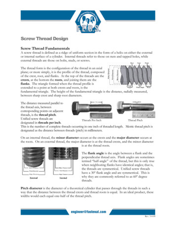
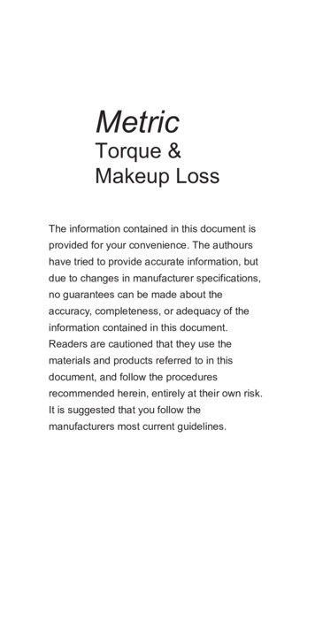
6. Chamfers and Fillets.— (a) General pur pose threads.—External threads may have thecrest corners chamfered at an angle of 45 withthe axis to a maximum depth of 0.0667/). Thiscorresponds to a maximum width of chamfer flatof 0.0945/).(b)Centralizing threads.—External threadsshall have the crest corners chamfered at an angleof 45 with the axis to a minimum depth of 0.05/)and a maximum depth of 0.0667/). This corre sponds to a minimum width of chamfer flat of0.0707/) and a maximum width of 0.0945/).(Seetable XII.2, cols. 6 and 7.)External threads for classes 2C, 3C, and 4Cmay have a fillet at the minor diameter not greaterthan 0.1/) and for classes 5C and 6C the minimumfillet shall be 0.07/), and the maximum fillet 0.1 p.Internal threads of all classes may have a filletat the major diameter not greater than 0.06/).7. Basic Dimensions.—(a) General.—For gen eral purpose threads, the basic thread form dimen sions for the most generally used pitches are givenin table XII. 1; the basic thread form is symmet rical and is illustrated in figure XII. 1.For centralizing threads, the basic dimensionsfor the most generally used pitches are given intable XII.2; the basic thread form is symmetricaland is illustrated in figure XII.2.TableXII. 1—Basic dimensions, general purpose AcmethreadsWidth of flat at:Threadsperinch,Pitch,PnTotalHeight of height ofthreadthread,(basic), hs h 4-0.5A 0.5pallow ance aCrest ofinternalthread(basic),Root ofinternalthread,Fcn 0.3707p0.3707p—0.259Xallowance a567in.in.in.t 0.5pF,n i21614121080. 06250.07143.08333. 10000.125000.03125.03571.04167. 05000.062500.0362. 0407. 0467.0600.07250. 03125. 03571.04167.05000.062500. 0232. 0265. 0309.0371.04630. 0206.0239.0283.0319.0411654324-. 16667.20000.25000. 33333. 40000.08333.10000.12500.16667. 20000.0933. 1100. 1350. 1767.2100.08333. 10000.12500. 16667. 20000.0618.0741.0927. 1236. 1483. 0566. 0689. 0875.1184.14312ihiy31.50000. 66667. 750001. 00000. 25000. 33333. 37500. 50000.2600. 3433.3850.5100. 25000.33333.37500. 50000. 1853.2471. 2780.3707.1802. 2419.2728.3655in.3in.4in.“ For allowance, see table XII.4, col. 3.Figure XII.1.—General purpose Acme thread form.Notation2a 29 a 14 30'p pitch7i number of threads per inchIV number of turns per inchh basic height of thread 0.5pf thickness of thread 0.5pF„„ 0.3707p basic width of flat of crest of internal threadFc„ 0.3707p basie width of flat of crest of external threadF,„ 0.3707p—0.259X(major-diameter allowance on internal thread)Fr, 0.3707p—0.259X (minor-diameter allowance on external thread—pitch-diameter allowance on external thread).2Threadthick ness(basic),
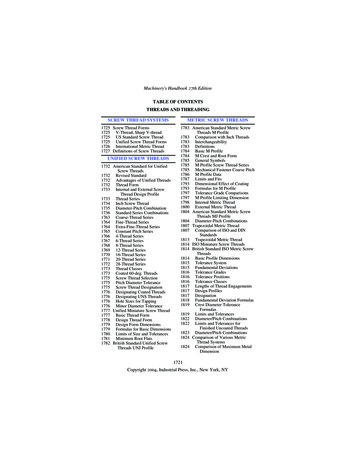
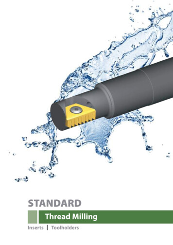
TableThreads perinch,n1Pitch,pHeight ofthread (basic),ft 0.5pXII.2—Basic dimensions, centralizing Acme threads45 chamfer crest of central izing external threadsTotal heightof thread(all externalthreads)ft, ft 0.5allowance *Thread thick ness (basic),f 0.5p5234in.in.in.Min depth,0.05p687in.in.Min width ofchamfer flat,0.0707pMax filletradius, rootof centralizingtapped hole,0.06pin.in.Fillet radius at minor diameterof centralizing screwsMin (classes5 and 6 only),0.07pMax 08333. 10000. 125000. 03125. 03571.04107.05000.062500. 0362. 0407.0467. 0600.07250.03125.03571.04167. 05000. 062500. 0031.0036.0042. 0050.00620. 0044.0050.0060.0070.00900. 0040.0040.0050. 0060.00750. 0044. 0050.0058. 0070.00880. 0062.0071. 0083. 0100.012565432 H--.16667. 20000. 25000. 33333. 40000.08333. 10000. 12500. 16667. 20000.0933. 1100. 1350. 1767.2100. 08333. 10000. 12500. 16667. .0280.0100. 0200. 0250.0333.04002l'Al Al.50000.66667. 750001.00000. 25000. 33333. 37500. 50000.2600.3433.3850.5100. 470.0530.0710.0300. 0400.0450.0600.0350.0467.0525.0700. 0500. 0667.0750. 1000* For allowance, see table XII.4, col. 3.Figure XII.2.—Centralizing Acme thread form.Notation2a 29 a 14 30'p pitchn number of threads per inchN number of turns per inchft basic height of thread 0.5 pf thickness of thread 0.5 pFcn 0.3707p basic width of flat of crest of internal threadFc, 0.3707p basic width of flat of crest of external threadFm 0.3707p—0.259 X (major-diameter allowance on internal thread).FVs 0.3707p—0.259X(minor-diameter allowance on externalthread—pitch-diameter allowance on external thread).F,n and F„ are measured from the intersections of the straight flanks and roots.3
(b) Special requirements (deviations from nomi nal diameter).—Applications requiring special ma chining processes resulting in a basic diameterother than the nominal diameters shown in tableXII.3, column 1, shall have allowances and toler ances in accordance with table XII.4, footnote a;table XII.5; and tabulated tolerances, tablesXII.6, XII.7, and XII.8.(c) Special diameters.—Special diameters notshown in table XII.3 or not divisible by }{e, shallshow the actual basic major diameter in decimalson drawings, specifications, and tools.These diameters and pitches have been carefullyselected to meet the present needs with the few est number of items, in order to reduce to a mini mum the inventory of both tools and gages.4. CLASSIFICATION AND TOLERANCES,THREADSThere are established herein three classes ofthreads for general purpose and live classes forcentralizing Acme threads, as follows:Type of thread3. STANDARD ACME THREAD SERIES* 1 2 3There has been selected a series of diametersand associated pitches of Acme threads listed intable XII.3 which is recommended as preferred.3 When Acme centralizing threads are produced in single units or in verysmall quantities (and principally in sizes larger than the range of commercialtaps and dies) where the manufacturing process employs cutting tools (suchas lathe cutting), it may be economically advantageous and therefore desir able to have the centralizing control of the mating threads located at the minordiameters.Particularly under the above-mentioned type of manufacturing, the ad vantages cited for minor diameter centralizing control over centralizing con trol at the major diameters of the mating threads are:(1) Greater ease and faster checking of machined thread dimensions. Itis much easier to measure the minor diameter (root) of the external thread andthe mating minor diameter (crest or bore.) of the internal thread than it is todetermine the major diameter (root) of the internal thread and the majordiameter (crest or turn) of the external thread;(2) better manufacturing control of the machined size due to greater easeof checking;(3) lower manufacturing costs.ACMEClass of threadGeneral purposeCentralizing . .2G2C.3G3C4G4C5C6CThese classes, together with the accompanyingspecifications, are for the purpose of assuring theinterchangeable manufacture of Acme threadedparts. Each user is free to select the classes bestadapted to his particular needs. It is suggestedthat external and internal threads of the same classbe used together for either general purpose orcentralizing assemblies. If
Foreword . This volume is the third of a series of three into which the 1957 edition of NBS Handbook H28 is divided. Part I, published in September 1957, includes standards for screw threads