Transcription
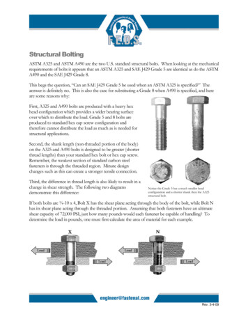
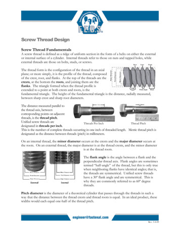
Screw Thread DesignScrew Thread FundamentalsA screw thread is defined as a ridge of uniform section in the form of a helix on either the externalor internal surface of a cylinder. Internal threads refer to those on nuts and tapped holes, whileexternal threads are those on bolts, studs, or screws.The thread form is the configuration of the thread in an axialplane; or more simply, it is the profile of the thread, composedof the crest, root, and flanks. At the top of the threads are thecrests, at the bottom the roots, and joining them are theflanks. The triangle formed when the thread profile isextended to a point at both crests and roots, is thefundamental triangle. The height of the fundamental triangle is the distance, radially measured,between sharp crest and sharp root diameters.The distance measured parallel tothe thread axis, betweencorresponding points on adjacentthreads, is the thread pitch.Unified screw threads areThreads Per InchThread Pitchdesignated in threads per inch.This is the number of complete threads occurring in one inch of threaded length. Metric thread pitch isdesignated as the distance between threads (pitch) in millimeters.On an internal thread, the minor diameter occurs at the crests and the major diameter occurs atthe roots. On an external thread, the major diameter is at the thread crests, and the minor diameteris at the thread roots.The flank angle is the angle between a flank and theperpendicular thread axis. Flank angles are sometimestermed “half-angle” of the thread, but this is only truewhen neighboring flanks have identical angles; that is,the threads are symmetrical. Unified screw threadshave a 30º flank angle and are symmetrical. This iswhy they are commonly referred to as 60º degreethreads.Pitch diameter is the diameter of a theoretical cylinder that passes through the threads in such away that the distance between the thread crests and thread roots is equal. In an ideal product, thesewidths would each equal one-half of the thread pitch.Rev. 3-4-09
An intentional clearance is created between mating threads when the nut and bolt are manufactured.This clearance is known as the allowance. Having an allowance ensures that when the threads aremanufactured there will be a positive space between them. For fasteners, the allowance is generallyapplied to the external thread. Tolerances are specified amounts by which dimensions arepermitted to vary for convenience of manufacturing. The tolerance is the difference between themaximum and minimum permitted limits.Thread FitThread fit is a combination of allowances and tolerances and a measure of tightness or loosenessbetween them. A clearance fit is one that provides a free running assembly and an interference fitis one that has a positive interference thus requiring tools for the initial run-down of the nut.For Unified inch screw threads there are six standard classes of fit: 1B, 2B, and 3B for internalthreads; and 1A, 2A, and 3A for external threads. All are considered clearance fits. That is, theyassemble without interference. The higher the class number, the tighter the fit. The ‘A’ designatesan external thread, and ‘B’ designates an internal thread. Classes 1A and 1B are considered an extremely loose tolerance thread fit. This class issuited for quick and easy assembly and disassembly. Outside of low-carbon threaded rod ormachine screws, this thread fit is rarely specified. Classes 2A and 2B offer optimum thread fit that balances fastener performance,manufacturing, economy, and convenience. Nearly 90% of all commercial and industrialfasteners use this class of thread fit. Classes 3A and 3B are suited for close tolerance fasteners. These fasteners are intended forservice where safety is a critical design consideration. This class of fit has restrictivetolerances and no allowance. Socket products generally have a 3A thread fit.The following illustration demonstrates thepitch diameter allowances on a ¾-10 bolt andnut.The axial distance through which the fullyformed threads of both the nut and bolt are incontact is called the length of threadengagement. The depth of threadengagement is the distance the threads overlapin a radial direction. The length of threadengagement is one of the key strength aspectsand one of the few which the designer may beable to control.Rev. 3-4-09
Per the acceptance requirements of ASME B1.3, System 21, the allowancespecified for the Class 2A external threads is used to accommodate theplating thickness. The plain finished parts (or plated parts prior to plating)would be tested for adherence to these tolerances with a 2A Go/No-Gothread gauge. The 2A Go gauge would ensure the pitch diameter fallsbelow the maximum requirement; the No-Go gauge would verify that thepitch diameter is above the minimum requirement. A standard electro-zincplated 2A part would be gauged with the Class 3A Go (due to the platingmetal thickness) and 2A No-Go gauge after plating.Go and No-Go Gauges arethreaded rings that are tappedin such a way that they ensureproper tolerancing of parts.Similar devices are availablefor internally threadedfasteners.Thread damages such as dents, scrapes,nicks, or gouges and plating build-up arenot cause for rejections unless theyimpair function and usability. Threadsthat do not freely accept the appropriateGo ring gauge shall be inspected byallowing the screwing of the gauge withmaximum allowable torque value of:Torque 145 x d3 (for inch series), where Torque is in-lbs. and d isdiameter in inches- IFI 166Minor thread nicking on externalthreads may still be foundacceptable.Torque 0.001 x d3 (for metric series), where Torque is Nm and d is diameter in mm- IFI 566Thread SeriesThere are three standard thread series in the Unified screw thread system that are highly importantfor fasteners: UNC (coarse), UNF (fine), and 8-UN (8 thread). A chart listing the standards sizesand thread pitches with their respective thread stress areas is listed in the Fastenal TechnicalReference Guide, along with a special series designated UNS.Below are some of the aspects of fine and coarse threads.Rev. 3-4-09
Fine ThreadCoarse Thread Since they have larger stressareas the bolts are strongerin tension Stripping strengths are greaterfor the same length ofengagement Their larger minordiameters develop highertorsional and transverseshear strengths Improved fatigue resistance Less likely to cross thread Quicker assembly anddisassembly Tap better in brittle materials Larger thread allowancesallow for thicker platings andcoatings They can tap better in thinwalled membersWith their smaller helixangle, they permit closeradjustment accuracyNumerous arguments have been made for using either fine or coarse threads; however, with theincrease in automated assembly processes, bias towards the coarse thread series has developed.UNR ThreadsThe UNR thread is a modified version of a standard UN thread. The single difference is amandatory root radius with limits of 0.108 to 0.144 times the thread pitch. When first introduceddecades ago, it was necessary to specify UNR (rounded root) threads. Today, all fasteners that areroll threaded should have a UNR thread because thread rolling dies with rounded crests are now thestandard method for manufacturing most threads.UNJ ThreadsUNJ thread is a thread form having root radius limits of 0.150 to 0.180 times the thread pitch.With these enlarged radii, minor diameters of external thread increase and intrude beyond the basicprofile of the UN and UNR thread forms. Consequently, to offset the possibility of interferencebetween mating threads, the minor diameters of the UNJ internal threads had to be increased.3A/3B thread tolerances are the standard for UNJ threads. UNJ threads are now the standard foraerospace fasteners and have some usage in highly specialized industrial applications.UNJ bolts are like UNR, but the curve of the thread root is gentler which requires that it beshallower. In fact, the thread root is so shallow that the bolt thread cannot mate with a UN nut, sothere is a UNJ nut specification as well.Thread ProductionThreads can be produced by either cutting or rolling operations. The shank of a blank designed forcut threading will be full-size from the fillet under the head to the end of the bolt. Producing cutRev. 3-4-09
threads involves removing the material from a bolt blank with a cutting die or lathe in order toproduce the thread. This interrupts the grain flow of the material.Rolled threads are formed by rolling the reduced diameter (approximately equal to the pitchdiameter) portion of the shank between two reciprocating serrated dies. The dies apply pressure,compressing the minor diameter (thread roots) and forcing that material up to form the majordiameter (thread crests). Imagine squeezing a balloon with your hand; you compress with yourfingers to form the valley, while allowing part of the balloon to expand between your fingers. This isthe concept behind roll threading. Rolled threads have several advantages: more accurate anduniform thread dimension, smoother thread surface, and generally greater thread strength(particularly fatigue and shear strength).Thread cutting requires the least amount of tooling costs. It is generally only used for large diameteror non-standard externally threaded fasteners. Thread cutting is still the most commonly usedmethod for internal threads.Thread StrengthTwo fundamentals must be considered when designing a threaded connection.1. Ensure that the threaded fasteners were manufactured to a current ASTM, ANSI, DIN, ISO orother recognized standard.2. Ensure that the design promotes bolts to break in tension prior to the female and/or malethreads stripping. A broken bolt is an obvious failure. However, when the threads strip prior tothe bolt breaking, the failure may go unnoticed until after the fastener is put in service.Rev. 3-4-09
The strength of bolts loaded in tension can beeasily determined by the ultimate tensilestrength. To determine the amount of forcerequired to break a bolt, multiply its ultimatetensile strength by its tensile stress area, AsInternal Thread Strength FormulaF Su * AtsSu shear strength of the nut or tapped materialAts cross-sectional area through which the shear occursDetermining the strength of the threads is more complicated. Since the male threads pull past thefemale threads, or vice-versa, the threads fail in shear and not in tension. Therefore, the strippingstrength of an assembly depends on the shear strength of the nut and bolt materials.Formula for Ats (when shear occurs at the roots of the thread)Ats n Le Dsmin[1/(2n) 0.57735 (Dsmin – Enmax)]Dsmin min major dia.Enmax max pitchn thread perof external threadsdia. of internal threadsinchLe length of threadengagementTo determine the force required to strip the threads, multiply the shear strength by the crosssectional area being sheared. The difficulty lies in determining thecross sectional area in which the shear will occur. Here are threepossible scenarios for this type of failure.1. The nut material is stronger than the bolt material. In thisexample, the nut threads will shear out the bolt threads. Thefailure will occur at the root of the bolt threads.2. The bolt material is stronger than the nut material. In thisscenario, the bolt threads will shear out the nut threads. Thefailure will occur at the root of the nut threads.3. The nut and bolt are the same strength. In this scenario, boththreads will strip simultaneously. This failure will occur at thepitch line.Taking proper precautions duringthe design phase is vital toavoiding thread failure. Once thefirst engaged thread begins toshear, the threads behind it willalso shear in rapid succession.The tensile strength of most fasteners is usually specified, whereasshear strength is not. In order to avoid shearing the threads, ensurethat the length of engagement between the internal and external thread is long enough to provideadequate cross-sectional thread area.Failure scenarios #1 and #3 can typically be avoided by ensuring proper thread engagement. Withproper engagement, those scenarios would result in a tensile failure of the bolt rather than threadstripping.Rev. 3-4-09
Generally the hardness and the actual material strength of a nutis less than the bolt. For example, if you look at the hardness ofan SAE J995 Grade 8 nut (HRC 24-32 up to 5/8-in diameter), itis likely to be less than the SAE J429 Grade 8 bolt (HRC 33-39).This is designed to yield the nut threads to ensure the load is notcarried solely by the first thread. As the thread yields, the load isfurther distributed to the next five threads. Even with the loaddistribution, the first engaged thread still takes the majority ofthe load. In a typical 7/8-9 Grade 8 nut, the first engagedthread carries 34% of the load. Using internally threaded materials with higher strengths andhardness can often result in fatigue and/or loosening.The strength capacities of standard nuts are listed as the nut’s proof stress. This should not beconfused with the proof strength of the bolts. Proof stress is the ultimate load the nut can supportwithout thread failure. For design purposes, the most important aspect of choosing the appropriatenut is to select a nut with a proof stress equal to or greater than the ultimate tensile strength of thebolt.Caution: It appears that one could theoretically increase the thread strength by increasing the lengthof engagement. However, as illustrated in the Load Distribution chart above, the first thread will betaking the majority of the applied load. For carbon steel fasteners (including tapped holes) thelength of engagement would be limited to approximately one nominal diameter (approximately 11/2 times the diameter for aluminum). After that, there is no appreciable increase in strength. Oncethe applied load has exceeded the first thread’s capacity, it will fail and subsequently cause theremaining threads to fail in success
uniform thread dimension, smoother thread surface, and generally greater thread strength (particularly fatigue and shear strength). Thread cutting requires the least amount of tooling costs. It is generally only used for large diameter or non-standard externally threaded fasteners. Thread cutting is still the most commonly used method for internal threads. Thread Strength Two fundamentals must .