Transcription
Machinery's Handbook 27th EditionTABLE OF CONTENTSTHREADS AND THREADINGSCREW THREAD SYSTEMS1725 Screw Thread Forms1725 V-Thread, Sharp V-thread1725 US Standard Screw Thread1725 Unified Screw Thread Forms1726 International Metric Thread1727 Definitions of Screw ThreadsUNIFIED SCREW THREADS1732 American Standard for UnifiedScrew Threads1732 Revised Standard1732 Advantages of Unified Threads1732 Thread Form1733 Internal and External ScrewThread Design Profile1733 Thread Series1734 Inch Screw Thread1735 Diameter-Pitch Combination1736 Standard Series Combinations1763 Coarse-Thread Series1764 Fine-Thread Series1764 Extra-Fine-Thread Series1765 Constant Pitch Series1766 4-Thread Series1767 6-Thread Series1768 8-Thread Series1769 12-Thread Series1770 16-Thread Series1771 20-Thread Series1772 28-Thread Series1773 Thread Classes1773 Coated 60-deg. Threads1775 Screw Thread Selection1775 Pitch Diameter Tolerance1775 Screw Thread Designation1776 Designating Coated Threads1776 Designating UNS Threads1776 Hole Sizes for Tapping1776 Minor Diameter Tolerance1777 Unified Miniature Screw Thread1777 Basic Thread Form1778 Design Thread Form1779 Design Form Dimensions1779 Formulas for Basic Dimensions1780 Limits of Size and Tolerances1781 Minimum Root Flats1782 British Standard Unified ScrewThreads UNJ ProfileMETRIC SCREW THREADS1783 American Standard Metric ScrewThreads M Profile1783 Comparison with Inch Threads1783 Interchangeability1783 Definitions1784 Basic M Profile1784 M Crest and Root Form1785 General Symbols1785 M Profile Screw Thread Series1785 Mechanical Fastener Coarse Pitch1786 M Profile Data1787 Limits and Fits1793 Dimensional Effect of Coating1793 Formulas for M Profile1797 Tolerance Grade Comparisons1797 M Profile Limiting Dimension1798 Internal Metric Thread1800 External Metric Thread1804 American Standard Metric ScrewThreads MJ Profile1804 Diameter-Pitch Combinations1807 Trapezoidal Metric Thread1807 Comparison of ISO and DINStandards1813 Trapezoidal Metric Thread1814 ISO Miniature Screw Threads1814 British Standard ISO Metric ScrewThreads1814 Basic Profile Dimensions1815 Tolerance System1815 Fundamental Deviations1816 Tolerance Grades1816 Tolerance Positions1816 Tolerance Classes1817 Lengths of Thread Engagements1817 Design Profiles1817 Designation1818 Fundamental Deviation Formulas1819 Crest Diameter ToleranceFormulas1819 Limits and Tolerances1822 Diameter/Pitch Combinations1822 Limits and Tolerances forFinished Uncoated Threads1823 Diameter/Pitch Combinations1824 Comparison of Various MetricThread Systems1824 Comparison of Maximum MetalDimension1721Copyright 2004, Industrial Press, Inc., New York, NY
Machinery's Handbook 27th EditionTABLE OF CONTENTSTHREADS AND THREADINGACME SCREW 843184318461846184618481848WHITWORTH THREADSGeneral Purpose Acme ThreadsAcme Thread FormAcme Thread AbbreviationsDesignationBasic DimensionsFormulas for DiametersLimiting DimensionsSingle-Start Screw Thread DataPitch Diameter AllowancesMultiple Start Acme ThreadsPitch Diameter TolerancesCentralizing Acme ThreadsBasic DimensionsFormulas for DiametersLimiting DimensionsScrew Thread DataPitch Diameter AllowancesPitch Diameter TolerancesTolerances and AllowancesDesignationAcme Centralizing ThreadStub Acme ThreadsBasic DimensionsFormulas for DiametersLimiting DimensionsStub Acme Thread DesignationsAlternative Stub Acme ThreadsFormer 60-Degree Stub ThreadSquare Thread10-Degree Square Thread1857 British Standard Whitworth (BSW)and Fine (BSF) Threads1857 Standard Thread Form1857 Whitworth Standard Thread Form1857 Tolerance Formulas1858 Basic DimensionsPIPE AND HOSE THREADSBUTTRESS THREADS1849 Threads of Buttress Form1849 British Standard Buttress Threads1849 Lowenherz or Löwenherz Thread1850 Buttress Inch Screw Threads1850 American National StandardButtress Inch Screw Threads1850 Pitch Combinations1850 Basic Dimensions1850 Buttress Thread1850 Symbols and Form1851 Buttress Thread Tolerances1851 Class 2 Tolerances1855 Allowances for Easy Assembly1855 External Thread Allowances1856 Buttress Thread Designations1856 Designation Sequence1860 American National Standard PipeThreads1860 Thread Designation and Notation1860 Taper Pipe Thread1861 Basic Dimensions1862 Engagement1862 Tolerances on Thread Elements1863 Limits on Crest and Root1864 Pipe Couplings1864 Railing Joint1864 Straight Pipe Threads1864 Mechanical Joints1866 Dryseal Pipe Thread1866 Limits on Crest and Root1866 Types of Dryseal Pipe Thread1866 Limitation of Assembly1868 Tap Drill Sizes1868 Special Dryseal Threads1869 Limitations for Combinations1869 British Standard Pipe Threads1869 Non-pressure-tight Joints1870 Basic Sizes1870 Pressure-tight Joints1871 Limits of Size1872 Hose Coupling Screw Threads1872 ANSI Standard1873 Hose Coupling Threads1874 Screw Thread Length1874 Fire Hose Connection1875 Basic Dimensions1876 Limits of SizeOTHER THREADS1877 Interference-Fit Threads1878 Design and Application Data1879 External Thread Dimension1879 Internal Thread Dimension1880 Engagement Lengths1881 Allowances for Coarse Thread1881 Tolerances for Coarse Thread1722Copyright 2004, Industrial Press, Inc., New York, NY
Machinery's Handbook 27th EditionTABLE OF CONTENTSTHREADS AND THREADINGOTHER THREADSMEASURING SCREW THREADS(Continued)(Continued)1882 Variations in Lead and Diameter1883 Spark Plug Threads1883 BS Spark Plugs1883 SAE Spark Plugs1884 Lamp Base and Socket Threads1885 Instrument and MicroscopeThreads1885 British Association Thread1886 Instrument Makers’ Screw Thread1886 Microscope Objective Thread1889 Swiss Screw Thread1890 Historical and Miscellaneous1890 Aero-Thread1890 Briggs Pipe Thread1890 Casing Thread1891 Cordeaux Thread1891 Dardelet Thread1891 “Drunken” Thread1891 Echols Thread1891 French Thread (S.F.)1891 Harvey Grip Thread1892 Lloyd & Lloyd Thread1892 Lock-Nut Pipe Thread1892 Philadelphia Carriage Bolt Thread1892 SAE Standard Screw Thread1892 Sellers Screw Thread1905 Checking Pitch Diameter1905 Checking Thread Thickness1906 Wire Sizes1906 Checking Thread Angle1907 Best Wire Diameters1909 Taper Screw Threads1910 Buttress Threads1911 Thread Gages1911 Thread Gage Classification1911 Gages for Unified Inch Threads1914 Thread Forms of Gages1914 Thread Gage Tolerances1916 Tolerances for Cylindrical Gages1918 Formulas for LimitsMEASURING SCREW THREADS1893 Measuring Screw Threads1893 Pitch and Lead of Screw Threads1893 Thread Micrometers1894 Ball-point Micrometers1894 Three-wire Method1895 Classes of Formulas1895 Screw Thread Profiles1895 Accuracy of Formulas1896 Best Wire Sizes1897 Measuring Wire Accuracy1897 Measuring or Contact Pressure1897 Three-Wire Formulas1898 NIST General Formula1899 Formulas for Pitch Diameters1899 Effect of Small Thread Angle1901 Dimensions Over Wires1901 Formula Including Lead Angle1902 Measuring Whitworth Threads1903 Buckingham Exact Formula1904 Accuracy of FormulasAcme and Stub Acme ThreadTAPPING AND THREADCUTTING1919 Selection of Taps1921 Tap Rake Angles1921 Cutting Speed1921 Tapping Specific Materials1924 Diameter of Tap Drill1925 Hole Size Limits1933 Tap Drill Sizes1934 Tap Drills and Clearance Drills1934 Tolerances of Tapped Holes1935 Hole Sizes before Tapping1936 Miniature Screw Threads1937 Tapping Drill Sizes1937 ISO Metric Threads1938 Clearance Holes1939 Cold Form Tapping1940 Core Hole Sizes1941 Tap Drill Sizes1941 Removing a Broken Tap1941 Tap Drills for Pipe Taps1941 Power for Pipe Taps1942 High-Speed CNC Tapping1943 Coolant for Tapping1943 Combined Drilling and Tapping1944 Relief Angles for Cutting Tools1946 Lathe Change Gears1946 Change Gears for Thread Cutting1946 Compound Gearing1946 Fractional Threads1947 Change Gears for Metric Pitches1947 Change Gears for FractionalRatios1723Copyright 2004, Industrial Press, Inc., New York, NY
Machinery's Handbook 27th EditionTABLE OF CONTENTSTHREADS AND THREADINGTAPPING AND THREADCUTTINGTHREAD tinued)1948195019501951Quick-Change Gearbox OutputFinding Accurate Gear RatiosLathe Change-gearsRelieving Helical-Fluted HobsTHREAD ROLLING1952 Thread-Rolling Machine1952 Flat-Die Type1952 Cylindrical-Die Type1952 Rate of Production1953 Precision Thread Rolling1953 Steels for Thread Rolling1953 Diameter of Blank1953 Automatic Screw Machines1954 Factors Governing the Diameter1954 Diameter of Threading Roll1954 Kind of Thread on Roll1955 Application of Thread Roll1955 Thread Rolling Speeds and FeedsTHREAD GRINDING1957 Thread Grinding1957 Wheels for Thread Grinding1957 Single-Edge Wheel1958 Edges for Roughing and Finishing1958 Multi-ribbed Wheels1959 Ribbed Wheel for Fine Pitches1959 Solid Grinding Threads1959 Number of Wheel Passes1959 Wheel and Work Rotation1960 Wheel Speeds1960 Work Speeds1960 Truing Grinding Wheels1960 Wheel Hardness or Grade1961 Grain Size1961 Grinding by Centerless MethodTHREAD MILLING1962 Thread Milling1962 Single-cutter Method1962 Multiple-cutter Method1963 Planetary Method1963 Classes of Work1964 Pitches of Die-cut Threads1964 Changing Pitch of Screw1964 Helical Milling1964 Lead of a Milling Machine19811982198219821982Change Gears for Helical MillingShort-lead MillingHelixHelix AnglesChange Gears for Different LeadsLead of HelixChange Gears and AnglesDetermining Helix AngleFor Given Lead and DiameterFor Given AngleFor Given LeadAnd Lead Given DP and TeethLead of Tooth Given Pitch Radiusand Helix AngleSIMPLE, COMPOUND,DIFFERENTIAL, AND BLOCKINDEXING1983 Milling Machine Indexing1983 Hole Circles1983 Holes in Brown & Sharpe1983 Holes in Cincinnati1983 Simple Indexing1984 Compound Indexing1985 Simple and Compound Indexing1990 Angular Indexing1990 Tables for Angular Indexing1991 Angular Values of CincinnatiIndex1992 Accurate Angular Indexing2007 Indexing for Small Angles2008 Differential Indexing2008 Ratio of Gearing2009 To Find the Indexing Movement2009 Use of Idler Gears2009 Compound Gearing2010 Check Number of Divisions2011 Simple and Different Indexing2017 Indexing Movements of Plate2018 Indexing Movements for HighNumbers2021 Indexing Tables2021 Block or Multiple Indexing2023 Indexing Movements for 60Tooth2024 Linear Indexing for Rack Cutting2024 Linear Indexing Movements2025 Counter Milling1724Copyright 2004, Industrial Press, Inc., New York, NY
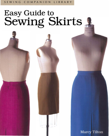
Machinery's Handbook 27th EditionTHREADS AND THREADING1725SCREW THREAD SYSTEMSScrew Thread FormsOf the various screw thread forms which have been developed, the most used are thosehaving symmetrical sides inclined at equal angles with a vertical center line through thethread apex. Present-day examples of such threads would include the Unified, the Whitworth and the Acme forms. One of the early forms was the Sharp V which is now used onlyoccasionally. Symmetrical threads are relatively easy to manufacture and inspect andhence are widely used on mass-produced general-purpose threaded fasteners of all types.In addition to general-purpose fastener applications, certain threads are used to repeatedlymove or translate machine parts against heavy loads. For these so-called translationthreads a stronger form is required. The most widely used translation thread forms are thesquare, the Acme, and the buttress. Of these, the square thread is the most efficient, but it isalso the most difficult to cut owing to its parallel sides and it cannot be adjusted to compensate for wear. Although less efficient, the Acme form of thread has none of the disadvantages of the square form and has the advantage of being somewhat stronger. The buttressform is used for translation of loads in one direction only because of its non-symmetricalform and combines the high efficiency and strength of the square thread with the ease ofcutting and adjustment of the Acme thread.V-Thread, Sharp V-thread.—The sides of the thread form an angle of 60 degrees witheach other. The top and bottom or root of this thread form are theoretically sharp, but inactual practice the thread is made with a slight flat, owing to the difficulty of producing aperfectly sharp edge and because of the tendency of such an edge to wear away or becomebattered. This flat is usually equal to about one twenty-fifth of the pitch, although there isno generally recognized standard.Owing to the difficulties connected with the V-thread, the tap manufacturers agreed in 1909 to discontinue the making of sharp Vthread taps, except when ordered. One advantage of the V-thread isthat the same cutting tool may be used for all pitches, whereas,with the American Standard form, the width of the point or the flatvaries according to the pitch.The V-thread is regarded as a good form where a steam-tight jointis necessary, and many of the taps used on locomotive work havethis form of thread. Some modified V-threads, for locomotive boiler taps particularly, havea depth of 0.8 pitch.The American Standard screw thread is used largely in preference to the sharp V-threadbecause it has several advantages; see American Standard for Unified Screw Threads. If p pitch of thread, and d depth of thread, then0.866d p cos 30 deg. 0.866 p ----No. of threads per inchUnited States Standard Screw Thread.—William Sellers of Philadelphia, in a paperread before the Franklin Institute in 1864, originally proposed the screw thread system thatlater became known as the U. S. Standard system for screw threads. A report was made tothe United States Navy in May, 1868, in which the Sellers system was recommended as astandard for the Navy Department, which accounts for the name of U. S. Standard. TheAmerican Standard Screw Thread system is a further development of the United StatesStandard. The thread form which is known as the American (National) form is the same asthe United States Standard form. See American Standard for Unified Screw Threads.American National and Unified Screw Thread Forms.—The American National form(formerly known as the United States Standard) was
1797 M Profile Limiting Dimension 1798 Internal Metric Thread 1800 External Metric Thread 1804 American Standard Metric Screw Threads MJ Profile 1804 Diameter-Pitch Combinations 1807 Trapezoidal Metric Thread 1807 Comparison of ISO and DIN Standards 1813 Trapezoidal Metric Thread 1814 ISO Miniature Screw Threads 1814 British Standard ISO Metric Screw Threads 1814 Basic