Transcription
MPLS VPNl.cittadini, m.cola, g.di battista
motivations
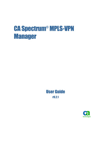
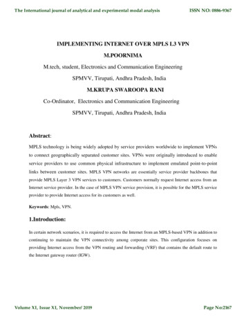
customer’s problem a customer (e.g., private company, publicadministration, etc.) has severalgeographically distributed sites and would liketo connect them into a unique IP network– ideally it would like to have “wires” connecting itssites
provider’s target a provider owns a network infrastructure withmany distributed PoPs (Points of Presence)and would like to exploit it to offer IP levelconnectivity services to its customers– it would like to sell virtual wires (where IP packetscan flow) to its customers
provider and customersCustomer 2Customer 1Torino PoPMilano PoP212.102.68.0/24193.192.173.0/24provider’s network193.192.172.0/24212.102.67.0/24Roma PoPCustomer 2Customer 1
customer’s constraints keep the addressing unchanged isolation from different customer's traffic quality of service
provider’s constraints low configuration and maintenance costs no performance penalties– performance in the backbone should only dependon traffic, not on the number of supported VPNsor on the number of supported sites
vendor’s targets sell many routers– possibly expensive carrier-grade machines move the focus from old (and already oversold) ATM & ATM-like technologies to new(and with a growing market) technologies
meeting pointbetween customers, providers, and vendors VPN – Virtual Private Network: behaves like aphysical private network, but it's virtualimplemented with MPLS – Multi Protocol Label Switching(swapping): highly scalable, protocol-agnostic,data-carrying mechanism
MPLS
MPLS in a nutshell MPLS vs OSIpicture from wikipedia
MPLS in a nutshell MPLS packet– encapsulates transported packets with an MPLSheader, containing one or more labels (labelstack)– each label stack entry contains 4 fields: label value (20 bits) traffic class field for QoS and ECN - Explicit CongestionNotification (3 bits) bottom of stack flag (1 bit) ttl (8 bits)
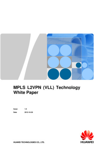
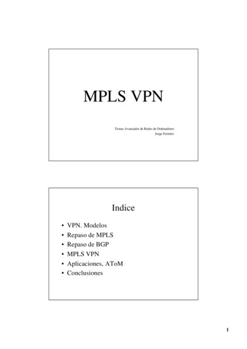
an interconnection scenarioCustomer 2Customer 1Torino PoPMilano PoP321.802/302.11.12 331280.1.1.4/3080.1.1.8/30212.102.68.0/241VPN 1VPN 1.1.0/30AS 10080.0.0.0/832212.102.67.0/24Roma PoPCustomer 2Customer 1
CE - customer edge routersCustomer 2Customer 1Torino PoPMilano PoP321VPN 2212.102.68.0/24122 3312VPN 24Roma PoPCustomer 2Customer 1
PE – provider edge routersCustomer 2Customer 1Torino PoPMilano PoP321VPN 2212.102.68.0/24122 3312VPN 24Roma PoPCustomer 2Customer 1
P – provider routersCustomer 2Customer 1Torino PoPMilano PoP321VPN 2212.102.68.0/24122 3312VPN 24Roma PoPCustomer 2Customer 1
router names in the VPN language P – provider router– core/backbone router PE – provider edge router– customer facing router CE – customer edge router– the customer device a PE router talks to
how tocheckmate VPNs in three moves:(1) make PEs reachable each other using IP,(2) use BGP for announcing customer prefixes, and(3) use MPLS for tunnels inside the backbone
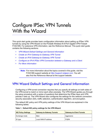
1st move – IP reachability of the PE’s the first thing to do is to assign an IP loopbackaddress to each PE and to ensure IPreachability among PEs in the backbone– ignore all the other issues– inside backbone use addresses that are notannounced outside (e.g. private addresses) loopback addresses are propagated by an IGP– OSPF, IS-IS, .
loopbacks of PEs80.80.80.4/32Torino PoPMilano PoP11.802/302.11.12 3Customer 180.1.1.8/3080.80.80.5/3280.1.1.16/30Customer 23180.1.1.4/3021180.1.1.0/30AS 10080.0.0.0/8Roma PoPCustomer 280.80.80.1/32Customer 1
a tempting solution implement VPNs using IP-in-IP tunnels (orsimilar technologies) between PEs’ loopbacks drawbacks– difficult to configure– quadratic number of configurationshence, this solution is discarded
2nd move – use BGP to announcecustomer prefixes MP-BGP, a variation of BGP, is used each PE establishes an iBGP peering with allother PEs– usage of route reflectors for scaling customer’s networks are announced withinthe peerings
BGP peeringsCustomer 2Customer 1Torino PoPMilano PoP321.802/302.11.12 331280.1.1.4/3011.080.1.1193.192.172.0/24hey guys, to reach212.102.67.0/24 ofCustomer 1 and193.192.172.0/24 ofCustomer 2send traffic to me/30AS 10080.0.0.0/880.1.1.8/30212.102.68.0/241VPN 1VPN 280.1.1.16/30193.192.173.0/2432212.102.67.0/24Roma PoPCustomer 2Customer 1
3rd move – use MPLS for tunnels an IP packet of a customer, coming from a CE,is encapsulated from the PE near to thesource into an MPLS packet the PE near to the source sends the packet tothe PE (loopback) near to the destination the IP packet traverses the backbone into anMPLS envelope
MPLS labels and VPN’s two labels are pushed into the MPLS packetsstack– the bottom one denotes the VPN: it is used in away similar to the VLAN tags of IEEE 802.1Q remains unchanged for the entire travel of the packetfrom origin PE to destination PE– the top one is used for label swapping it is, in general, changed at each hop of the travel fromPE to PE a first pop from the stack is done at the penultimaterouter encountered in the travel
how to find a route to loopbacks? who constructs the label-swapping data planeof MPLS? in other words: in which way a P or a PEknows which is the correct path to the targetPE (loopback)?LDP – Label Distribution Protocolis one option for this
LDP LDP constructs the Label Switched Paths(LSPs) to reach each PE loopback by simplyimporting this information from the IP dataplane– remeber 1st move: the IP data plane knows howto reach loopbacks – it has been setup by an IGP
technology and details
data- and control-planes to understand how MPLS operates, let’s reviewthe mate-in-3 1st move: IP data-plane– build IP routing tables (OSPF, IS-IS, static )– ensure reachability of PEs’ loopback interfaces 2nd move: BGP control-plane– ensure that VPN prefixes are distributed among PEs 3rd move: MPLS data-plane– build label switching tables (LFIBs) with LDP– ensure availability of LSPs (Label Switched Paths) thatconnect each pair of PEs
80.80.80.5/32Torino PoPMilano PoP32212.102.68.0/2411.802/302.11.12 0/24VPN 2Customer 1VPN 1Customer 2move #1: IP 30AS 10080.0.0.0/832212.102.67.0/24Roma PoPCustomer 280.80.80.1/32Customer 1
move #1: IP data-planeTorino PoPMilano PoP11.802/302.11.12 3180.1.1.4/302/31.0180.1.LER1 show ip route AS 100Codes: C – connected, O – OSPF80.0.0.0/8[.]C 80.80.80.1/32Lo0O 80.80.80.4/32 via 80.1.1.2,GE1/0O 80.80.80.5/32 via 80.1.1.2,GE1/0[.]01Roma PoP80.80.80.1/32Goal: ensureconnectivity of PEs’loopback interfaces
move #1: IP data-planeTorino PoPMilano PoP11.802/302.11.12 3380.1.1.4/3021.0/301180.1.1LSR2 show ip routeASO100Codes: C – connected,– OSPF[.]80.0.0.0/8O 80.80.80.1/32 via 80.1.1.5,GE1/0O 80.80.80.4/32 via 80.1.1.14,GE3/0O 80.80.80.5/32 via 6/3080.80.80.5/32Roma PoP80.80.80.1/32Goal: ensureconnectivity of PEs’loopback interfaces
move #1: IP data-planeTorino PoPMilano PoP11.802/302.11.12 3180.1.1.4/3021180.1.1.0/30AS 10080.0.0.0/8Roma PoP80.80.80.1/32OSPFweight:500
IP data-plane: observations IP data-plane must ensure reachability of PEs’loopback interfaces– other prefixes (e.g., point-to-point links) areuseless for MPLS but they can be used for other purposes, e.g., networkmanagement (telnet, ssh, SNMP, ) any IGP (OSPF, IS-IS) can do the job static routes can do the job too, but they donot handle network dynamics– e.g., link failures
move #2: BGP control-plane80.80.80.5/3280.80.80.4/32Torino PoPMilano PoP32212.102.68.0/2411.802/302.11.12 0/24VPN 2Customer 1VPN 1Customer 211193.192.172.0/2480.1.1.0/30AS 10080.0.0.0/832212.102.67.0/24Roma PoPCustomer 280.80.80.1/32Customer 1
move #2: BGP control-planeCustomer 280.80.80.5/3280.80.80.4/32Torino PoPMilano PoPCustomer 132193.192.173.0/24LER1 show ip bgp vpnv4 allNetworkNext Hop LocPrfRoute Distinguisher: 100:11 (VPN1)* i212.102.68.0 80.80.80.4Route Distinguisher: 100:22 (VPN2)* i193.193.173.0 80.80.80.5AS 10080.0.0.0/8193.192.172.0/2432100VPN 1VPN 2212.102.68.0/24100212.102.67.0/24Roma PoPCustomer 280.80.80.1/32Customer 1
multiple routing tables on PEs PEs need to distinguish each VPN– there might be overlapping address space! solution: multiple (virtual) routing tables each customer port on PE is associated with aparticular routing table– at provisioning time ports on PE could be logical– e.g. VLANs
Virtual Routing and Forwarding(VRF) VRF - Virtual Routing and Forwarding– allows a router to have multiple forwarding tables– each table is called a VRF instance each PE maintains multiple VRF instances– one per set of directly attached sites withcommon VPN membership each VRF instance contains:– routes received from directly connected CE’s ofthe sites associated with the VRF instance– routes received from other PEs (via BGP)
VPN-IP addresses VPN-IP address Route Distinguisher (RD) IPaddress– RD Type Provider’s Autonomous SystemNumber Assigned Number no two VPNs have the same RD convert non-unique IP addresses into uniqueVPN-IP addresses avoids conflicts if customers have overlappingaddress spaces
move #3: MPLS data-plane80.80.80.5/3280.80.80.4/32Torino PoPMilano PoP32212.102.68.0/2411.802/302.11.12 0/24VPN 2Customer 1VPN 1Customer 211193.192.172.0/2480.1.1.0/30AS 10080.0.0.0/832212.102.67.0/24Roma PoPCustomer 280.80.80.1/32Customer 1
move #3: MPLS data-planeTorino PoPMilano PoP11.802/302.11.12 180.1.In Out[.]22 20[.]0AS 10080.0.0.0/8LER1 show mpls forwarding-tableRoma 3080.80.80.5/32
move #3: MPLS data-planeTorino PoPMilano PoP11.802/302.11.12 3180.1.1.4/3021180.1.1.0/30AS 10080.0.0.0/8Roma PoP80.80.80.1/32LSR1 show mpls forwarding-tableIn Out PrefixIface[.]20 2080.80.80.4/32 GE2/0[.]
move #3: MPLS data-planeTorino PoPMilano PoP11.802/302.11.12 33180.1.1.4/3021Iface/31.0180.1.In Out Prefix[.]20 Pop 80.80.80.4/32[.]0AS 100LSR2 show mpls forwarding-table80.0.0.0/8GE3/0Roma 3080.80.80.5/32
router names in the MPLS language LER –Label Edge Router– a router which first encapsulates a packet insidean MPLS LSP LSR – Label Switching Router– a router which only does MPLS switching in themiddle of an LSP
label spaces a LSR can receive the same incoming label frommultiple incoming interfaces what can happen in that case?– forwarding is based only on the label– labels are unique router-wide– (out iface, out label) f(in label)per-platform label space– forwarding is based on the label and the interfacewhich received the packet– labels may be not unique router-wide– (out iface, out label) f(in iface, in label)per-interface label space
label spaces: which one? which label space is used?– it depends on the implementation– sometimes it also depends on the interface– not configurable example 1: Cisco IOS– LC-ATM interfaces use per-interface label space– other interfaces use per-platform label space example 2: JunOS– AAL5 ATM interfaces use per-interface label space– other interfaces use per-platform label space
putting it all together a host of customer1 in Rome sends a packet,destined to 212.102.68.2 (located in Milan) LER1 receives the packet from CE– adds a MPLS label to mark it as belonging to VPN1 LER1 looks in its BGP table for VPN1– finds next-hop 80.80.80.4 (LER2’s loopback) LER1 looks in its LFIB for 80.80.80.4– finds label 20, interface GE1/0 LER1 adds another MPLS label (20) andforwards the packet on GE1/0
Example80.80.80.5/3280.80.80.4/32Torino PoPMilano PoPCustomer 1212.102.68.0/2411.802/302.11.131VPN 12 AS 10080.0.0.0/82212.102.67.0/24Roma PoP80.80.80.1/32IPCustomer 1
Example80.80.80.5/3280.80.80.4/32Torino PoPMilano PoPCustomer 1.802/302.11.12 3301/3look up VPN1::dstaddr in BGPtableAS 100next-hop80.0.0.0/8 LER280.1.1.4/3021.01VPN N12IP212.102.67.0/24Roma PoP80.80.80.1/32Customer 1
Example80.80.80.5/3280.80.80.4/32Torino PoPMilano PoPCustomer 1212.102.68.0/241.802/302.11.12 33180.1.1.4/302VPN 1180.1.1.8/3080.1.1.16/303/31.0180.1.AS 10080.0.0.0/8look up80.80.80.4 in LFIBlabel 20interface GE1/001VPN12IP212.102.67.0/24Roma PoP80.80.80.1/32Customer 1
Example80.80.80.5/3280.80.80.4/32Torino PoPMilano PoPCustomer 1212.102.68.0/241.802/302.11.12 33180.1.1.4/302VPN 1180.1.1.8/3080.1.1.16/3031180.1.1.0/30AS 10080.0.0.0/8VPN12IP212.102.67.0/24Roma PoP80.80.80.1/32Customer 1
Example80.80.80.5/3280.80.80.4/32Torino PoPMilano PoPCustomer 1212.102.68.0/241.802/302.11.12 331280.1.1.4/30VPN11IP180.1.1.0/30AS 10080.0.0.0/8VPN 1180.1.1.8/3080.1.1.16/3032212.102.67.0/24Roma PoP80.80.80.1/32Customer 1
Example80.80.80.5/3280.80.80.4/32Torino PoPMilano PoPCustomer 1.802/302.11.12 3VPN131280.1.1.4/30VPN 1180.1.1.8/30212.102.68.0/2411IP1.0/30AS ma PoP80.80.80.1/32Customer 1
Example80.80.80.5/3280.80.80.4/32Torino PoPMilano PoPCustomer 1.80/302.11.12 331280.1.1.4/30212.102.68.0/24VPN 111 VPN12IP80.1.1.8/3080.1.1.16/3031180.1.1.0/30AS 10080.0.0.0/82212.102.67.0/24Roma PoP80.80.80.1/32Customer 1
Example80.80.80.5/3280.80.80.4/32Torino PoPMilano PoPIPCustomer 1212.102.68.0/241.802/302.11.12 331280.1.1.4/30VPN 1180.1.1.8/3080.1.1.16/3031180.1.1.0/30AS 10080.0.0.0/82212.102.67.0/24Roma PoP80.80.80.1/32Customer 1
MPLS data-plane: observations MPLS data-plane must establish LSPs betweenPEs’ loopback interfaces each Label Switching Router (LSR) uses its tableto swap the top MPLS label and forward thepacket to the next hop the penultimate router (LSR2 in the example)pops the tag– this way the next hop (PE) will only see the underlyingVPN label– the PE uses the VPN label to distinguish amongdifferent VPNs
does a Route Distinguisher suffice? Route Distinguisher (RD) helps withoverlapping address spaces– it makes every customer prefix unique– it usually indicates the VPN sometimes sites need to be connected with aVPN topology which is not a mesh if RDs were just used to indicate the VPN, thiswould not be possible
complex VPN topologies consider this network– ellipse site, rectangle VPNTorinoMilano1VPN2NVPVPN 3RomaBari
Route Target MPLS VPN offers a flexible tool: Route Target(RT) RT is an extended community in MP-BGP– it can be used to indicate which routes should beimported/exported into which VRF instance supports complex VPN topologies common strategy– assign a RD for each site– assign a RT for each VPN– configure PE routers to import routes with specificroute targets
Route Target - example Route Distinguishers:– VPN1 100:1000– VPN2 100:2000– VPN3 100:3000Milano2VPNRomaVPN 3 Route Targets:TorinoN1VP– Torino RD 100:1– Milano RD 100:2– Roma RD 100:3– Bari RD 100:4Bari
Route Target - example PE at Torino2VPNip vrf siteRomard 100:3route-target import 100:1000route target export 100:1000route-target import 100:2000route target export 100:2000route-target import 100:3000route target export 100:3000MilanoN1VP PE at RomaTorinoRomaVPN 3ip vrf siteTorinord 100:1route-target import 100:1000route target export 100:1000Bari
configuration configuring a LSR is straightforward:hostname LSR1mpls label protocol ldpinterface Loopback0ip address 80.80.80.2 255.255.255.255interface GigabitEthernet1/0ip address 80.1.1.2 255.255.255.252mpls ipinterface GigabitEthernet2/0ip address 80.1.1.5 255.255.255.252mpls ip. . . . .router ospf 10network 80.0.0.0 0.255.255.255 area 10
configuration configuring a PE router is a bit more tricky main building blocks– move #1: loopback interface speak IGP on noncustomer ports– move #2: speak MPLS and LDP on non-customerports,– move #3: full mesh of iBGP peerings– move #4: map customer ports to VRF instances
configuration, step 1 example: LER1 configurationhostname LER1 speak IGP (in this example, OSPF)router ospf 10network 80.0.0.0 0.255.255.255 area 10 configure loopback interfaceinterface Loopback0ip address 80.80.80.1 255.255.255.255
configuration, step 2 use LDP to distribute MPLS labelsmpls label protocol ldp speak MPLS on non-customer portsinterface GigabitEthernet1/0ip address 80.1.1.1 255.255.255.252mpls ip
configuration, step 3 setup iBGP peerings with other PEsrouter bgp 100neighbor 80.80.80.4 remote-as 100neighbor 80.80.80.4 update-source Loopback0neighbor 80.80.80.5 remote-as 100neighbor 80.80.80.5 update-source Loopback0!address-family vpnv4neighbor 80.80.80.4 activateneighbor 80.80.80.4 send-community bothneighbor 80.80.80.5 activateneighbor 80.80.80.5 send-community bothexit-address-family activate is needed for the vpnv4 address-family, otherwiseroutes won’t be exchanged by default send-community both is needed to enable standard andextended communities
configuration, step 4 map customer ports to VRF instancesinterface GigabitEthernet2/0ip vrf forwarding VPN1ip address 212.102.67.1 255.255.255.0interface GigabitEthernet3/0ip vrf forwarding VPN2ip address 193.193.172.1 255.255.255.0 define RDs and RTs for each VRF instanceip vrf VPN1rd 100:11route-target export 100:1000route-target import 100:1000ip vrf VPN2rd 100:22route-target export 100:2000route-target import 100:2000
configuration, step 4 (continued) announce VPN prefixes in BGProuter bgp 100address-family ipv4 vrf VPN1redistribute connectedexit-address-family!address-family ipv4 vrf VPN2redistribute connectedexit-address-family
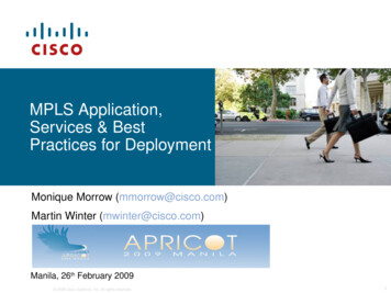
MP-BGP in the wildRoute TargetLabel Stack:advertises theVPN labelVPN-IP addr
summary
low configuration and maintenance costs CE - customer edge routers– don't need any special configuration; connected to aPE router via IP (e.g. with a point-to-point connection) PE - provider edge routers– simple configuration that depends only on the sites ofthe VPN’s that are adjaceny to the PE P – provider routers– simple configuration that does not depend on thedeployed VPN’s
forwarding efficiency PEs and Ps forward packet only depending on thelabels, that, in turn, depend only on theloopbacks of the PEs the forwarding tables in the backbone containonly one entry for each loopback much less than one entry for each customerprefix label switching lookup uses exact matching whileIP lookup uses longest prefix match
qos exploit traffic class field for enforcing QoS– tos field of packets is encapsulated inside theMPLS envelope and hence is not accessible whilethe packet is traversing the backbone– tos field is copied in the qos bits of MPLS label(named EXP bits) at the PE
traffic engineering LDP does not support traffic engineering one may use Resource Reservation Protocolwith Traffic Engineering (RSVP-TE)– more complex protocol, with more overhead,which includes support for traffic-engineering vianetwork resource reservations
internet many customers will also require Internet accessas well as VPN access more than one way to make this work (rfc4364)– CE announces 0/0 to PE works even if the customer has another ISP for Internet– Internet packets are forwarded natively (i.e., noMPLS)– PEs leak Internet routes in each VRF a possible alternative– 0/0 is associated with a specific RT, VPNs needingInternet access import it
caveats
MTU careful with the MTU inside the backbone– each MPLS label takes 4 bytes– risk of fragmentation high impact on performance IEEE 802.3 standard mandates support for one of– 1500 bytes MTU– 1504 bytes MTU (Q-tag)– 1982 bytes MTU (“envelope” frame) in practice, it is a matter of– implementation– hw support nowadays most OSes do PMTU discovery, so having anEthernet MTU of 1492 bytes (allowing 2 MPLS labels) is nota big issue– PPPoE also has a MTU of 1492 bytes – did you ever haveproblems?
TTL IP TTL field is encapsulated in an MPLS envelope,hence not accessible from LSRs– how do we prevent infinite loops in MPLS? recall MPLS label has its own TTL field– when the PE encapsulates the IP packet, it copies theTTL value in the newly added MPLS label– LSRs decrement the TTL in the label– when the label is popped, the TTL is copied onto thenext label– when the bottom-of-stack label is popped, the TTL iscopied onto the IP field
MPLS VPN l.cittadini, m.cola, g.di battista. motivations. customer's problem a customer (e.g., private company, public administration, etc.) has several geographically distributed sites and would like to connect them into a unique IP network - ideally it would like to have "wires"connecting its