Transcription
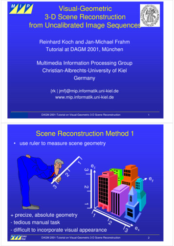
MIPVisual-Geometric3-D Scene Reconstructionfrom Uncalibrated Image SequencesMultimedia Information ProcessingReinhard Koch and Jan-Michael FrahmTutorial at DAGM 2001, MünchenMultimedia Information Processing GroupChristian-Albrechts-University of KielGermany{rk uni-kiel.deMIP CAUMultimedia Information ProcessingKielDAGM 2001-Tutorial on Visual-Geometric 3-D Scene Reconstruction1Scene Reconstruction Method 1 use ruler to measure scene geometry13ez223ey11 precize, absolute geometry2- tedious manual task- difficult to incorporate visual appearanceMIP CAUMultimedia Information ProcessingKielDAGM 2001-Tutorial on Visual-Geometric 3-D Scene Reconstruction3ex2
Scene Reconstruction Method 2 measure scene with camera, using image projections!ezey better to automate incorporate images for appearance- how can it be done ?MIP CAUMultimedia Information ProcessingKielDAGM 2001-Tutorial on Visual-Geometric 3-D Scene Reconstructionex3Goal of this tutorialComputer vision enables us to reconstruct highly naturalisticcomputer models of 3D enviroments from camera imagesWe may need to extract the camera geometry (calibration),scene structure (surface geometry) as well as the visualappearance (color and texture) of the sceneThis tutorial will––––MIP CAUMultimedia Information ProcessingKielintroduce the basic mathematical tools (projective geometry)derive models for cameras, image mappings, 3D structuregive examples for image-based panoramic modelingexplain geometric and visual models of 3D scene reconstructionDAGM 2001-Tutorial on Visual-Geometric 3-D Scene Reconstruction4
Outline of Tutorial1. Basics on affine and projective geometry2. Image mosaicing and panoramic reconstructionCoffee break3. 3-D scene reconstruction from multiple views4. Plenoptic modelingDemonstrations on mosaicing and 3-D modelingMIP CAUMultimedia Information ProcessingKielDAGM 2001-Tutorial on Visual-Geometric 3-D Scene Reconstruction6Part 1:Basics on affine and projective geometry Affine geometry– affine points and homogeneous coordinates– affine transformations Projective geometry– projective points and projective coordinates– projective transformations Pinhole camera model– Projection and sensor model– camera pose and calibration matrix Image mapping with planar homographiesMIP CAUMultimedia Information ProcessingKielDAGM 2001-Tutorial on Visual-Geometric 3-D Scene Reconstruction7
Affine coordinatesMei: affine basis vectorso: coordinate origine3GMa3Vector relative to o:GGGGM a1e1 a2e2 a3e3e2a2oe1a1Point in affine coordinates:G GGGG GM M o a1e1 a2e2 a3e3 oVector: relative to some originPoint: absolute coordinatesMIP CAUMultimedia Information ProcessingDAGM 2001-Tutorial on Visual-Geometric 3-D Scene ReconstructionKiel8Homogeneous coordinatesMUnified notation:include origin in affine basise3a3e2a2oa1Affine basis matrixMIP CAUMultimedia Information ProcessingKiele1G G G e1 e2 e3M 0 0 0HomogeneousCoordinates of M a1 Go a2 1 a3 1 DAGM 2001-Tutorial on Visual-Geometric 3-D Scene Reconstruction9
Euclidean coordinatesEuclidean coordinates: affine basis is orthonormal 0 GG e3 ez 0 1 0 G o 0 0 0 GG e2 ey 1 0 1 G G e1 ex 0 0 G G G e1 e2 e3Euclidean basis: 0 0 0MIP CAUMultimedia Information ProcessingKiel 1 for i keiT ek 0 for i k 1Go 0 1 0 00 0 0 1 0 0 0 1 0 0 0 1 DAGM 2001-Tutorial on Visual-Geometric 3-D Scene Reconstruction10Metric coordinatesMetric coordinates: affine basis is orthogonal 0 GG e3 ez 0 s 0 G o 0 0 0 GG e2 ey s 0 s G G e1 ex 0 0 G G G e1 e2 e3Metric basis: 0 0 0 MIP CAUMultimedia Information ProcessingKiel s for i k , s 0eTi ek 0 for i k 1G 0o s 01 0DAGM 2001-Tutorial on Visual-Geometric 3-D Scene Reconstruction0 0 0 1 0 0 0 1 0 0 0 1 11
Affine TransformationTransformation Taffine combines linear mapping andcoordinate shift in homogeneous coordinates– Linear mapping with A3x3 matrix– coordinate shift with t3 translation vectorMTaffineM’t3 A3 x 3M ′ TaffineM M 0 0 0 1 Linear mapping with A3x3:ot3MIP CAUMultimedia Information ProcessingKieloo’A3x3- Euclidean rigid rotation- metric isotropic scaling- affine skew and anisotropic scaling- preserves parallelism and length ratioDAGM 2001-Tutorial on Visual-Geometric 3-D Scene Reconstruction12Properties of affine transformationt3 A3 x 3′ M TaffineM M0001 Taffine a11 a12 aa 21 22 a31 a32 0 0a13a23a330tx ty tz 1 Parallelism is preserved ratios of length, area, and volume are preserved Transformations can be concatenated:if M1 T1M and M 2 T2M1 M 2 T2T1M T21MMIP CAUMultimedia Information ProcessingKielDAGM 2001-Tutorial on Visual-Geometric 3-D Scene Reconstruction13
Special transformation: RotationTRotation R3 x 3 0 0 00 r11 r120 r21 r22 0 r31 r32 1 0 0r13r23r3300 0 0 1 Rigid transformation: Angles and length preserved R is orthonormal matrix defined by three angles aroundthree coordinate axesezeyαexMIP CAUMultimedia Information Processing cos α Rz sinα 0 sinα 0 cosα 0 01 Rotation with angle α around ezDAGM 2001-Tutorial on Visual-Geometric 3-D Scene ReconstructionKiel15Special transformation: Rotation Rotation around the coordinate axes can be concatenated:ezeyαβγexR Rz R y R xInverse of rotation matrix: 1R RMIP CAUMultimedia Information ProcessingKielT0 1 Rx 0 cos γ 0 sin γ0 sin γ cos γ cos β Ry 0 sin β0 sin β 10 0 cos β cos α Rz sinα 0 sinα 0 cosα 0 01 DAGM 2001-Tutorial on Visual-Geometric 3-D Scene Reconstruction16
Projective geometry Projective space (3 is space of rays emerging from O– view point O forms projection center for all rays– rays v emerge from viewpoint into scene– ray g is called projective point, defined as scaled v: g λvw(3 x′ v y ′ 1 vyOMIP CAUMultimedia Information Processing x g (λ ) y λv , λ ℜ 0 w xDAGM 2001-Tutorial on Visual-Geometric 3-D Scene ReconstructionKiel17Projective and homogeneous points Given: Plane Π in *2 embedded in (3 at coordinates w 1– viewing ray g intersects plane at v (homogeneous coordinates)– all points on ray g project onto the same homogeneous point v– projection of g onto Π is defined by scaling v g/λ g/wwΠ(*2)w 1 x′ x g (λ ) λv λ y ′ y 1 w (3vyOMIP CAUMultimedia Information ProcessingKielxDAGM 2001-Tutorial on Visual-Geometric 3-D Scene Reconstruction x w x′ y1 v y ′ g w w 1 1 18
Finite and infinite points All rays g that are not parallel to Π intersect at an affine point v on Π. The ray g(w 0) does not intersect Π. Hence v is not an affine pointbut a direction. Directions have the coordinates (x,y,z,0)T Projective space combines affine space with infinite points (directions).g(3Π(*2)w 1g1g2vv1v2OMIP CAUMultimedia Information ProcessingKielDAGM 2001-Tutorial on Visual-Geometric 3-D Scene Reconstructionv x g y 0 19Relation between affine and projective points Affine space is embedded into projective space (x,y,z,w)T ashyperplane Π (x,y,z,1)T. Homogeneous coordinates map a projective point onto the affinehyperplane by scaling to w 1. Projective points with w 0 are projected onto Π by scaling with 1/w. Projective points with w 0 form the infinite hyperplane Π (x,y,z,0)T.They are not part of Π.MIP CAUMultimedia Information ProcessingKielDAGM 2001-Tutorial on Visual-Geometric 3-D Scene Reconstruction20
Affine and projective transformations Affine transformation leaves infinite points at infinity X ′ a11 a12 ′ Yaa 21 22 Z ′ a31 a32 0 0 0M ' TaffineM a13a23a330tx X t y Y tz Z 1 0 Projective transformations move infinite points into finite affine spaceM ' Tprojective M tx X a11 a12 a13 xp X ′ ′ aaatyY212223yp Y λ λ a31 a32 a33 zp Z′ tz Z 1 w ′ w 41 w 42 w 43 w 44 0 Example: Parallel lines intersect at the horizon (line of infinite points).We can see this intersection due to perspective projection!MIP CAUMultimedia Information ProcessingKielDAGM 2001-Tutorial on Visual-Geometric 3-D Scene Reconstruction21Pinhole Camera (Camera obscura)Interior of camera obscura(Sunday Magazine, 1838)Camera obscura(France, 1830)MIP CAUMultimedia Information ProcessingKielDAGM 2001-Tutorial on Visual-Geometric 3-D Scene Reconstruction22
Pinhole camera modelapertureView directionobjectimageMIP CAUMultimedia Information ProcessingDAGM 2001-Tutorial on Visual-Geometric 3-D Scene ReconstructionKiel23Pinhole camera modelImesgarsoneaperturernte )eC , cy(c xView directionobjectFocal length fimageMIP CAUMultimedia Information ProcessingKiellensDAGM 2001-Tutorial on Visual-Geometric 3-D Scene Reconstruction24
Perspective projection Perspective projection in (3 models pinhole camera:– scene geometry is affine *3 space with coordinates M (X,Y,Z,1)T– camera focal point in O (0,0,0,1)T, camera viewing direction along Z– image plane (x,y) in Π(*2) aligned with (X,Y) at Z Z0– Scene point M projects onto point Mp on plane surface X YM Z 1 Z (Optical axis)(3Z0Π(*2)yxImage planeMp X x p Z0ZX Y y Z0Y Zp0 M p ZZ0Z Z0 Z Z Z Z 11 Z0 YOCamera centerMIP CAUMultimedia Information ProcessingXDAGM 2001-Tutorial on Visual-Geometric 3-D Scene ReconstructionKiel25Projective Transformation Projective Transformation maps M onto Mp in *3 spaceρMpYOXM xp X 1 0yYρ M p TpM ρ p Z0 Z 0 0 1 W ρ 0 X 0 Y 1 0 Z 10z0 1 0 01 000Z projective scale factorZ0 Projective Transformation linearizes projectionMIP CAUMultimedia Information ProcessingKielDAGM 2001-Tutorial on Visual-Geometric 3-D Scene Reconstruction26
Perspective ProjectionDimension reduction from *3 into *2 by projection onto Π(*2)M xp 11 x p 0y y p 0 Z0p 0 1 0 1 0mpΠ (*2)YO001100000001000 xp 0 0 y p 0 mp DpM p0 Z0 1 1 1 XPerspective projection P0 from *3 onto *2: x 1 0 0 ρ mp DpTpM P0M ρ y 0 1 0 1 0 0 z10 MIP CAUMultimedia Information ProcessingKiel X 0 YZ0 , ρ Z Z00 1 DAGM 2001-Tutorial on Visual-Geometric 3-D Scene Reconstruction27Projection in general posePRotationmp[RProjection center C RTcam T 0]Projection: ρ mp PMMC 1 1camTscene TP0 RT T 0 RT C 1 World coordinatesMIP CAUMultimedia Information ProcessingKielDAGM 2001-Tutorial on Visual-Geometric 3-D Scene Reconstruction28
Image plane and image sensor A sensor with picture elements (Pixel) is added onto the image planePixel coordinatesm (y,x)TyxPixel scalef (fx,fy)TZ (Optical axis)Image centerc (cx, cy)TImage sensorFocal length Z0YXImage-sensor mapping:m KmpProjection center Pixel coordinates are related to image coordinates by affinetransformation K with five parameters: fx s c x K 0 fy c y – Image center c at optical axis 0 0 1 – distance Zp (focal length) and Pixel size scales pixel resolution f– image skew s to model angle between pixel rows and columnsMIP CAUMultimedia Information ProcessingKielDAGM 2001-Tutorial on Visual-Geometric 3-D Scene Reconstruction29Projection matrix P Camera projection matrix P combines:– inverse affine transformation Ta-1 from general pose to origin– Perspective projection P0 to image plane at Z0 1– affine mapping K from image to sensor coordinatesscene pose transformation: Tscene 1 0 0 0 projection: P0 0 1 0 0 [I 0] 0 0 1 0 R T T 0 RT C 1 fx s c x sensor calibration: K 0 fy c y 0 0 1 ρ m PM, P KP0Tscene K RTMIP CAUMultimedia Information ProcessingKielDAGM 2001-Tutorial on Visual-Geometric 3-D Scene Reconstruction RT C 30
The planar homography H The 2D projective transformation Hik is a planar homography– maps any point on plane i to corresponding point on plane k– defined up to scale (8 independent parameters)– defined by 4 corresponding points on the planes with not more thanany 2 points collinearplane kmk Hik mimkH ikplane imiMIP CAUMultimedia Information Processing h1Hik h4 h7h2h5h8DAGM 2001-Tutorial on Visual-Geometric 3-D Scene ReconstructionKielh3 h6 1 31Estimation of H from image correspondences Hik can be estimated linearily from corresponding point pairs:– select 4 corresponding point pairs, if known noise-free– select N 4 corresponding point pairs, if correspondences are noisy– compute H such that correspondence error f is minimizedProjective mapping: xk h1xi h2 y i h3 mk ρk y k Hmi h4 xi h5 y i h6 w h7 xi h8 y i 1 Error functional f:Nf ( mk ,n Hik mi ,n )2 min!n 0MIP CAUMultimedia Information ProcessingKielImage coordinate mapping:xk h1xi h2 y i h3h7 xi h8 y i 1yk h4 xi h5 y i h6h7 xi h8 y i 1 h1 Hik h4 h7DAGM 2001-Tutorial on Visual-Geometric 3-D Scene Reconstructionh2h5h8h3 h6 1 32
Image mapping with homographies Homographies are 2D projective transformations H3x3 Homographies map points between planes 2D homographies can be used to map images betweendifferent camera views for three equivalent cases:– (a) all cameras share the same view point Ci C, or– (b) all scene points are at (or near to) infinity, or– (c) the observed scene is planar. The 2D homography is independent of 3D scene structure!MIP CAUMultimedia Information ProcessingKielDAGM 2001-Tutorial on Visual-Geometric 3-D Scene Reconstruction33(a) Image mapping for single view point Camera with fixed projection center: Ci C Camera rotates freely with Ri and changing calibration KiGMC [I X Cx C ]M Y CY Z CZ ρ i mi Pi M K i RiTMρkmkmiρi RiT Ci MGTT K i Ri [I C ]M K i Ri MCGTTρk mk K k Rk [I C ]M K k Rk MCG MC Ri K i 1ρ i mi Rk K k 1ρ k mkρ k mk K k Rk 1Ri K i 1ρ i mi ρ i Hik miYCX Hik is a planar projective 3x3 transformation that mapspoints mi on plane i to points mk on plane kMIP CAUMultimedia Information ProcessingKielDAGM 2001-Tutorial on Visual-Geometric 3-D Scene Reconstruction34
(b) Image mapping for infinite scene with M All scene points are at or near infinity: M are points on Π Camera rotates freely with Ri and changing calibration KiM X 0 Ci ]M Y 0 Z 0 GM [IM mkmiYCiXCkGM Ri K i 1ρ i mi Rk K k 1ρ k mkMIP CAUMultimedia Information ProcessingKiel ρ k mk K k Rk 1Ri K i 1ρ i mi ρ i Hik miDAGM 2001-Tutorial on Visual-Geometric 3-D Scene Reconstruction35(c) Image mapping of planar scene ΠM All scene points are at on plane ΠM Camera is completely free in K,R,CMHiMΠMH kMH ikmkmiYCiXTransfer between images i,k over ΠM:MIP CAUMultimedia Information ProcessingKielCk 1Hik HiM H kMDAGM 2001-Tutorial on Visual-Geometric 3-D Scene Reconstruction36
Part 2:Mosaicing and Panoramic Images why mosaicing? geometries constraints for mosaicing mosaicing projective mainfolds stereo mosaicingMIP CAUMultimedia Information ProcessingKielDAGM 2001-Tutorial on Visual-Geometric 3-D Scene Reconstruction37Why mosaicing? cameras field of view is always smaller thanhuman field of view large objects can‘t be captured in a single pictureSolutions devices with wide field of view- fish-eye lenses (distortions, decreases quality)- hyper- and parabolic optical devices (lowerresolution) image mosaicingMIP CAUMultimedia Information ProcessingKielDAGM 2001-Tutorial on Visual-Geometric 3-D Scene Reconstruction38
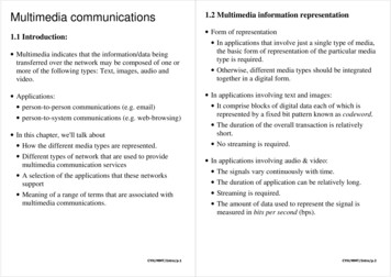
What is mosaicing?definition of mosaicing : Matching multipleimages by aligning and pasting images to awilder field of view image. Features that continueover the images must be "zipped" together, andthe frame edges dissolved.mosaicingKang et. al. (ICPR 2000)MIP CAUMultimedia Information ProcessingKielDAGM 2001-Tutorial on Visual-Geometric 3-D Scene Reconstruction39Geometries of mosaic aquisitionarbitrary sceneplanar scenerotatingcameraMIP CAUMultimedia Information ProcessingKieltranslating and rotatingcameraDAGM 2001-Tutorial on Visual-Geometric 3-D Scene Reconstruction40
Steps of mosaicingM Image alignment: estimation of homography Hfor each image pair Image cut and paste: selection of colorvaluefor each mosaic pixel Image blending: overcome of intensitydifferences between imagesIP CAUMultimedia Information ProcessingDAGM 2001-Tutorial on Visual-Geometric 3-D Scene ReconstructionKiel41Foreward mapping to planeMpixel to direction(P0Tscene ) 1mM 1scene 1m TKNmp M mp I 1 0T K m direction to mosaicρ mM K mosaic P0Tmosaic M IT 0usually Tmosaic C0 , K mosaic K 1 T 1Km ρ mM KR HMIP CAUMultimedia Information ProcessingKielDAGM 2001-Tutorial on Visual-Geometric 3-D Scene Reconstruction42
Forward mapping to planeMIP CAUMultimedia Information ProcessingDAGM 2001-Tutorial on Visual-Geometric 3-D Scene ReconstructionKiel43Forward mapping to spherepixel to directionMA0(P0Tscene ) 1mM M mp I 1 1 1m KTNscene T K mmp 0 direction to polar X ϕ tan Z 1ϕ Yϑ tan 22 X Z 1CMIP CAUMultimedia Information ProcessingKielDAGM 2001-Tutorial on Visual-Geometric 3-D Scene Reconstruction44
Planar scene mappingpixel to directionM(P0Tscene ) 1mM 1sceneKm TN 1mp M I 1 0T K m direction to mosaicmpρ mM K mosaic P0Tmosaic M usually TmosaicCMIP CAUMultimedia Information ProcessingKiel I T 00 , K mosaic K 1 ρ mM KP0 RT RT C P0 1K 1mDAGM 2001-Tutorial on Visual-Geometric 3-D Scene Reconstruction45Backward mapping from planeMmosaic to direction 1M (P0Tmosaic ) Km mosaic M 1mMM,pm 1mosaic T I 1 0T K mM mM , pdirection to pixelρ m KP0TsceneM C usually Tmosaic I T 00 , K mosaic K 1 1 ρ m KRKmM H 1MIP CAUMultimedia Information ProcessingKielDAGM 2001-Tutorial on Visual-Geometric 3-D Scene Reconstruction46
Backward mapping from planeMIP CAUMultimedia Information ProcessingKielDAGM 2001-Tutorial on Visual-Geometric 3-D Scene Reconstruction47mosaicsimage acquisition pure rotation around optical center planar scene translating and rotating cameraproblem ensure camera motion constaintsmosaic demoLive-Demonstration of Quicktime-VR Rotation-PanoramaNeo-Gothic Building (Leuven, Belgium)Rudy Knoops, AVD, K.U. LeuvenMIP CAUMultimedia Information ProcessingKielDAGM 2001-Tutorial on Visual-Geometric 3-D Scene Reconstruction48
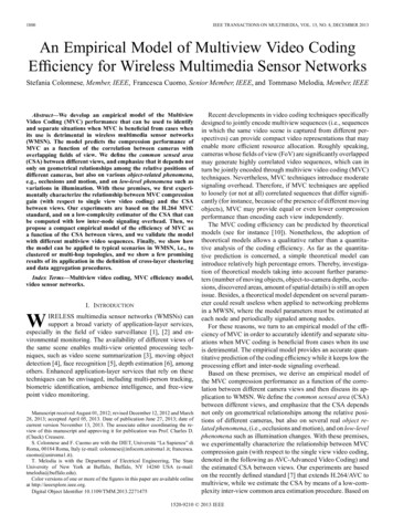
Manifold projection simulating sampling of scene with a 1-dim. sensorarray sensor can arbitrary translated and rotated inarbitrary scenesMIP CAUMultimedia Information ProcessingKielDAGM 2001-Tutorial on Visual-Geometric 3-D Scene Reconstruction49Manifold projectionplanar scenerotatingcamerapure translatingcamerarotating and translating cameraMIP CAUMultimedia Information ProcessingKielDAGM 2001-Tutorial on Visual-Geometric 3-D Scene Reconstruction50
Mosaic from stripsInIn-1In 1 stripes F(x,y) 0 perpendicular to optical flow F F normal , x y Tof stripe is parallel to optical flow select stripe as close as possible to image centerMIP CAUMultimedia Information ProcessingKielDAGM 2001-Tutorial on Visual-Geometric 3-D Scene Reconstruction51Manifold projection overcomes some of the difficulties of mosaicingdefined for any camera motion and scene structureresolution is the same as image resolutionsimplified computation (real time)visually good resultsProblem No metric in mosaic Life-Demonstration VideoBrushMIP CAUMultimedia Information ProcessingKielDAGM 2001-Tutorial on Visual-Geometric 3-D Scene Reconstruction53
Stereo mosaics multiple viewpoint panorama for each eye a seperate multiple viewpointpanorama constructed from one rotating cameraMIP CAUMultimedia Information ProcessingKielDAGM 2001-Tutorial on Visual-Geometric 3-D Scene Reconstruction54Stereo perceptionright eyerotatingheadcircular projectionleft eyeimage planeMIP CAUMultimedia Information ProcessingKielDAGM 2001-Tutorial on Visual-Geometric 3-D Scene Reconstruction55
The cameraCmosaicingCslitimage planeCrotationabout AslitCAAMIP CAUMultimedia Information ProcessingKielDAGM 2001-Tutorial on Visual-Geometric 3-D Scene Reconstruction56Using video camera rotate videocamera in the same way as split camera use two vertical image strips inplace of splitsCAMIP CAUMultimedia Information ProcessingKielDAGM 2001-Tutorial on Visual-Geometric 3-D Scene Reconstruction57
Stereo panoramaS. Peleg (CVPR 99)S. Peleg (CVPR 99)Ommnistereo demo OmniStereo Cooporation, 2000MIP CAUMultimedia Information ProcessingKielDAGM 2001-Tutorial on Visual-Geometric 3-D Scene Reconstruction58Part 3:3-D scene reconstruction from multiple views MIProjective and metric reconstruction2-view epipolar constraintcamera tracking from multiple viewsstereoscopic depth estimation3-D surface modeling from multiple viewsP CAUMultimedia Information ProcessingKielDAGM 2001-Tutorial on Visual-Geometric 3-D Scene Reconstruction59
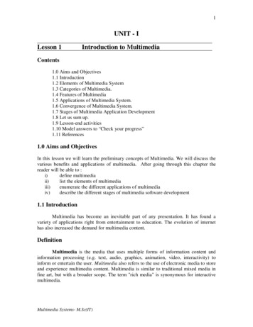
Scene reconstruction with projective cameras Calibrated Camera: K known, Pose (R,C) unknown (metric camera )P K [RT RT C ] Uncalibrated camera: K,R,C unknown (projective camera )P [KRT KRT C ] [B a]Reconstruction from multiple projective cameras: unknown: Scene points M, projection matrices P known: image projections mi of scene points Mi problem: reconstruction is ambiguous in projective space!-1 m i PM i P (T T )M i (PT -1 )(TM i ) PMi scene is defined only up to a projective Transformation T camera is skewed by inverse Transformation T-1MIP CAUMultimedia Information ProcessingKielDAGM 2001-Tutorial on Visual-Geometric 3-D Scene Reconstruction60Ambiguity in projective ionValid projective reconstructionsMIP CAUMultimedia Information ProcessingKielDAGM 2001-Tutorial on Visual-Geometric 3-D Scene Reconstruction61
Self-Calibration Recover metric structure from projective reconstruction Use constraints on the calibration matrix K Utilize invariants in the scene to estimate KApply self-calibration to recover T-1T-1Projective reconstructionMIP CAUMultimedia Information ProcessingKielMetric reconstructionDAGM 2001-Tutorial on Visual-Geometric 3-D Scene Reconstruction62Camera Self-Calibration from H Estimation of H between image pairs gives completeprojective mapping (8 parameter). Problem: How to compute camera projection matrix from H– since K is unknown, we can not compute R– H does not use constraints on the camera(constancy of K or some parameters of K) Solution: self-calibration of camera calibration matrix Kfrom image correspondences with H imposing constraints on K may improve calibrationInterpretation of H for metric camera:MIP CAUMultimedia Information ProcessingKiel h1 H h4 h7DAGM 2001-Tutorial on Visual-Geometric 3-D Scene Reconstructionh2h5h8h3 h6 K k Rk 1Ri K i 11 63
Self-calibration of K from H Imposing structure on H can give a complete calibrationfrom an image pair for constant calibration matrix Khomography Hik K k Rk 1Ri K i 1relative rotation: Rk 1Ri Rik , constant camera: K i K k KHik KRik K 1 Rik K 1Hik Ksince Rik 1 RikT Rik Rik T Rik K 1Hik K K T Hik T K T KK T Hik (KK T )HikT Solve for elements of (KKT) from this linear equation, independent of R decompose (KKT) to find K with Choleski factorisation 1 additional constraint needed (e.g. s 0) (Hartley, 94)MIP CAUMultimedia Information ProcessingKielDAGM 2001-Tutorial on Visual-Geometric 3-D Scene Reconstruction64Self-calibration for varying K Solution for varying calibration matrix K possible, if– at least 1 constraint from K is known (s 0)– a sequence of n image homographies H0i exist Rik K 0 1H0 i K i K 0T H0 iT K i Thomography H0 i K 0R0 1Ri K i 1 K i K iT H0 i (K 0K 0T )H0Tin 1solve by minimizing constraint K i K iT H0 i (K 0K 0T )H0Ti2 min!i 1 Solve for varying K (e.g. Zoom) from this equation, independent of R 1 additional constraint needed (e.g. s 0) different constraints on Ki can be incorporated (Agapito et. al., 01)MIP CAUMultimedia Information ProcessingKielDAGM 2001-Tutorial on Visual-Geometric 3-D Scene Reconstruction65
Multiple view geometryProjection onto two views:P0 K 0R0 1 [I 0]P1 K1R1 1 [Iρ0 m0 P0M K 0R0 1 [I 0]Mρ1m1 P1M K1R1 1 [I C1 ]M ρ0 m0 K 0R0 1 [I 0]M K1R1 1 [I 0]M K1R1 1 [I ρ1m1 ρ0H m0 e1 ρ0M M H m 0Zm0m1YOP1e1XC1MIP CAUMultimedia Information ProcessingKiel C1 ]Oρ1m1 K1R1 1R0 K 0 1ρ0 m0 K1R1 1C1MP0 C1 ]Epipolar line X X 0 0 YYM M O Z Z 0 1 0 1 DAGM 2001-Tutorial on Visual-Geometric 3-D Scene Reconstruction66The Fundamental Matrix F The projective points e1 and (H m0) define a plane incamera 1 (epipolar plane !e) the epipolar plane intersect the image plane 1 in a line(epipolar line le) the corresponding point m1 lies on that line: m1Tle 0 If the points (e1),(m1),(H m0) are all collinear, then thecollinearity theorem applies:collinearity of m1, e1, H m0 m1T ([e1 ]x H m0 ) 0[ ]x cross operatorFundamental Matrix FF [e1 ]x H MIP CAUMultimedia Information ProcessingKielF3 x 3Epipolar constraintm1T Fm0 0DAGM 2001-Tutorial on Visual-Geometric 3-D Scene Reconstruction67
The Fundamental Matrix Fl1 Fm0m l 0T1 1m1T Fm0 0F [e]xHa Fundamental MatrixP0Lm0MMal1Epipolee1m1e1T F 0m1a Ham0P1MIP CAUMultimedia Information ProcessingDAGM 2001-Tutorial on Visual-Geometric 3-D Scene ReconstructionKiel68Estimation of F from image correspondences Given a set of corresponding points, solve linearily for the 9elements of F in projective coordinates since the epipolar constraint is homogeneous up to scale,only eight elements are independent since the operator [e]x and hence F have rank 2, F has only7 independent parameters (all epipolar lines intersect at e) each correspondence gives 1 collinearity constraint solve F with minimum of 7 correspondencesfor N 7 correspondences minimize distance point-line:m Fm0 i 0T1iMIP CAUMultimedia Information ProcessingKielN (mn 0T1,nFm0,n )2 min!DAGM 2001-Tutorial on Visual-Geometric 3-D Scene Reconstruction69
Estimation of P from F From F we can obtain a camera projection matrix pair:– Set P0 to identity– compute P1 from F (up to projective transformation)– reduce projective skew by initial estimate of K to obtain a quasieuclidean estimate (Pollefeys et.al., ‘98)– compute self-calibration to obtain metric K similar to self-calibrationfrom H (Pollefeys et.al, ‘99, Fusiello ‘00)Fundamental matrixm1T Fm0 0e1T F 0MIP CAUMultimedia Information Processing Projective cameraP0 [I 0]P1 [[e1 ]x F e1aT e]DAGM 2001-Tutorial on Visual-Geometric 3-D Scene ReconstructionKiel703D Feature Reconstruction corresponding point pair (m0, m1) is projected from3D feature point M M is reconstructed from by (m0, m1) triangulation M has minimum distance of intersection2d min!P0m0l0m1FMIP CAUKielconstraints:dl0T d 0l1T d 0l1minimize reprojection error:P1Multimedia Information ProcessingM(m0 P0M) (m1 P1M)2DAGM 2001-Tutorial on Visual-Geometric 3-D Scene Reconstruction2 min.71
Multi View Tracking 2D match: Image correspondence (m1, mi) 3D match: Correspondence transfer (mi, M) via P1 3D Pose estimation of Pi with mi - Pi M min.P0Mm03D matchmim1P1NMinimize lobal reprojection error:K mi 0 k 0MIP CAUMultimedia Information ProcessingKielPi2D matchk ,i Pi Mk2 min!DAGM 2001-Tutorial on Visual-Geometric 3-D Scene Reconstruction72Structure from motion: an exampleImage SequenceMIP CAUMultimedia Information ProcessingKielDAGM 2001-Tutorial on Visual-Geometric 3-D Scene Reconstruction73
Extraction of image featuresm2Image 2m1Image 1 features m1,2 (Harris Cornerdetector) Select candidates based on cross correlation Test candidatesMIP CAUMultimedia Information ProcessingKielDAGM 2001-Tutorial on Visual-Geometric 3-D Scene Reconstruction74Robust selection of correspondencesRANSAC (RANdom Sampling Consensus)Hypothesis test: For N TrialsDO:– random selection of possible correspondences (minimum set)– compute F– test all correspondences [inliers/outliers]UNTIL ( Probability[#inliers, #Trials] 95%) Refine F with ML-estimateMIP CAUMultimedia Information ProcessingKielDAGM 2001-Tutorial on Visual-Geometric 3-D Scene Reconstruction75
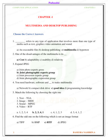
Estimation of Fundamental MatrixImage 2m 2T F m 1 0Image 1Robust correspondence selection m1 - m2MIP CAUMultimedia Information ProcessingKielDAGM 2001-Tutorial on Visual-Geometric 3-D Scene Reconstruction76Camera and feature trackingreconstruction of 3D features and camerasMIP CAUMultimedia Information ProcessingKielDAGM 2001-Tutorial on Visual-Geometric 3-D Scene Reconstruction77
3D surface modeling camera calibration from feature tracking dense depth estimation from stereo correspondence depth fusion and generation of textured 3D surface modelImage sequenceMIP CAUMultimedia Information ProcessingKielcamera calibrationscene geometry3D surface modelDAGM 2001-Tutorial on Visual-Geometric 3-D Scene Reconstruction78Dense depth estimation use of constraints along epipolar line (ordering, uniqueness) matching with normalized cross correlation fast matching in rectified image pairEpipolar line searchMIP CAUMultimedia Information ProcessingKielDAGM 2001-Tutorial on Visual-Geometric 3-D Scene Reconstruction79
Image rectification with planar mappingsmap between imagesestimate disparity Dmr Hr 1mr' Hr 1Dlr ml' Hr 1Dlr Hl ml 1 0 d Dlr (ml' , mr' ) 0 1 0 0 0 1 Mdepth ρ 1dM ρmr' Dlr ml''lmmr'dmlClMIP CAUMultimedia Information ProcessingKielHlHrmrCrDAGM 2001-Tutorial on Visual-Geometric 3-D Scene Reconstruction80Dense search for D use of constraints along epipolar line (ordering, uniqueness) matching with
DAGM 2001-Tutorial on Visual-Geometric 3-D Scene Reconstruction 6 MI P Multimedia Information Processing CAU Kiel Outline of Tutorial 1. Basics on affine and projective geometry 2. Image mosaicing and panoramic reconstruction Coffee break 3. 3-D scene reconstruction from multiple views 4. Plenoptic modeling Demonstrations on mosaicing and 3-D .