Transcription
Chapter 4: Programmable Logic Devices4.1Chapter OverviewThis Chapter provides an overview on Programmable Logic Devices (PLDs) formthe history of programmable logic devices to the device types. PLDs come in two forms,Complex Programmable Logic Devices (CPLDs) and Field Programmable Gate Arrays(FPGAs) both having their advantages and disadvantages with respect to the specificapplication or design they are to be used in. The PLD used for our design, which was aCPLD from Lattice Semiconductor is discussed. There is a need for design of smallermore dense electronic designs requiring less board space as well as less power in thespace and military industries there are very few PLD vendors that provide RadiationHardened components.Unfortunately intellectual Property Cores will be discussedwhich is the latest trend for vendors to provide system-on-a-chip capability for theirFPGA’s.4.2Introduction4.2.1Background of Programmable Logic DevicesA programmable Logic device refers to any type of integrated circuit that a logicdesign can be implemented and reconfigured in the field by the end user. Since theselogic devices can be programmed in the field they are also called Field ProgrammableLogic Devices (FPLDs). The PLD provides flexibility for designers to implement manydifferent designs in varying complexities for many different applications. One of themost common PLDs is the one time Programmable Read-only Memory (PROM). Thiscomes in two different types: (a) mask programmable devices programmed by the vendorusing a custom mask and interconnects and (b) field programmable devices that are16
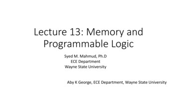
configured by the user.One of the great advantages of PLDs is that they are veryinexpensive at low quantities.A device that was a follow on from the PROM technology that can be used forlogic designs was the Programmable Logic Array (PLA). The PLA using the PROMstructure turned out to be the first Field Programmable Logic Array (FPLA). The firstFPLA was introduced in the mid-1970s. The FPLA had a fixed number of inputs,outputs and product terms that consisted of AND and OR arrays that containedprogrammable inputs. The FPLA did not have great success because they were very slowand complicated to use. The designer had to design to a fuse map instead of conventionalboolean equations or schematic capture.In the late 1970s the Programmable Array Logic (PAL) architecture wasintroduced that increased the use of programmable logic. The PAL architecture consistedof a programmable AND array and a fixed OR array so that each output is the sum of aspecific set of product terms. The design entry tool for the earlier PAL was in the formof Boolean equations making it very easy to learn and implement. PAL devices are nowavailable in different varieties from different vendors providing flexibility inputs/outputs,size of the OR-gate, and flip-flops. Some PALs are even provided in eitherNAND/NAND or NOR/NOR structure to increase design flexibility instead of theAND/OR structure.PLDs can be divided into two groups, Simple Programmable Logic Devices(SPLDs) and High-Density Programmable Logic Devices (HDPLDs). SPLDs come inthe PAL and PLA architecture, while HDPLDs include CPLDs and FPGAs. Figure 4.117
contains a hierarchical block diagram of the PLD architectures, subfamilies andprogramming technologies.ProgrammableLogicDevices (PLDs)SimpleProgrammableLogicDevices (SPLDs)High-DensityProgrammableLogic Devices(HDPLDs)ProgrammableLogic Array(PLA)ProgrammableArray ogrammableLogic leLogic gAntifuseProgrammingFigure 4.1 PLD Hierarchical Architecture4.2.2Simple Programmable Logic DevicesThe simple PAL architecture has become an industry standard. PLAs and PALsthat have pin packages of 20 – 44 pins and density ranging from 100 to several hundredgates are considered SPLDs. The Basic AND/OR architecture PALs are flexible devicesthat can implement logic equations in Boolean sum-of-product (SOP) form.Someenhancements to SPLDs have been programmable input/outputs (I/Os), bidirectionalI/Os, programmable output polarity, flexible register configurations and chip clocks.18
One important advantage for PLDs is that they can replace small to mediumscale integrated (SSI/MSI) circuits for higher packaging density. One PLD could replacetens of integrated circuits with 200 – 500 gate equivalent. Other benefits for SPLD is thatthey reduce power, have faster turn-around time, faster performance because they reduceinterconnects between chips and higher reliability. SPLDs are available in bipolar andComplementary Metal Oxide Semiconductor (CMOS) technology. In CMOS technology,they come in Erasable PROM (EPROM) based which are Ultraviolet Erasable(UVEPROM) and Electronically Erasable (EEPROM).Due to the simple architecture of an SPLD they offer very high performance. TheSPLD devices are at 0.5 um CMOS process with logic delays down to 3.5 ns andfrequencies as high as 200 MHz. Higher density devices are coming on the market in thearea of Complex Programmable Logic Devices (CPLD) with high performance, butSPLDs still have the best performance, easier to use and design with because they are anindustry standard.Computer networking components and other telecommunicationequipment still demand the need for SPLD devices due their high performance. Becauseof the trend to migrate to higher densities SPLDs have been driven to specialty marketssuch as cellular phones, video games and hand held web browsers.Table 4.1 shows acomparison of SPLDs and CPLDs over a broad range of criteria.New innovative advancements in SPLD include programmable output logic,macrocells that can be configured as combinatorial or register operation and active low oractive high polarity. SPLDs are also available in lower-voltage and low power offering 5volt and 3.3 volt devices. This allows more flexibility for design applications that requiretrade-offs between low power, high frequency and low voltage.19
CriteriaPropagation DelayDensitySPLDHigh Speed - Typically3.5 ns100 to Several HundredTechnologyEase of DesigningComplexityBipolar and CMOSVery EasySimple ArchitectureFrequencyProgrammable I/Os200 MHzYesCPLDHigh Speed - Typically10 nsSeveral Hundred to severalThousand (25,000 Gates)CMOSMedium EaseMedium to DifficultArchitecture100 MHzYesTable 4.1 SPLD and CPLD Comparison4.2.3High Density Programmable Logic DevicesThe main disadvantage for the SPLD is an architectural limitation. SPLDs have alimited amount of logic structures that can be allocated in a design in a fixed way. Highdensity or high-capacity PLDs (HDPLDs/HCPLDs), which are also called complexPLDs (CPLDs) and Field Programmable Gate Arrays (FPGAs), try to solve the siliconlimitation by adding more flexible block structures and interconnects. ProgrammableLogic Devices include simple as well as high-density PLDs.In 1985 Xilinx Corporation came out with the first FPGA. It introduced the LogicCell Array (LCA) and was the building block for all FPGAs to follow. It contained apool of independent logic cells and multiple routing resources that allowed any logic cellto be connected to any other logic cell. This provided routing flexibility. The first LCAconsisted of a combinatorial logic function and a flip-flop.The I/Os could beprogrammed as input, output and bi-directional and the routing resources allowed fordistributed clock through the chip, high speed and low-skew signals and local routingfrom LCA to LCA.20
The two major elements of CPLDs and FPGAs are the logic elements and theinterconnect structure. The logic elements are also known as macrocells, logic cellsand/or logic blocks. The interconnect structure is how those elements are connectedtogether to perform the design for a specific application. As mentioned there are twohigh-density programmable logic devices.Those are complex programmable logicdevices (CPLDs) and field programmable gate arrays (FPGAs). It is hard to determinethe difference between the two but usually in CPLDS there is fixed routing resources onchip and routing is done via a switching matrix, which leads to predictable delays. In theSPLD architecture, each macrocell contains its own product term. However, in theCPLD architecture the vendor takes advantage of the complex macrocells and employsproduct term steering or product term sharing between the macrocells. The term complexin CPLD refers to pin count and the amount of internal macrocells. The vendors try toprovide an output pin for each input set, which increases the complexity.One of the main performance criteria for PLDs is Total propagation delay (Tpd),which is the delay from the input to the output pin through a specific function. OnSPLDs of 44 pins this value is fixed and predictable due to less complex designs and isaveraged to be about 5 ns. When there is a larger and more complex design the Tpd canbe as high as 7.5 ns on devices that have 100 pins and 128 macrocells.In the past, there has not been a clear distinction between the roles of CPLDs andFPGAs until recently.A CPLD used to be higher priced and as mentioned havepredictable timing specifications making them ideal for high-speed applications. FPGAswhere more reasonably priced and satisfied the requirements for low to medium endperformance applications. FPGAs have found a niche for space and military applications21
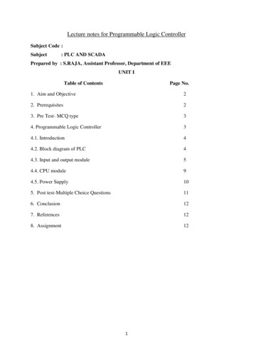
due to the availability of radiation Hardened devices. This will be discussed later in thechapter. Recently, CPLDs have been reduced in cost and have added additional featuressuch as in-circuit programmability and higher gate count. They tend to lend themselvestoward high-speed applications; real time video processing and Digital Signal Processing(DSP). The CPLDs used for this design cost 50.00 a unit making them attractive for atight budget. Both CPLDs and FPGAs are available in SRAM based programmingconfiguration but only CPLDs can be EPROM or EEPROM programmed. This meansthat CPLDs can be up and running when power is applied and are nonvolatile.SomeFPGAs are antifuse-based allowing them to only be one time programmable devices(OTPs) and SRAM based, which can be programmed as many times as required.High-density PLDs come in two basic architectures.Figure 4.2 shows theconnectivity differences between the two architectures. They are segmented-block basedand channel-array-based. Segmented-block architecture consists of a series of logicarrays and I/O macrocells that are connected together with an interconnect matrix. CPLDExamples of these are Advanced Micro Devices/Vantis MACH family and AlteraCorporation’s MAX family of devices. Segmented-block FPGAs have different means ofimplementing logic functions. One way is through the use of SRAM based Look-uptables (LUTs) and the other is through multiplexer-based logic elements that are typicallyin antifused-based devices like Actel Corporation’s ACT1, ACT2 and ACT3. Antifusebased FPGAs have less resistance than SRAM based, which decreases delay times, butare non-reprogrammable.Nonsegmented-block or channel-array-based contain inputpins connected to logic array elements that have interconnect paths to macrocells whichin-turn are connected to the I/O pins. Some examples of channel-array-based FPGAs are22
Xilinx Corporation Logic Cell Array (LCA), Atmel’s 6000 series and Lucenttechnologies’ ORCA series. Channel-array-based devices are register rich, have manyI/Os and have programmable interconnects between the logic elements and the I/Oblocks. The SRAM based devices are more resistive than the antifuse-based and aretypically slower.4 Input MacroCellInput oCellI/OPinsNonsegmentedFigure 4.2 Architectural Comparison Between Segmented and NonsegmentedThere has always been a debate over when to use a FPGA and when to use aCPLD. CPLDs are ideal for control circuits and state-machine based control logic. Theyhave fast, predictable timing. It is very difficult to predict the data path delays in a FPGA.The greatest advantage to FPGAs is having finer logic blocks and a very flexiblearchitecture for implementation in control logic designs, data path designs, arithmetic andlogic functions as well as register rich designs.23
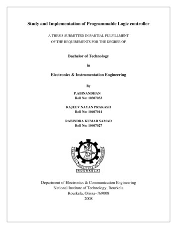
4.3Simple and Complex Programmable Logic Devices4.3.1Detailed ArchitectureLow density PLDs consist of PAL or PLA structures. These structures can be inthe form of AND-OR, NAND-NAND or NOR-NOR in multi levels of logic with I/Omacrocells and I/O pins. Figure 4.3 shows a portion of a simple PAL architecture. Thefour most important elements of the PAL structure are as follows:1. The AND-plane provides the connections between the inputs and the AND gates orthe product terms that implement the logic functions or control logic.2. The OR-plane makes the connections between the AND-plane and the outputs. TheOR-plane defines the number of ORed outputs, the number of product terms peroutput, how the product terms are distributed over the outputs and the connections ofthe Ored outputs with the storage elements.3. The storage elements determine the structure of the outputs. The storage elements areflip-flops that can provide clocking or feedback into the logic. The outputs can beconfigured to be sequential or combinatorial and have active high or low pull upresistors. The storage elements can be configured as edge-triggered D-type, J-K, R-Sor T flip-flops, or transparent latches.4. The I/O pins can be configured as an input, output or bidirectional.SPLDs of today are ten times faster then the original PALs. The propagation delay ofPLDs is down to 3.5 ns and even faster for state-of-the-art versions. The delay is slowdue to the oxide-isolated submicron 0.35 um processes and the UVEPROM andEEPROM storage cells.24
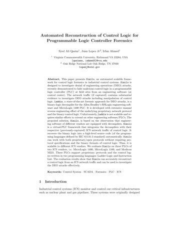
DCBOR Array(Fixed)AAND Array(Programmable)Q3Q2Q1Q0Figure 4.3 Simple PAL ArchitectureCPLDs consist of logic blocks, programmable interconnects, and I/O cells. Eachlogic block in the CPLD contains inputs, logic arrays and the array allocators, macrocells,and I/O cells. Figure 4.4 contains a generic block diagram of the CPLD architecture andfunctional description. The logic blocks perform sum of product logic function and storethe results in registers in the macrocells. The interconnections route signals to and fromthe logic and I/O cells to implement the desired logic design.The resources that are available in a CPLD are as follows:1. The number of macrocells is the amount of registers available to implement the logicfunction or the design to be implemented. The number of macrocells determines thecomplexity of the design.25
The Macrocell can beConfigured as Combinatorial orRegisteredLogic BlockClock / ellI/OCellsI/OPinsMacroCellInput PinsThe HighSpeed MatrixRoutes SignalsThroughout theDeviceThe Logic ArrayConsists ofProduct TermsThat Form theBasis of theLogic BeingImplementedThe AllocatorI/O CellsDistributesProvide aProduct TermsThree-statefor EfficientBufferLogicConfigurable asImplementation Input, OutputandBidirectionalFigure 4.4 CPLD Architectural Block Diagram2. The number of inputs to individual logic blocks is another important resource. If thedesign requires more inputs to a specific set of logic blocks than are available, thenmultiple logic blocks can be used to account for the lack of available inputs.3. The final resource is the total number and allocation of product terms. The totalnumber of product terms that the device can OR together defines the upper limit forthe amount of logic that can fit into the CPLD. Product term allocation is sometimesmore important than the total number of product terms. Some times the allocationfunction needs to feedback through multiple logic cells to implement the logicfunction at the expense of increased delay.Sometimes the allocation functionrequires that product terms be assigned to individual macrocells or product terms tobe assigned to multiple macrocells for product term steering and sharing respectively.26
The CPLD performance is dependent upon the interconnections between logic cellsfor which there are two different aspects as follows:1. The number of signals that the global interconnect provides to each logic celldetermine how well the CPLD will perform on a specific logic design. If the amountof input signal to the logic cells is smaller than the number that is required for thelogic function then it will have to be slit between multiple logic cells to account forthe lack of input signals.2. The second performance aspect is routability efficiency or how well the interconnectsignals get routed between the logic cells in the most efficient manner. When thenumber of signals that need to be routed reaches a maximum for the specific designand chip architecture, it becomes more difficult to route the signals.CPLDs consist of two types of interconnect structures.1. The first type is called the crosspoint switch architecture.This architecture iscompletely routable because any combination of signals can be routed from any logicblock via the global interconnect. The only problem with this architecture is that thevast amount of routing capability decreases the overall speed and increases the diesize.2. The multiplexer approach is used instead of the crosspoint switch to increase theoverall speed and to reduce the size of the chip. Figure 4.5 contains a block diagramof the multiplexer-based interconnect structure.Many vendors have differentapproaches to try to optimize the routability efficiency.CPLDs have a wide input structure and large sum of product arrays. They are idealfor implementing fast state machine designs, high speed control logic and fast decode27
applications. Many vendors have implemented the in-system programmability functionthat reduces on the chip handling and makes it flexible to change designs while the chipis mounted on the kI/OLogicBlockLogicBlockFigure 4.5 CPLD Multiplexer-Based Interconnect Structure4.3.2Programming TechnologiesThe programming technology of earlier PLDs was based on bipolar processes,which came from PROM technologies. The PROM structure contained lateral fuses andvertical fuses. The lateral fuses, or metal alloy, would interconnect two wires. When thelateral fuses are blown due to the current through a bipolar transistor, the two wires arenot connected. The vertical fuses did not have the metal alloy but they did have thebipolar transistors in series with back-to-back diodes. The diodes would isolate the twowires in the not blown state. Enough current through the transistor would cause an“avalanche effect” that would short one of the diodes connecting the two wires. Thefuses are made out of different materials like nichrome, titanium-tungsten and platinumsilicide.The fusible-link PLDs have different programming requirements that arespecified by the vendor in the data sheets.28
The programming technologies for CPLDs are UVEPROM and EEPROM. In theEEPROM and UVPROM CPLDs transistors are used as switches to make interconnectsjust as the fuses in the SPLDs. The programming technology is an important elementwhen selecting devices. The selection of a particular device also depends on volatility,nonvolatility, reprogrammability, in-system programmability (ISP), program time, erasetime and testability.The electrically erasable CMOS technology is based on a stored charge ona transistor with a “floating gate” or a gate that has no connection. There are actually twotransistors, one that has the floating gate and another that is the control gate. In theprogrammed state the transistor is turned on due to a positive charge caused by a deficitof electrons in the floating gate. Figure 4.6 shows the schematic for the electricallyerasable programming cell.Read LineProgram LineWord LineProgram TransistorRead TransistorElectron SourceTunnel OxideControl GateSense TransistorFloatingGateSourceFigure 4.6 Schematic of Electrically Erasable Programming Cell29
Hot electron injection and tunneling are the two ways of transferring a charge onto the floating gate.UVEPROM uses hot electron injection and EEPROM usestunneling. In hot electron injection a bias is set between the source and the drain of thetransistor of the control gate and the substrate. A strong current is present causing thechannel to be pinched off. A field is formed in the diagonal direction by two appliedelectrical fields. The electrons can not pass in that direction due to the oxide barrier.Some electrons have enough energy to cross the barrier at the shortest point over into thefloating gate where they are trapped. The term hot electron injection refers to the highelectron fields. During programming large electron fields are established to get a largeamount of electrons over the oxide barrier and over to the floating gate. Exposing thedevice to UV light will erase the device because it causes the electrons to cross back overthe barrier. The UVEPROM devices need a window to allow the UV light to enter thedevice. The special packaging of the device increases the cost and results in about 30 to45 minutes to erase the device. Figure 2.7 shows a schematic of hot-electron injection inUV-erasable devices.Electrically erasable devices use Fowler-Nordheim tunneling to get the electronover the barrier onto the floating gate. The electrons tunnel through the barrier when afield is applied. For electrically erasable parts the oxide barrier is about one-third thethickness as it is for UV parts, making the field much less to get the electrons across.EEPROM based devices are more cost effective than UVEPROM based devices.To improve the performance of electrically erasable PLDs, the programming cellhas been divided into two parts. One is the programming portion and the other is the datapath portion.The programming portion requires transistors that can handle high30
electrical fields and the data path portion requires transistors that are fast. A cell isprogrammed if it generated a negative voltage as a result of no charge on the floatinggate. Large amounts of charge on a floating gate caused by applying a negative voltagewill erase a cell. When a voltage is applied between the program and control gate nodes,the direction of that voltage determines if the device is getting programmed or erased. Ifthe control gate is given a positive voltage and the program node is grounded the deviceis being erased. The positive voltage draws electrons across the tunnel oxide form theprogram transistor to the floating gate, which turns the read transistor OFF.Forprogramming, the program node voltage is higher and the control gate is groundedcausing electrons to flow from the gate leaving behind a positive charge that turns thetransistor on.Control GateFloating GateHot Electron InjectionOxide BarrierFielde-eee-e-n sourcen drainFieldPinch-Off ChannelDepletion RegionP-substrateFigure 4.7 Schematic of Hot-Electron Injection31
4.3.3Simple and Complex Programmable Logic Devices SummaryThere are many different SPLD/CPLD vendor and their device families andarchitectures. The major SPLD/CPLD vendors and device families are AMD/Vantis withPAL and MACH families, Altera with MAX and FLEX families, Cypress SemiconductorEPLD/CPLD families, ICT Peel arrays family, Phillips Semiconductors’ CPLD familiesand Xilinx FastFlash CPLD family, just to name a few. Depending on the designrequirements and specifications, there are tradeoffs on selecting FPGA architectures overCPLD architectures. There are also tradeoffs in selecting a specific CPLD architecture tomeet the system requirements.The next section will cover the CPLD vendor andarchitecture chosen to implement the design. Lattice Semiconductor is the CPLD vendorwith high-density in-system programmable Large Scale Integrated (ispLSI) CPLDs. TheLattice CPLD architecture provides very flexible architecture with high-density logic.The Camera design implemented is for a research and development project with generalrequirements.The in-system programmable feature allowed for ease in designmodifications and debugging capability. The cost of the devices and the ElectronicDesign Automation tools to implement the design was reasonable for the budgetavailable. A very important feature is the predictable timing of a CPLD. The interfacedesign was a complex design done in VHDL.The predictable timing allowed forlearning the design and the code rather than the device architecture and timing issues.The Lattice devices also have a wide range of speed options, which meet therequirements of the design. The VHDL implementation of the design will be discussedin Chapter 6, VHDL Design Entities.32
4.3.4Lattice Semiconductor OverviewLattice Semiconductor CPLDs are nonvolatile EECMOS technology. There aresix families and they are 1000/1000E, 2000/2000V, 3000 and 6000. The densities rangefrom 1000 to 25,000 PLD gates. A very important feature of this architecture is theGlobal Routing Pool, which connects all the internal structures and I/O’s with predictabletiming. Another key element is the Generic Logic Blocks (GLB). They provide a highinput to output ratio for design optimization. The architecture also allows for a ProductTerm-Sharing Array (PTSA) and two types of clocking signals. The two clocks are anexternal globally distributed snychronous clock and an internal globally distributedasynchronous product term clock. The Output Routing Pool (ORP) allows for flexibleinterconnections between the GLBs and the I/O modules.4.3.4.1Lattice Semiconductor ispLSI 1000/EThe GLBs for the 1000/E contain 18 inputs, programmable AND/OR/XOR arrayand four outputs. The four outputs can be configured as combinatorial and registered.The difference in the 1000E is that it has two more global output enable pins and aprogrammable output slew rate control.The Global Routing Pool (GRP) is the internal routing structure that connects theGLBs to the I/Os and the I/Os to the GLBs. The output of any GLB is available for inputinto any other GLB. The I/O pins are also available to interconnect to any GLB input.The ORP is the routing structure in the architecture that allows the GLBs to be connectedto the I/Os. This allows flexibility when assigning I/O pins.A megablock consists ofeight GLBs and 16 I/O cells. The 1000E has two dedicated input signals that are commonto all GLBs and the product term OE which is common to all 16 I/Os. The densities in33
the 1000/E family range form 16 GLBs to 48 GLBs. Figure 4.8 contains a functionalblock diagram of one of the ispLSI 1000 devices.I/OI/OI/OI/O I/OI/OI/OI/O I/OI/OI/OI/O I/OI/OI/OI/OInput BusGenericLogic Blocks(GLB)INOutput Routing PoolInput BusOutput Routing PoolGLB GLB GLB GLB GLB GLB GLB GLBGLB GLB GLB GLB GLB GLB GLB GLBIN INI/O I/O I/O I/O I/O I/O I/O I/O I/O I/O I/O I/O I/O I/O I/O I/OClockNetworkInput BusOutput Routing PoolGLB GLB GLB GLB GLB GLB GLB GLBGlobalRoutingPool(GRP)INGLB GLB GLB GLB GLB GLB GLB GLBMegablockI/O I/O I/O I/O I/O I/O I/O I/O I/O I/O I/O I/O I/O I/O I/O I/OIN INCLK0CLK1IOCLK0IOCLK1Output Routing PoolInput BusY3 Y2 Y1 Y0I/O I/O I/O I/O I/O I/O I/O I/O I/O I/O I/O I/O I/O I/O I/O I/OIN INFigure4.8: isp LSI Functional Block DiagramA GLB is divided into four sections. The four sections are the AND array,Product-Term-Sharing Array (PTSA), reconfigurable registers and the control functions.The AND array in the PTSA consists of 20 product terms that has 18 inputs available toproduce a logic sum. 16 of the 18 inputs are from the GLP that can be connected to I/Osor any other GLB. The other two inputs are the dedicated inputs. The PTSA routes the20 product terms to the 4 GLB outputs. The OR gates have four, five, or seven productterm inputs to them. The OR gates can be routed to any GLB output. The PTSA allows34
for product term sharing or combining. The reconfigurable registers are XOR gate inputsto D-type flip-flops. The XOR gate can be used as a logic element or to configure theregister as a JK or T-type flip-flop. The registers can be bipassed if the design requirescombinatorial logic and is brought out to the GRP. The I/O signals are routed to theGRP. The I/O cell is used to route input, output and bidirectional signals connected tothe I/O. There are five global clocks for the devices. CLK0, CLK1 and CLK2 are forGLB clocking and IOCLK0 and IOCLK1 are for clocking the I/O cells.4.3.4.2Lattice Semiconductor ispLSI 2000/VThe ispLSI 2000 family has densities ranging from 32 macrocells up to 128macrocells, which is equivalent to 1000 PLD gates and 6000 PLD gates respectively.The 2000V device is a low voltage version of the 2000 at 3.3 V. The global logic block(GLB) for the 2000 family is essentially the same as for the 1000 family. Figure 2.9 isthe schematic of the generic logic block for the 2000 family. The general architecture hasthe following modifications and enhancements: GLB and clock multiplexer scheme is different on the 2000 series. There are threededicated clocks CLK0, CLK1 and CLK2. These clocks are used to clock all theGLBs that are configured as registers. The clocks are used inside the GLBs and areselected by a multiplexor. The internal clock signals are connected to the I/O pins Y0through Y2. The 2000/V family made a simplified I/O register. The I/O cell can be configured asan input, output and bidirectional with tri-state control. The I/O clocks were removedand the outputs can be configured as totem pole or open-drain.35
The Output Routing Pool (ORP) was enhanced for further routing capability. The2000 series devices have two sets of ORPs per megablock allowing all 32 outputs ofthe GLBs to have access to the 32 I/O cells. This architecture doubles the routabilityof this family.Inputs From GlobalRo
4.2.1 Background of Programmable Logic Devices A programmable Logic device refers to any type of integrated circuit that a logic design can be implemented and reconfigured in the field by the end user. Since these logic devices can be programmed in the field they are also called Field Programmable Logic Devices (FPLDs).