Transcription
Integrated Circuits (ICs)In the 1950s, transistors and other electronic components were availableonly in individual packages. These discrete components were laid out ona circuit board and hand connected using separate wires. At that time, anelectronic gate capable of storing a single binary bit of data cost more than 2.By comparison, in the early 1990s, enough gates to store 5,000 bits of data costless than a cent. This vast reduction in price was primarily due to the inventionof the integrated circuit (IC). 1A functional electronic circuit requires transistors, resistors, diodes, etc.and the connections between them. A monolithic integrated circuit (the"monolithic" qualifier is usually omitted) has all of these components formedon the surface layer of a sliver, or chip, of a single piece of semiconductor;hence the term monolithic, meaning "seamless." Although a variety of semiconductor materials are available, the most commonly used is silicon, andintegrated circuits are popularly known as "silicon chips." Unless otherwisenoted, the remainder of these discussions will assume integrated circuits basedon silicon as the semiconductor.An O v e r v i e w of the Fabrication ProcessThe construction of integrated circuits requires one of most exacting production processes ever developed. The environment must be at least a thousandtimes cleaner than that of an operating theater, and impurities in materialshave to be so low as to be measured in parts per billion, z The process beginswith the growing of a single crystal of pure silicon in the form of a cylinder witha diameter that can be anywhere up to 300 mm. 3 The cylinder is cut into paperthin slices called wafers, which are approximately 0.2 mm thick (Figure 14-1).1 In conversation, IC is pronounced by spelling it out as "I-C".2 If you took a bag of flour and added a grain of salt, this would be impure by comparison.3 This 300 mm value was true as of 2002. However, in 1995 (when the first edition of this tomehit the streets), the maximum diameter was 200 mm, so who knows what it will be in the future?
144 II C h a p t e r FourteenCylindrical siliconcrystalThe thickness ofthe wafer is determinedby the requirement for25 mm toWafersufficient mechanical3 0 0 mm0.2 mmstrength to allow it tobe handled withoutdamage. The actualFigure 14-1. Creating silicon wafersthickness necessaryfor the creation of theelectronic components is less than 10 gm (ten-millionths of a meter). After thewafers have been sliced from the cylinder, they are polished to a smoothnessrivaling the finest mirrors.The most commonly used fabrication process is optical lithography, in whichultraviolet light (UV) is passed through a stencil-like 4 object called a photomask, or just mask for short. This square or rectangular mask carries patternsformed by areas that are either transparent or opaque to ultraviolet frequencies(similar in concept to a black and white photographic negative) and the resulting image is projected onto the surface of the wafer. Bymeans of some technical wizardry that we'llconsider in the next section, we canUltravioletradiationuse the patterns of ultraviolet light toS O LI r o egrow corresponding structures in thesilicon. The simple patterns shown inthe following diagrams were selectedMaskIiifor reasons of clarity; in practice, aiEach squaremask can contain millions of finecorresl onds toan individuallines and geometric shapes (Figureintegratedcircuit14-2).Each wafer can contain hundredsor thousands of identical integratedcircuits. The pattern projected ontothe wafer's surface corresponds to aWafer.74Figure 14-2. The opto-lithographicstep-and-repeat process4The term "stencil" comes from the Middle Englishword stencelled,meaning "adorned brightly."
Integrated Circuits (ICs) 9145single integrated circuit, which is typically in the region of l mm x l mm to10mm x 10mm, but may be even larger. After the area corresponding to oneintegrated circuit has been exposed, the wafer is moved and the process isrepeated until the pattern has been replicated across the whole of the wafer'ssurface. This technique for duplicating the pattern is called a step-and-repeatprocess.As we shall see, multiple layers are required to construct the transistors(and other components), where each layer requires its own unique mask. Onceall of the transistors have been created, similar techniques are used to lay downthe tracking (wiring) layers that connect the transistors together.A M o r e Detailed Look at the Fabrication ProcessTo illustrate the manufacturing process in more detail, we will consider theconstruction of a single NMOS transistor occupying an area far smaller than aspeck of dust. For reasons of electronic stability, the majority of processes beginby lightly doping the entire wafer to form either N-type or, more commonly,P-type silicon. However, for thepurposes of this discussion, we willassume a process based on a puresilicon wafer (Figure 14-3).Assume that the small area ofsilicon shown here is sufficient toaccommodate a single transistorin the middle of one of theFigure 14-3. Small area in theintegrated circuits residing somemiddle of the silicon waferwhere on the wafer. During thefabrication process the wafer isoften referred to as the substrate,meaning "base layer." A commonfirst stage is to either grow ordeposit a thin layer of siliconSilldioxide (glass) across the entiresurface of the wafer by exposingSilicon (substrate)it to oxygen in a high-temperatureFigure 14-4. Grow or deposit aoven (Figure 14-4).!!clayer of silicon dioxide
146 [] C h a p t e r FourteenAfter the wafer hascooled, it is coated with athin layer of organic resist, 5which is first dried and thenbaked to form an imperviouslayer (Figure 14-5).A mask is created andOrganic resistultraviolet light is applied.SiliconSilicon dioxideThe ionizing ultraviolet(substrate)radiation passes through theFigure 14-5. Apply a layer of organic resisttransparent areas of themask into the resist, siliconUltravioletdioxide, and silicon. The ultraviolet breaksradiation sourcedown the molecular structure of the resist, butdoes not have any effect on the silicon dioxideor the pure silicon (Figure 14-6).As was previously noted, the small areaof the mask shown here is associated with asingle transistor. The full mask for an inte" Maskgrated circuit can consist ofmillions of similar patterns.After the area under themask has been exposed, thewafer is moved, and theprocess is repeated until thepattern has been replicatedacross the wafer's entireOrganic resistsurface, once for each integrated circuit. The wafer isSiliconSilicon dioxide(substrate)then bathed in an organicsolvent to dissolve theFigure 14-6. The exposed resist is degradedby the ultraviolet lightdegraded resist. Thus, the5 The term "organic" is used because this type of resist is a carbon-based compound, and carbonis the key element for life as we know it.
Integrated Circuits (ICs) 914 7pattern on the mask hasbeen transferred to a seriesof corresponding patterns inthe resist (Figure 14-7).A process in whichultraviolet light passingthrough the transparentareas of the mask causes theresist to be degraded isknown as a positive-resistprocess; negative-resistOrganic resistSilicon(substrate)Silicon dioxideFigure 14-7. The degraded resist is dissolvedwith an organic solventprocesses are also available.In a negative-resist process,the ultraviolet radiationpassing through the transparent areas of the mask isused to cure the resist, andthe remaining uncured areasare then removed using anappropriate solvent.Organic resistAfter the unwantedSiliconSilicon dioxideresist has been removed, the(substrate)wafer undergoes a processFigure 14-8. Etch the exposed silicon dioxideknown as etching, in whichan appropriate solvent isused to dissolve any exposed silicon dioxide without having any effect on theorganic resist or the pure silicon (Figure 14-8).The remaining resist is then removed using an appropriate solvent, and thewafer is placed in a high temperature oven where it is exposed to a gas containing the selected dopant (a P-type dopant in this case). The atoms in the gasdiffuse into the substrate resulting in a region of doped silicon (Figure 14-9). 66 In some processes, diffusion is augmented with ion implantation techniques, in which beams of ionsare directed at the wafer to alter the type and conductivity of the silicon in selected regions.
148 9 C h a p t e r FourteenGas containingP-type dopantThe remaining silicondioxide layer is removed/ /!by means of an appropriate solvent that doesn'taffect the silicon substrate (including thedoped regions). ThenP-1additional masks andSilicon dioxidevariations on the processSiliconare used to create two(substrate)N-type diffusion regions,Figure 14-9. Dope the exposed silicona gate electrode, and alayer of insulating silicon dioxide between thePoly-crystalline silicon(gate electrode)substrate and the gate electrode (Figure 14-10).In the original MOS technologies, thegate electrode was metallic: hence theN-typesilicon"metal-oxide semiconductor" appellation. In modern processes, however,Silicon diSiliconthe gate electrode is formed from poly(substrate).\N-t- ,Figure 14-10. Add n-type diffusionregions and the gate electrodecrystalline silicon (often abbreviated topolysilicon or even just poly), which isalso a good conductor.The N-type diffusions form thetransistor's source and drain regions (you might wish to refer back to Figure 4-9ain Chapter 4 to refresh your memory at this point). The gap between the sourceand drain is called the channel. To provide a sense of scale, the length of thechannel may be in the order of 0.1 btrn (one-tenth of one-millionth of a meter),and the thickness of the silicon dioxide layer between the gate electrode andthe substrate may be in the order of 0.05 pin (see also the discussions on devicegeometries later in this chapter).Another layer of insulating silicon dioxide is now grown or deposited acrossthe surface of the wafer. Using similar lithographic techniques to those describedabove, holes are etched through the silicon dioxide in areas in which it isdesired to make connections, and a metalization layer of aluminum interconnections (think of them as wires) called tracks is deposited (Figure 14-11 ).
Integrated Circuits (ICs) 9 149Metal trackThe end result is anMetal track(drain)(gate)NMOS transistor; a logic 1on the track connected toInsulating layerthe gate will turn theof silicon dioxideMetal tracktransistor ON, therebySilicon (substrate)(source)enabling current to flowbetween its source and drainterminals. An equivalentPMOS transistor could havebeen formed by exchanging theFigure 14-11. Add themetalization (tracks)P-type and N-type diffusionregions. By varying the structurescreated by the masks, components such as resistors and diodes can be fabricatedat the same time as the transistors. The tracks are used to connect groups oftransistors to form primitive logic gates and to connect groups of these gates toform more complex functions.An integrated circuit contains three distinct levels of conducting material:the diffusion layer at the bottom, the polysilicon layers in the middle, and themetalization layers at the top. In addition to forming components, the diffusionlayer may also be used to create embedded wires. Similarly, in addition toforming gate electrodes, the polysilicon may also be used to interconnectcomponents. There may be several layers of polysilicon and several layers ofmetalization, with each pair of adjacent layers separated by an insulating layerof silicon dioxide. The layers of silicon dioxide are selectively etched with holesknown as vias, which allow connections to be made between the varioustracking layers.Early integrated circuits typically supported only two layers of metalization.The tracks on the first layer predominantly ran in a "North-South" direction,while the tracks on the second predominantly ran "East-West. ''7 As the number7 In 2001, a group of companies announced a new chip interconnect concept called X Architecture(www.xinitiative.org) in which logic functions on chips are wired together using diagonal tracks(as opposed to traditional North-South and East-West tracking layers). Initial evaluationsapparently show that this diagonal interconnect strategy can increase chip performance by 10%and reduce power consumption by 20%. However, it may take awhile before design tools andprocesses catch u p . . . watch this space?
150 9 C h a p t e r Fourteeniof transistors increased, engineers required more and more tracking layers.The problem is that when a layer of insulating silicon dioxide is depositedover a tracking layer, you end up with slight "bumps" where the tracks are(like snow falling over a snoozing polar b e a r y o u end up with a bump).After a few tracking layers, the bumps are pronounced enough that youcan't continue. The answer is to re-planarize the wafer (smooth the bumps out)after each tracking and silicon dioxide layer combo has been created. This isachieved by means of a process called chemical mechanical polishing (CMP),which returns the wafer to a smooth, flat surface before the next tracking layeris added. With manufacturers using this process, high-end silicon chips couldsupport up to eight tracking layers by 2002.Relatively large areas of aluminum called pads are constructed at the edgesof each integrated circuit for testing and connection purposes. Some of the padsare used to supply power to the device, while the rest are used to provide inputand output signals (Figure 14-12).The pads can be connected to the internal components using the diffusion,polysilicon, or metalization layers. In a step known as overglassing, the entiresurface of the wafer is coated with a final barrier layer (or passivation layer)of silicon dioxide or silicon nitride, which provides physical protection forthe underlying circuits from moisture and other contaminants. One morelithographic step is required to pattern holes in the barrier layer to allowconnections to be made to the pads. In some cases, additional metalizationmay be deposited on the pads to raise them fractionally above the level of thebarrier layer. Augmenting the pads in this way is known as silicon bumping.The entire fabrication process requires numerous lithographic steps, eachinvolving an individual maskand layer of resist to/ / selectively expose{ ./// "{ 7// different parts ofthe wafer. PadsFigure 14-12. Power and signal pads
Integrated Circuits (ICs) 9151The Packaging ProcessThe individual integrated circuits are tested while they are still part of thewafer in a process known as wafer probing. An automated tester places probes onthe device's pads, applies power to the power pads, injects a series of signalsinto the input pads, and monitors the corresponding signals returned from theoutput pads. Each integrated circuit is tested in turn, and any device that failsthe tests is automatically tagged with a splash of dye for subsequent rejection.The yield is the number of devices that pass thetests as a percentage of the total numberfabricated on that wafer.The completed circuits, known asdie, 8 are separated by marking the waferwith a diamond scribe and fracturing italong the scribed lines (much likecutting a sheet of glass or breaking up aKit Kat bar) (Figure 14-13).Following separation, the majority ofthe die are packaged individually. SinceFigure 14-1 3. Die separationthere are almost as many packaging technologies as there are device manufacturers,we will initially restrain ourselves to a relatively traditional process. First, thedie is attached to a metallic lead frame using an adhesive (Figure 14-14).Lead framee-,,Bare lead frameFigure 14-14. Die attached to lead frames The plural of die is also die (in much the same way that "a shoal of herring" is the plural of "herring").
152 9 C h a p t e r FourteenOne of the criteria used when selecting the adhesive is its ability to conductheat away from the die when the device is operating. A n automatic wire bondingtool connects the pads on the die to the leads on the lead frame with wirebonds finer than a human hair. 9 The whole assembly is then encapsulated in ablock of plastic or epoxy (Figure 14-15).EncapsubcFigure 14-1 5. Wire bonding and encapsulationA dimple or notch is formed at one end of the package so that the users willknow which end is which. The unused parts of the lead frame are cut away andthe device's leads, or pins, are shaped as required; these operations are usuallyperformed at the same time (Figure 14-16).Na.1ihape pinsDiscard unus,lead frameFigure 14-16. Discard unused lead frame and shape pins9 Human hairs range in thickness from around 0.07 mm to 0.1 mm. A hair from a typical blondlady's head is approximately 0.075 mm (three quarters of one tenth of a millimeter) in diameter.By comparison, integrated circuit bonding wires are typically one-third this diameter, and theycan be even thinner.
I n t e g r a t e d Circuits (ICs) 9An individually packaged integrated circuit consists of the die and itsconnections to the external leads, all encapsulated in the protective package.The package protects the silicon from moisture and other impurities and helpsto conduct heat away from the die when the device is operating.There is tremendous variety in the size and shape of packages. A rectangulardevice with pins on two sides, as illustrated here, is called a dual in-line (DIL)package. A standard 14-pin packaged device is approximately 18 mm long by6.5 mm wide by 2.5 mm deep, and has 2.5 mm spaces between pins. An equivalent small outline package (SOP) could be as small as 4 mm long by 2 mm wide by0.75 mm deep, and have 0.5 mm spaces between pins. Other packages can besquare and have pins on all four sides, and some have an array of pins protrudingfrom the base.The shapes into which the pins are bent depend on the way the device isintended to be mounted on a circuit board. The package described above haspins that are intended to go all the way through the circuit board using amounting technique called lead through hole (LTH). By comparison, thepackages associated with a technique called surface mount technology (SMT)have pins that are bent out flat, and which attach to one side (surface) of thecircuit board (an example of this is shown in Chapter 18).It's important to note that the example shown above reflects a very simplepackaging strategy for a device with very few pins. By 2002, some integratedcircuits had as many as 1,000 pins (with 2,000- and 4,000-pin devices on thehorizon). This multiplicity of pins requires a very different approach. In onetechnique known as solder bump bonding, for example, the pads on the die arenot restricted to its periphery, but are instead located over the entire face ofthe die. A minute ball of solder is then attached to each pad, and the die isflipped over and attached to the package substrate (this is referred to as a"flip-chip" technique). Each pad on the die has a corresponding pad on thepackage substrate, and the package-die combo is heated so as to melt the solderballs and form good electrical connections between the die and the substrate(Figure 14-17).Eventually, the die will be encapsulated in some manner to protect it fromthe outside world. The package's substrate itself may be made out of the samematerial as a printed circuit board, or out of ceramic, or out of some even moreesoteric material. Whatever its composition, the substrate will contain multiple153
154 9 Chapter FourteenDie is flipped over, internal wiring layers thatattachedto theconnect the pads on thesubstrate,thenencapsulatedupper surface with pads (orpins) on the lower surface.The pads (or pins) on thePackage. .o;:g, lower surface (the side thatsubstrate with -o-o '. : 'Oo ' an array of pads Z ; actually connects to thecircuit board) will be spacedArray of pads on - ' much father apart relathe bottom of thetively speaking than thesubstrate (eachpad has a ball ofpads that connect to the die.solder attached.)At some stage the packFigure 14-1 7. A solder bump bondedage will have to be attachedball grid array packaging techniqueto a circuit board. In onetechnique known as a ballgrid array (BGA), the package has an array of pads on its bottom surface, and asmall ball of solder is attached to each of these pads. Each pad on the packagewill have a corresponding pad on the circuit board, and heat is used to meltthe solder balls and form good electrical connections between the package andthe board.Modern packaging technologies are extremely sophisticated. For example,by 2002, some ball grid arrays had pins spaced 0.3 mm (one third of a millimeter) apart? In the case of chip-scale packages (CSP), the package is barelylarger than the die itself. In the early 1990s, some specialist applicationsbegan to employ a technique known as die stacking, in which several bare dieare stacked on top of each other to form a sandwich. The die are connectedtogether and then packaged as a single entity.As was previously noted, there are a wide variety of integrated packagingstyles. There are also many different ways in which the die can be connectedto the package. We will introduce a few more of these techniques in futurechapters. 1 Die with a r r a y sof pads and a i ]small bail ofsolder on10 Additional packaging styles and alternative mounting strategies are presented in thediscussions on circuit boards (Chapter 18), hybrids (Chapter 19), and multichip modules(Chapter 20).
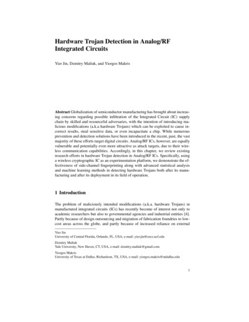
Integrated Circuits (ICs) 9Integrated Circuits versus Discrete ComponentsThe tracks linking components inside an integrated circuit have widthsmeasured in fractions of a millionth of a meter and lengths measured in millimeters. By comparison, the tracks linking components on a circuit board areorders of magnitude wider and have lengths measured in tens of centimeters.Thus, the transistors used to drive tracks inside an integrated circuit can bemuch smaller than those used to drive their circuit board equivalents, andsmaller transistors use less power. Additionally, signals take a finite time topropagate down a track, so the shorter the track, the faster the signal.A single integrated circuit can contain tens (sometimes hundreds) ofmillions of transistors. A similar design based on discrete components would betremendously more expensive in terms of price, size, operating speed, powerrequirements, and the time and effort required to design and manufacture th,system. Additionally, every solder joint on a circuit board is a potential sourceof failure, which affects the reliability of the design. Integrated circuits reducethe number of solder joints and hence improve the reliability of the system.In the past, an electronic system was typically composed of a number ofintegrated circuits, each with its own particular function (say a microprocessor,a communications function, some memory devices, etc.). For many of today'shigh-end applications, however, electronics engineers are combining all of thesefunctions on a single device, which may be referred to as a system-on-chip(SoC).Different Types of ICsThe first integrated circuit a simple phase shift oscillator was constructedin 1958.11 Since that time, a plethora of different device types have appearedon the scene. There are far too many different integrated circuit types for us tocover in this book, but some of the main categories along with their approximate dates of introduction are shown in Figure 14-18. lz11 The first integrated circuits typically contained around six transistors. By the latter half of the1960s, devices containing around 100 transistors were reasonably typical.12 The white portions of the timeline bars in this figure indicate that although early incarnationsof these technologies may have been available, they perhaps hadn't been enthusiasticallyreceived during this period. For example, Xilinx introduced the world's first FPGA as earlyas 1984, but many design engineers didn't really become interested in these little rapscallionsuntil the late 1980s.155
156 9 C h a p t e r Fourteen1945 1950 1955 1960 1965 1970 1975 1980 1985 1990 1995 2000FPGAsPLDsASICsMicroprocessorsSRAMs & DRAMsICs (General)TransistorsFigure 14-18. Timeline of device introductions (dates are approximate)Memory devices (in particular SRAMs and DRAMs) are introduced inChapter 15; programmable integrated circuits (PLDs and FPGAs) arepresented in Chapter 16; and application-specific integrated circuits (ASICs)are discussed in Chapter 17.Technology ConsiderationsTransistors are available in a variety of flavors called families or technologies.One of the first to be invented was the bipolarjunction transistor (BJT), whichwas the mainstay of the industry for many years. If bipolar transistors areconnected together in a certain way, the resulting logic gates are classed astransistor-transistor logtc (TTL). An alternative method of connecting the sametransistors results in logic gates classed as emitter-coupled logic (ECL). Anotherfamily called metal-oxide semiconductor field-effect transistors (MOSFETs) wereinvented some time after bipolar junction transistors. Complementary metaloxide semiconductor (CMOS) logic gates are based on NMOS and PMOSMOFSETs connected together in a complementary manner.Logic gates constructed in TTL are fast and have strong drive capability,but consume a relatively large amount of power. Logic gates implemented inCMOS are a little slower than their TTL equivalents and have weaker drivecapability, but their static (non-switching) power consumption is extremelylow. Technology improvements continue to yield lower-power TTL devicesand higher-speed CMOS devices. Logic gates built in ECL are substantiallyfaster than their TTL counterparts, but consume correspondingly more power.
I n t e g r a t e d Circuits (ICs) 9Finally, gates fabricated using the gallium arsenide (GaAs) semiconductor as asubstrate are approximately eight times faster than their silicon equivalents, butthey are expensive to produce, and so are used for specialist applications only.If an integrated circuit containing millions of transistors were constructedentirely from high-power transistors, it could literally consume enough powerto incinerate itself (or at least melt itself down into an undistinguished puddleof gunk). As a compromise, some integrated circuits use a combination oftechnologies. For example, the bulk of the logic gates in a device may beimplemented in low-power CMOS, but the gates driving the output pins maybe constructed from high-drive TTL. A more extreme example is that ofBiCMOS (BipolarCMOS), in which the function of every primitive logic gateis implemented in low-power CMOS, but the output stage of each gate useshigh-drive bipolar transistors.Supply VoltagesTowards the end of the 1980s and the beginning of the 1990s, the majorityof circuits using TTL, CMOS, and BiCMOS devices were based on a 5.0-voltsupply. However, increasing usage of portable personal electronics such asnotebook computers and cellular telephones began to drive the requirementfor devices that consume and dissipate less power. One way to reduce powerconsumption is to lower the supply voltage, so by the mid-to-late 1990s, themost common supplies were 3.3 volts for portable computers and 3.0 volts forcommunication systems. By 2002, some specialist applications had plunged to1.8 volts, with even lower supplies on the horizon. Unfortunately, lowering thesupply voltage can drastically affect the speed of traditional technologies andgreatly lessens any speed advantages of BiCMOS over CMOS. A relativelynew low-voltage contender that appeared in the latter half of the 1990s wasBiNMOS, in which complex combinations of bipolar and NMOS transistorsare used to form sophisticated output stages providing both high speed and lowstatic power dissipation.Equivalent GatesOne common metric used to categorize an integrated circuit is the numberof logic gates it contains. However, difficulties may arise when comparingdevices, as each type of logic function requires a different number of transistors.157
158 9 C h a p t e r FourteenThis leads to the concept of an equivalent gate, whereby each type of logicfunction is assigned an equivalent gate value, and the relative complexity of anintegrated circuit is judged by summing its equivalent gates. Unfortunately, thedefinition of an equivalent gate can vary, depending on whom one is talking to.A reasonably common convention is for a 2-input NAND to represent oneequivalent gate. A more esoteric convention defines an ECL equivalent gate asbeing "one-eleventh the minimum logic required to implement a single-bit full-adder,"while some vendors define an equivalent gate as being equal to an arbitrarynumber of transistors based on their own particular technology. The best policyis to establish a common frame of reference before releasing a firm grip on yourhard-earned lucre.The acronyms SSI, MSI, LSI, VLSI, and ULSI represent Small-, Medium-,Large-, Very-Large-, and Ultra-Large-Scale Integration, respectively. By oneconvention, the number of gates represented by these terms are: SSI (1-12),MSI (13-99), LSI (100-999), VLSI ( 1,000-999,999), and ULSI ( 1,000,000or more).Device GeometriesIntegrated circuits are also categorized by their geometries, meaning the sizeof the structures created on the substrate. For example, a 1 m 13 CMOS devicehas structures that measure one-millionth of a meter. The structures typicallyembraced by this description are the width of the tracks and the length of thechannel between the source and drain diffusion regions; the dimensions ofother features are derived as ratios of these structures.Geometries are continuously shrinking as fabrication processes improve.In 1990, devices with 1 m geometries were considered to be state of the art,and many observers feared that the industry was approaching the limits ofma
Integrated Circuits (ICs) In the 1950s, transistors and other electronic components were available only in individual packages. These discrete components were laid out on a circuit board and hand connected using separate wires. At that time, an electronic gate capable of s