Transcription
PCAN-USBUser ManualUser Manual 3.0.1 2022 PEAK-System Technik GmbH
Relevant ProductsModelProduct namePCAN-USBPart numberIPEH-002021PCAN-USB opto-decoupledGalvanic isolation for CAN interfaceIPEH-002022The cover picture shows both products, the PCAN-USB with the red and the PCAN-USBopto-decoupled with the grey cable strain relief.ImprintPCAN is a registered trademark of PEAK-System Technik GmbH. CiA is a registered community trade markof CAN in Automation e.V.All other product names in this document may be the trademarks or registered trademarks of theirrespective companies. They are not explicitly marked by or . 2022 PEAK-System Technik GmbHDuplication (copying, printing, or other forms) and the electronic distribution of this document is onlyallowed with explicit permission of PEAK-System Technik GmbH. PEAK-System Technik GmbH reserves theright to change technical data without prior announcement. The general business conditions and theregulations of the license agreement apply. All rights are reserved.PEAK-System Technik GmbHOtto-Röhm-Straße 6964293 DarmstadtGermanyPhone: 49 6151 8173-20Fax: 49 6151 ment version 3.0.1 (2022-04-21)Relevant ProductsUser Manual 3.0.1PCAN-USB 2022 PEAK-System Technik GmbH2
ContentsImprintRelevant ProductsContents1 Introduction1.1 Properties at a Glance1.2 System Requirements1.3 Scope of Supply2 Settings2.1 Voltage Supply of External Devices2.2 Internal Termination3 Installation3.1 Install Device Driver Setup3.2 Connecting the CAN Interface3.3 Check Operational Readiness4 Connecting the CAN Bus4.1 Connection over D-Sub Connector4.2 Cabling4.3 Example Application under Windows5 Operation5.1 Status LED5.2 Unplugging the USB Connection5.3 Distinguishing several PCAN-USB Interfaces6 CAN Monitor PCAN-View6.1 CAN interface initialize6.2 Transmit CAN message6.3 Additional Tabs7 API PCAN-Basic7.1 Features of PCAN-Basic7.2 Principle Description of the API8 Technical SpecificationsAppendix A CE CertificateAppendix B Dimension DrawingsContents PCAN-USBUser Manual 3.0.1 2022 PEAK-System Technik 0313234353
Appendix C Quick ReferenceAppendix D LinuxContents PCAN-USBUser Manual 3.0.1 2022 PEAK-System Technik GmbH36374
1IntroductionThe PCAN-USB interface enables simple connection to CAN networks. Its compactplastic casing makes it suitable for mobile applications. The opto-decoupled versionguarantees galvanic isolation of up to 500 Volts between the PC and the CAN side.The monitor software PCAN-View and the programming interface PCAN-Basic for thedevelopment of applications with CAN connection are included in the scope ofsupply and support CAN FD.Device drivers exist for different operating systems, so programs can easily access aconnected CAN bus.This manual describes the use of the CAN interface with Windows.Device drivers and application information for Linux:www.peak-system.com/quick/DL-Driver-EAt the end of this manual you can find a Quick Reference with briefinformation about the installation and operation of the PCAN-USBinterface.1 Introduction PCAN-USBUser Manual 3.0.1 2022 PEAK-System Technik GmbH5
1.1Properties at a Glance CAN interface for the USB connection(Full-Speed mode, compatible with USB 1.1, USB 2.0, and USB 3.0) High-speed CAN connection (ISO 11898-2) Compliant with CAN specifications ISO 11898-1 for CAN Bit rates from 5 kbit/s up to 1 Mbit/s CAN bus connection via D-Sub, 9-pin (in accordance with CiA 303-1) Time stamp resolution 42 µs NXP CAN controller SJA1000, 16 MHz clock frequency NXP CAN transceiver PCA82C251 Galvanic isolation on the CAN connection up to 500 V(only PCAN-USB opto-decoupled) CAN termination can be activated through a solder jumper 5-Volt supply to the CAN connection can be connected through asolder jumper, e.g. for external bus converter Voltage supply via USB Extended operating temperature range from -40 to 85 C (-40 to 185 F)1 Introduction PCAN-USBUser Manual 3.0.1 2022 PEAK-System Technik GmbH6
1.2 System RequirementsComputer with operating system Windows 11 (64 bit), 10 (32/64 bit) or Linux (32/64-bit) a vacant USB port (USB 1.1, USB 2.0, or USB 3.0) or a vacant USB port at a self-powered USB hub1.3 Scope of Supply PCAN-USBDownloads Device drivers for Windows 11 (64 bit), 10 (32/64 bit) and Linux (32/64-bit) CAN monitor PCAN-View for Windows Programming interface PCAN-Basic for developing applications with CANconnection Programming interfaces for standardized protocols from the automotive sector1 Introduction PCAN-USBUser Manual 3.0.1 2022 PEAK-System Technik GmbH7
2SettingsThe following describes the settings for the power supply of external devices and theinternal termination. If you do not need any of these settings, skip this chapter.2.1 Voltage Supply of External DevicesOptionally, an external power supply can be connected via the D-Sub connectorusing solder bridges at pin 1 and/or pin 9 on the D-Sub connector. This allowsexternal devices to be supplied with a voltage of 5 V DC, such as the PCAN-TJA1054bus converter for Low-speed CAN. Pin 1 and pin 9 are not assigned at delivery andwith the PCAN-USB opto-decoupled only pin 1 is available up to S/N 199999.The opto-decoupled model of the CAN interface contains an interconnectedDC/DC converter. Therefore, the current output is limited to 50 mA.2.1.1 Activate Power SupplyRisk of short circuit! Soldering on the CAN interface may only beperformed by qualified electrical engineering personnel.Attention! Electrostatic discharge (ESD) can damage or destroycomponents on the card. Take precautions to avoid ESD.2 Settings PCAN-USBUser Manual 3.0.1 2022 PEAK-System Technik GmbH8
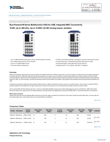
1. Open the CAN interface casing. Push the latches on both sides cautiously with aslotted screwdriver.2. Remove the circuit board.3. Set the solder bridges according to the model of the PCAN-USB on the intendedposition on the circuit board (see below).4. For assembly, place the circuit board on the upper half of the housing. The strainrelief and the LED must be in the corresponding recesses.5. Press the lower half of the housing onto the upper half of the housing until thelatches engage.PCAN-USB (IPEH-002021) to S/N 199999,solder field JP3PCAN-USB (IPEH-002021) from S/N 200000,solder field JP32 Settings PCAN-USBUser Manual 3.0.1 2022 PEAK-System Technik GmbH9
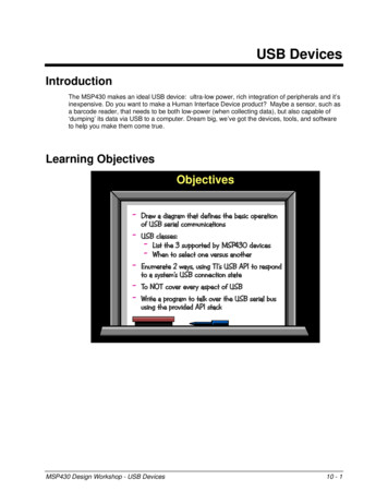
PCAN-USB opto-decoupled (IPEH-002022) to S/N 199999,solder field R11PCAN-USB opto-decoupled (IPEH-002022) from S/N 200000,solder field JP3PCAN-USB modelSolder field5 V supply on the D-Sub connectorWithout(default)IPEH-002021to S/N 199999JP3IPEH-002021from S/N 200000JP3IPEH-002022 (opto-dec.)to S/N 199999R11IPEH-002022 (opto-dec.)from S/N 200000JP32 Settings PCAN-USBUser Manual 3.0.1 2022 PEAK-System Technik GmbHPin 1Pin 9notapplicablePin 1 andPin 9notapplicable10
Attention! The voltage supply for external devices is not protectedseparately. Therefore, turn off the computer before you connect anddisconnect CAN cables or peripheral systems. Consider that somecomputers still supply the USB ports with power even when they areturned off (standby operation).2 Settings PCAN-USBUser Manual 3.0.1 2022 PEAK-System Technik GmbH11
2.2 Internal TerminationOnly applicable from S/N 200000The internal termination can be activated by solder jumpers on the circuit board toterminate one end of the CAN bus. At delivery the termination is not activated.Tipp: We recommend to do termination at the CAN cabling, for examplewith the terminating resistors PCAN-Term (IPEK-003002) orPCAN-MiniTerm (IPEK-003002-Mini). Thus, CAN nodes can be flexiblyconnected to the bus.2.2.1 Activate Internal TerminationRisk of short circuit! Soldering on the CAN interface may only beperformed by qualified electrical engineering personnel.Attention! Electrostatic discharge (ESD) can damage or destroycomponents on the card. Take precautions to avoid ESD.1. Open the CAN interface casing. Push the latches on both sides cautiously with aslotted screwdriver.2. Remove the circuit board.3. Set the solder bridges according to the model of the PCAN-USB on the intendedposition on the circuit board (see below).4. For assembly, place the circuit board on the upper half of the housing. The strainrelief and the LED must be in the corresponding recesses.5. Press the lower half of the housing onto the upper half of the housing until thelatches engage.2 Settings PCAN-USBUser Manual 3.0.1 2022 PEAK-System Technik GmbH12
PCAN-USB (IPEH-002021) to S/N 199999,solder fields for the CAN bus terminationPCAN-USB opto-decoupled (IPEH-002022) from S/N 200000,solder fields for the CAN bus terminationPCAN-USB modelTermination High-speed CAN bus 120 ΩWithout (default)ActivatedIPEH-002021from S/N 200000IPEH-002022 (opto-dec.)from S/N 2000002 Settings PCAN-USBUser Manual 3.0.1 2022 PEAK-System Technik GmbH13
3InstallationThis chapter covers the software setup for the PCAN-USB interface under Windowsand the connection of the CAN interface to the computer.Note: For installation on Linux, see Appendix D Linux.Install the driver before you connect the CAN interface.3.1 Install Device Driver Setup1. Download the device driver setup from our website:www.peak-system.com/quick/DL-Driver-E2. Unpack the file PEAK-System Driver-Setup.zip3. Double-click the file PeakOemDrv.exeThe driver setup starts.4. Follow the program instructions.3 Installation PCAN-USBUser Manual 3.0.1 2022 PEAK-System Technik GmbH14
3.2 Connecting the CAN InterfaceMalfunction! Do not use a USB extension cable to connect theCAN interface to the computer. Extension cables does not comply withthe USB specification.1. Connect the CAN interface to a USB port of the computer or of a connected USBhub. The computer can remain powered on.Windows detects the new hardware and completes the driver installation.2. Check the LED on the CAN interface. If the LED is on, then the driver wasinitialized successfully.3.3 Check Operational Readiness1. Open the Windows Start menu.2. Type Peak Settings and press Enter .The window PEAK Settings appears.3. Select CAN Hardware.The connected CAN interface is displayed.3 Installation PCAN-USBUser Manual 3.0.1 2022 PEAK-System Technik GmbH15
4Connecting the CAN Bus4.1 Connection over D-Sub ConnectorAfter the CAN interface is connected, a CAN bus can be connected to theD-Sub connector. The pin assignment for CAN corresponds to the specificationCiA 303-1:AssignmentPinCAN V (optional)1, 9CAN Low2CAN High7CAN GND3, 6Not connected4, 5, 8D-Sub plugLow power devices can be supplied directly with 5 Volts over pin 1 and pin 9 of theCAN connector, for example bus converters. Pin 1 and/or pin 9 are not in use at thedelivery state. For more information see section 2.1 Voltage Supply of ExternalDevices.Tip: Connect a CAN bus with a different transmission standard via a busconverter. PEAK-System offers different bus converter modules like thePCAN-TJA1054 for a Low-speed CAN bus according to ISO 11898-3.4 Connecting the CAN Bus PCAN-USBUser Manual 3.0.1 2022 PEAK-System Technik GmbH16
4.2 Cabling4.2.1 TerminationThe High-speed CAN bus (ISO 11898-2) must be terminated with 120 Ω on both ends.The termination prevents interfering signal reflections and ensures the properoperation of the transceivers of the connected CAN nodes (CAN interfaces,control devices).The PCAN-USB interface to S/N 199999 does not have an internal termination. FromS/N 200000 it has an optional internal termination with 120 Ω. See the previoussection 2.2 Internal Termination for information about activation.4.2.2 Example of a ConnectionThis example shows a connection between the PCAN Interface and a control unit(ECU). The upper example shows a connection with a cable which is terminated with120 Ω at both ends. At the lower example the connection is made with terminationadapters.4 Connecting the CAN Bus PCAN-USBUser Manual 3.0.1 2022 PEAK-System Technik GmbH17
4.2.3 Maximum Bus LengthThe maximum bus length depends primarily on the bit rate:Nominal bit rate Buslength1 Mbit/s40 m500 kbit/s110 m250 kbit/s240 m125 kbit/s500 m50 kbit/s1.3 km20 kbit/s3.3 km10 kbit/s6.6 km5 kbit/s13 kmThe listed values have been calculated on the basis of an idealized system and candiffer from reality.4.3 Example Application under WindowsAs an example application for accessing the CAN interface, run the CAN monitorPCAN-View from the Windows Start menu.4 Connecting the CAN Bus PCAN-USBUser Manual 3.0.1 2022 PEAK-System Technik GmbH18
5Operation5.1 Status LEDThe LED can be in the following states:StatusMeaningOnThere is a connection to the driver of the operating system.Slow blinkingA software application is connected to the CAN interface.Quick blinkingData is transmitted via the connected CAN bus.5.2 Unplugging the USB ConnectionThe PCAN-USB interface can be disconnected from the computer without furtheractions. In Windows, the interface is not listed under "Safely Remove Hardware".5.3 Distinguishing several PCAN-USB InterfacesYou can operate several PCAN-USB interfaces on a single computer at the same time.The supplied program PCAN-View allows the assignment of device IDs in order todistinguish the CAN interfaces in a software environment.5 Operation PCAN-USBUser Manual 3.0.1 2022 PEAK-System Technik GmbH19
6CAN Monitor PCAN-ViewThe CAN monitor PCAN-View is a Windows software for viewing, sending, andrecording CAN and CAN FD messages. The software is installed with the installationof the device driver package under Windows.In the following the initialization of a CAN interface is described as an example.Detailed information about using PCAN-View can be found in the program windowunder the menu item Help.6 CAN Monitor PCAN-View PCAN-USBUser Manual 3.0.1 2022 PEAK-System Technik GmbH20
6.1 CAN interface initialize1. Open the program PCAN-View via the Windows Start menu.Depending on the CAN interface the Connect dialog is displayed with or withoutsettings for CAN FD.CANCAN FDCAN-InterfaceList entry in Available HardwareUSB Interface, 1-channelsee example aboveUSB Interface, 2-channelPCIe Interface, 2-channel2. If there are several CAN interfaces, select the desired interface. For multiplechannels, select the desired channel from the list.3. Enter the bit rate(s) and other settings according to the connected CAN bus.6 CAN Monitor PCAN-View PCAN-USBUser Manual 3.0.1 2022 PEAK-System Technik GmbH21
4. Confirm the entries with OK. The main window appears and displays the Receive /Transmit tab.5. For initializing another channel or CAN interface, open another instance of PCANView.6 CAN Monitor PCAN-View PCAN-USBUser Manual 3.0.1 2022 PEAK-System Technik GmbH22
6.2 Transmit CAN message1. Select the menu command Transmit / New Message.Depending on the CAN interface, the dialog box New Transmit Message isdisplayed with or without settings for CAN FD.CANCAN FD1. Enter the ID, Length and Data of the message. Other settings can be madeaccording to the connected CAN bus.2. Enter a value into the Cycle Time field to choose manually or periodically messagetransmission.Enter a value greater than 0 to transmit periodically.Enter the value 0 to transmit only manually.3. Confirm the entries with OK.The created transmit message appears on the Receive / Transmit tab.4. To send the message manually, select the menu command Transmit Send orpress the space bar.The manual transmission process is performed additionally for periodicallytransmitted CAN messages.6 CAN Monitor PCAN-View PCAN-USBUser Manual 3.0.1 2022 PEAK-System Technik GmbH23
6.3 Additional TabsDepending on the CAN-Interface, additional tabs are available.6.3.1 Trace TabThe tracer (data logger) records the communication of the CAN bus in linear orring buffer mode. The trace data can be saved to a file.6 CAN Monitor PCAN-View PCAN-USBUser Manual 3.0.1 2022 PEAK-System Technik GmbH24
6.3.2 CAN-Interface TabThe CAN-Interface tab shows information about the hardware and the used Windowsdevice driver. In this case exemplary for the PCAN-miniPCIe FD. Depending on theCAN-Interface, a hardware ID can be determined to distinguish several interfaces ofthe same type. For interfaces with CAN FD a transmission according to "ISO" or"Non-ISO" can be set as default of the hardware.6 CAN Monitor PCAN-View PCAN-USBUser Manual 3.0.1 2022 PEAK-System Technik GmbH25
6.3.3 Bus Load TabThe Bus Load tab displays the current bus load, its time history and statisticalinformation of the connected CAN channel.6.3.4 Error Generator Tab6 CAN Monitor PCAN-View PCAN-USBUser Manual 3.0.1 2022 PEAK-System Technik GmbH26
Via the Error Generator tab the communication on the CAN bus in test environmentsor during the development of CAN buses can be disturbed in a controlled way by 6consecutive dominant bits. This is a violation of the CAN protocol on the CAN buswhich must be recognized as an error by the connected CAN nodes.Note: The Error Generator should only be used by experienced usersand in the development environment. For further information, pleasecontact our customer support: support@peak-system.comYou can destroy CAN frames with the error generator by one of two methods: once after activation repeatedly at specific intervals related to a CAN ID6 CAN Monitor PCAN-View PCAN-USBUser Manual 3.0.1 2022 PEAK-System Technik GmbH27
Destroy Single CAN FrameThe Destroy Single Frame area refers to the next CAN frame that is recognizedby the plug-in card after activation.1. Enter the Bit Position where in the CAN frame the error is to be generated. The bitposition must start after the identifier. The count includes the stuff bits.2. Execute the destroy action with Do it.The next received or transmitted CAN frame will be destroyedat the selected bit position.Destroy Multiple CAN Frames1. Enter the CAN ID of the CAN frame that is intended to be destroyed multipletimes. The following specifications refer to this ID.2. Enter the Bit Position where in the CAN frame the error is to be generated. The bitposition must start after the identifier. The count includes the stuff bits.3. If CAN messages are to be sent unharmed before being destroyed, specify theNumber of Frames to ignore.4. Determine the Number of Frames to destroy.5. Confirm the entries with Apply to activate the error generator.6. Stop destroying further CAN frames with Disable.6 CAN Monitor PCAN-View PCAN-USBUser Manual 3.0.1 2022 PEAK-System Technik GmbH28
7API PCAN-BasicThe intended use of PCAN-Basic requires compliance with the licenserights. Read the license agreement for end users at:https://www.peak-system.com/quick/eulaThe programming interface (API) PCAN-Basic provides basic functions for theconnection of own programs to the CAN-Interface of PEAK-System. PCAN-Basic is theinterface between the program and the device driver. In Windows operating systemsthis is a DLL (Dynamic Link Library) and in Linux operating systems an SO (DynamicShared Object). PCAN-Basic is designed to be cross-operating system compatible.Software projects can be ported between supported systems with little effort.With the installation of the device driver package under Windows the DLL files of theAPI PCAN-Basic are placed in the system folder. Examples for all commonprogramming languages as well as libraries and help files are available as downloadpackage at: www.peak-system.com/quick/DL-Develop-E7 API PCAN-Basic PCAN-USBUser Manual 3.0.1 2022 PEAK-System Technik GmbH29
For Linux a download of the API is available under this link. For a use of PCAN-Basicanother driver package with chardev driver is needed, because an access underSocketCAN is not possible. The "Driver Package for Proprietary Purposes", the usermanual, and further information about the implementation can be found atwww.peak-system.com/linux7.1 Features of PCAN-Basic Thread-safe API for developing applications with CAN and CAN FD connections Supports CAN specifications ISO 11898-1 for CAN and CAN FD Supports the operating systems: Windows 11 (64 bit), 10 (32/64 bit) Linux (32/64-bit) Multiple PEAK-System applications and your own can be operated on a physicalchannel at the same time Single DLL (Win) / SO (Linux) for all supported hardware types Use of up to 16 channels for each hardware type Simple switching between channels Access to the CAN channels of a PCAN-Gateway via the PCAN-LAN device type Driver-internal buffering under Windows of up to 32,768 CAN messages perCAN channel Precision of time stamps on received messages up to 1 μs(depending on the PEAK CAN interface used) Supports PEAK-System‘s trace formats v1.1 for CAN andv2.0 for CAN FD applications Access to specific hardware parameters, such as Listen-only mode Notification of the application through Windows events when a message isreceived Support of CAN error frames Confirmation of physical transmission by CAN echo frames Extended system for debugging operations7 API PCAN-Basic PCAN-USBUser Manual 3.0.1 2022 PEAK-System Technik GmbH30
Multilingual debugging output Output language depends on operating systems Debugging information can be defined individually7.2 Principle Description of the APIThe sequence of accessing the CAN interface is divided into three phases:InitializationA CAN channel must be initialized before using it. This is done by the simple call ofthe function CAN Initialize for CAN and CAN InitializeFD for CAN FD. PerCAN interface type the API allows the simultaneous use of up to 16 CAN channels.After a successful initialization the CAN channel is ready. No further configurationsteps are required.InteractionFor receiving and transmitting messages the functions CAN Read and CAN Writeas well as CAN ReadFD and CAN WriteFD are available depending on theinitialization mode. Additional settings can be made, such as setting up messagefilters to confine to specific CAN IDs or setting the CAN controller to Listen-onlymode.For the receiving CAN messages, events can be configured for automatic notificationof an application (client). This offers the following advantages: The application no longer needs to check for received messages periodically(no polling). The response time at reception is reduced.CompletionTo end the communication the function CAN Uninitialize is called in order torelease the reserved resources for the CAN channel, among others. In addition theCAN channel is marked as "Free" and is available to other applications.7 API PCAN-Basic PCAN-USBUser Manual 3.0.1 2022 PEAK-System Technik GmbH31
8Technical SpecificationsConnectorsComputerUSB plug type ACAND-Sub (m), 9 pins,Pin assignment according to specification CiA 303-1USBto S/N 199999 USB 1.1, from S/N 200000 USB 2.0,Full-Speed mode (compatible withUSB 1.1, USB 2.0, and USB 3.0)CANProtocols on OSI layer 2CAN ISO 11898-1:2015, 2.0Physical transmission, OSI layer 1ISO 11898-2 (High-speed CAN)CAN Bit ratesNominal:ControllerNXP SJA1000TransceiverNXP PCA82C251Galvanic isolationPCAN-USB:PCAN-USB opto:noneup to 500 VSupply for external devicesvia D-Sub pin 1 / pin 9PCAN-USB:PCAN-USB opto1:5 V, max. 100 mA5 kbit/s to 1 Mbit/s5 V, max. 50 mAnot activated at deliveryInternal terminationto S/N 199999 not available,from S/N 200000 via solder bridges,not activated at deliveryTime stamp resolution42 µs1Pin 9 only from S/N 200000Power supplySupply voltage 5 V DC (via USB port)Power consumptionmax. 200 mA8 Technical Specifications PCAN-USBUser Manual 3.0.1 2022 PEAK-System Technik GmbH32
MeasuresSize (w/o cable)PCAN-USB:PCAN-USB opto:Length (connection cable)approx. 0.75 mWeight (with cable)PCAN-USB:PCAN-USB opto:75 x 43 x 22 mm87 x 43 x 22 mm78 g83 gEnvironmentOperating temperature-40 to 85 C / -40 to 185 FTemperature for storage andtransport-40 to 100 C / -40 to 212 FRelative humidity15 to 90 %, not condensingIngress protection (IEC 60529)IP20ConformityRoHSEU Directive 2011/65/EU (RoHS 2) 2015/863/EUDIN EN IEC 63000:2019-05; VDE 0042-12:2019-05EMCEU Directive 2014/30/EUDIN EN 55024:2016-05; VDE 0878-24:2016-05DIN EN 55032:2016-02; VDE 0878-32:2016-028 Technical Specifications PCAN-USBUser Manual 3.0.1 2022 PEAK-System Technik GmbH33
Appendix A CE CertificateAppendix A CE Certificate PCAN-USBUser Manual 3.0.1 2022 PEAK-System Technik GmbH34
Appendix B Dimension DrawingsPCAN-USBPCAN-USB opto-decoupledAppendix B Dimension Drawings PCAN-USBUser Manual 3.0.1 2022 PEAK-System Technik GmbH35
Appendix C Quick ReferenceSoftware/Hardware Installation under WindowsDownload the device drivers installation package from our websitewww.peak-system.com/quick/DL-Driver-E. Install the driver before you install theCAN interface.After driver installation connect the CAN interface to a USB port of the computer orof a connected USB hub. The new hardware is recognized by Windows and the driveris initialized. The LED on the interface then is lit.Check the operational readiness. Open the Windows Start menu. Type PeakSettings and press Enter . The window PEAK Settings appears. The connected USBinterface is displayed under CAN Hardware.Getting Started under WindowsRun the CAN monitor PCAN-View from the Windows Start menu as a sampleapplication for accessing the CAN interface. For initialization of the CAN interfaceselect the desired CAN channel and CAN bit rate.Status LEDStatusMeaningOnThere's a connection to a driver of the operating system.Slow blinkingA software application is connected to the CAN interface.Quick blinkingData is transmitted via the connected CAN bus.High-speed CAN connector (D-Sub, 9 pins)AssignmentPinCAN V (optional)1, 9CAN Low2CAN High7CAN GND3, 6Not connected4, 5, 8D-Sub plugAppendix C Quick Reference PCAN-USBUser Manual 3.0.1 2022 PEAK-System Technik GmbH36
Appendix D LinuxDepending on the Kernel version, device drivers for the CAN interfaces from PEAKSystem are already included in the operating system. The CAN interfaces are treatedas network devices (SocketCAN, netdev). You can find the documentation forSocketCAN under: g/can.txtThe command grep PEAK /boot/config- uname -r lists the availabledrivers. The following table shows the PCAN-Interfaces and from which kernel versionthey are supported.PCAN-InterfaceKernel versionPCAN-PCIPCAN-PCI BPCAN-USB ProPCAN-PCI AN-PCI/104-ExpressPCAN-USB FD 3.2 3.4 3.7PCAN-USB Pro FD 4.0PCAN-Chip USB 4.11PCAN-PCI Express FDPCAN-PCI/104-Express FD 4.12PCAN-miniPCIe FDPCAN-M.2PCAN-Chip PCIe FD 4.12PCAN-Chip PCIe 4.3PCAN-USB X6 4.9Whether the required driver for the PCAN-Interface is present and loaded can bechecked with the following command: lsmod grep peak check. If theinitialization was successful, the response line starts with peak usb or peak pci.If the required drivers are not listed, install the "Driver Package for ProprietaryPurposes". The download, the user manual for the driver, and the corresponding"Implementation Details" can be found under: www.peak-system.com/linuxThis driver package is also needed to use the APIs based on the chardev driver, forexample PCAN-Basic, libpcan, or libpcanfd.Appendix D LinuxUser Manual 3.0.1PCAN-USB 2022 PEAK-System Technik GmbH37
PCAN-USBopto-decoupled(IPEH-002022)toS/N199999, solderfieldR11 PCAN-USBopto-decoupled(IPEH-002022)fromS/N200000, solderfieldJP3 PCAN-USBmodel Solderfield 5VsupplyontheD-Subconnector