Transcription
PCAN-PC/104CAN Interface for PC/104User ManualDocument version 2.6.0 (2019-03-06)
PCAN-PC/104 – User ManualRelevant productsProduct nameModelPart numberPCAN-PC/104 Single ChannelOne CAN channelIPEH-002054PCAN-PC/104 Dual ChannelTwo CAN channelsIPEH-002055PCAN-PC/104 Single Channelopto-decoupledOne CAN channel, galvanicisolation for CAN connectionIPEH-002056PCAN-PC/104 Dual Channelopto-decoupledTwo CAN channels, galvanicisolation for CAN connectionsIPEH-002057The cover picture shows the product PCAN-PC/104 Dual Channel opto-decoupled.Other product models have an identical form factor but vary in equipment.PCAN is a registered trademark of PEAK-System Technik GmbH. CANopen andCiA are registered community trade marks of CAN in Automation e.V.All other product names mentioned in this document may be the trademarks orregistered trademarks of their respective companies. They are not explicitly markedby “ ” and “ ”.Copyright 2019 PEAK-System Technik GmbHDuplication (copying, printing, or other forms) and the electronic distribution of thisdocument is only allowed with explicit permission of PEAK-System Technik GmbH.PEAK-System Technik GmbH reserves the right to change technical data withoutprior announcement. The general business conditions and the regulations of thelicense agreement apply. All rights are reserved.PEAK-System Technik GmbHOtto-Roehm-Strasse 6964293 DarmstadtGermanyPhone: 49 (0)6151 8173-20Fax: 49 (0)6151 ment version 2.6.0 (2019-03-06)2
PCAN-PC/104 – User ManualContents11.11.21.32Introduction5Properties at a GlanceSystem RequirementsScope of SupplyConfiguration and Installation56782.1 Configuring the Card2.1.1Interrupt2.1.2I/O Address Range2.2 Installing the Software2.3 Installing the Hardware2.4 Modifying the Computer's BIOS Settings2.4.1Indicating Used Interrupts2.4.2Deactivating the APIC Mode89101213151516317Connecting the CAN Bus3.1 Connection over D-Sub Connector3.1.1Slot Bracket with D-Sub Connectors3.2 Voltage Supply of External Devices3.3 Cabling3.3.1Termination3.3.2Example of a Connection3.3.3Maximum Bus Length17192022222223424Software and API4.1 Monitor Software PCAN-View4.1.1Receive/Transmit Tab4.1.2Trace Tab4.1.3PCAN-PC/104 Tab4.1.4Status Bar32427293030
PCAN-PC/104 – User Manual4.2 Linking Own Programs with PCAN-Basic4.2.1Features of PCAN-Basic4.2.2Principle Description of the API4.2.3Notes about the License31323334535Technical SpecificationsAppendix ACE Certificate37Appendix BDimension Drawing38Appendix CQuick Reference394
PCAN-PC/104 – User Manual1IntroductionThe PCAN-PC/104 card enables the connection of one or two CANnetworks to a PC/104 system. Multiple PCAN-PC/104 cards caneasily be operated using interrupt sharing.The card is available as a single or dual-channel version. The optodecoupled versions also guarantee galvanic isolation of up to 500Volts between the PC and the CAN sides.The monitor software PCAN-View and the programming interfacePCAN-Basic for the development of applications with CANconnection are included in the scope of supply.Device drivers exist for different operating systems, so programscan easily access a connected CAN bus.Tip: At the end of this manual (Appendix C) you can find aQuick Reference with brief information about the installationand operation of the PCAN-PC/104 card.1.1Properties at a GlanceForm factor PC/104Multiple PC/104 cards can be operated in parallel(interrupt sharing)14 port and 8 interrupt addresses are available for configurationusing jumpers1 or 2 High-speed CAN channels (ISO 11898-2)Bit rates from 5 kbit/s up to 1 Mbit/s5
PCAN-PC/104 – User ManualCompliant with CAN specifications 2.0A (11-bit ID)and 2.0B (29-bit ID)Connection to CAN bus through D-Sub slot bracket,9-pin (in accordance with CiA 303-1)NXP SJA1000 CAN controller, 16 MHz clock frequencyNXP PCA82C251 CAN transceiver5-Volt supply to the CAN connection can be connected through asolder jumper, e.g. for external bus converterGalvanic isolation on the CAN connection up to 500 V (onlyopto-decoupled models), separate for each CAN channelExtended operating temperature range of -40 to 85 C(-40 to 185 F)Note: This manual describes the use of the PCAN-PC/104 cardwith Windows. You can find device drivers for Linux and thecorresponding application information on the provided DVD inthe directory branch Develop and on our website underwww.peak-system.com/linux.1.2System RequirementsPC/104 stack with ISA bus (according to the PC/104 specification)Operating system Windows 10, 8.1, 7 (32-bit),or Windows CE 6.x (x86 and ARMv4 processor support),or Linux (32/64-bit)6
PCAN-PC/104 – User Manual1.3Scope of SupplyPCAN-PC/104 cardSlot bracket with D-Sub connectors for the CAN busDevice drivers for Windows 10, 8.1, 7 (32-bit)and Linux (32/64-bit)Device driver for Windows CE 6.x(x86 and ARMv4 processor support)CAN monitor PCAN-View for WindowsCAN monitor PCAN-View for DOSProgramming interface PCAN-Basic for developing applicationswith CAN connectionProgramming interfaces for standardized protocols from theautomotive sectorManual in PDF format7
PCAN-PC/104 – User Manual2Configuration andInstallationThis chapter covers the configuration, the software setup for thePCAN-PC/104 card under Windows, and the card installation in thecomputer.2.1Configuring the CardBefore installing the PCAN-PC/104 card into the computer you mayneed to configure it. For each CAN channel an interrupt (IRQ) and anI/O address range is set for operation in the computer.At delivery the PCAN-PC/104 card has the following default settings:CAN channel IRQI/O address range110300h – 31Fh25320h – 33FhCommentDual Channel model onlyTip: If the given resources are not permanently allocated byother devices, you can skip the configuration and directlycontinue with the following manual section 2.2.For a configuration differing from the default settings you need toset jumpers on the PCAN-PC/104 PCB according to the followingexplanations.Attention! Electrostatic discharge (ESD) can damage or destroycomponents on the PCAN-PC/104 card. Take precautions toavoid ESD when handling the card.8
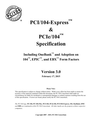
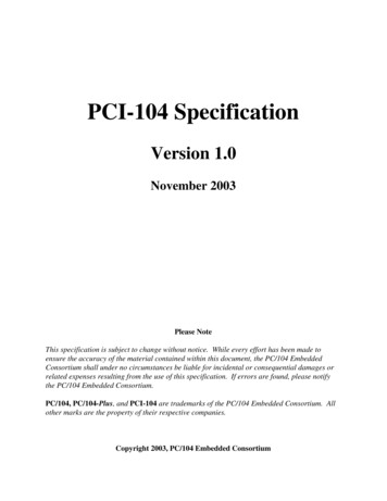
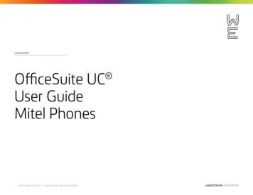
PCAN-PC/104 – User Manual2.1.1InterruptAn interrupt (IRQ) must be assigned to each CAN channel. This isdone with a single jumper on jumper field JP1 for CAN channel 1and jumper field JP2 for CAN channel 2 (latter refers only to theDual Channel model). The PCAN-PC/104 card supports the interrupts 3, 4, 5, 7, 10, 11, 12, and 15. The default setting at delivery forCAN channel 1 is interrupt 10, for CAN channel 2 interrupt 5.Figure 1: Position of the jumper fields for setting the interrupts,JP1 for CAN channel 1 (lower jumper field),JP2 for CAN channel 2 (upper jumper field,Dual Channel model only)It is possible to share the same interrupt between two existing CANchannels. Therefore, you can configure the same interrupt whenusing two PCAN-PC/104 cards in the same computer.Tip: We suggest to configure different interrupts as long asresources allow it and use interrupt sharing only if this is notthe case.9
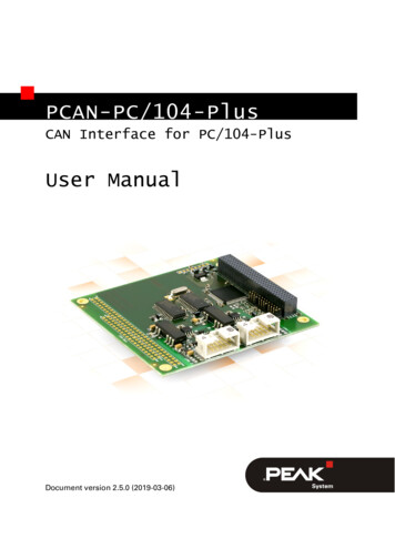
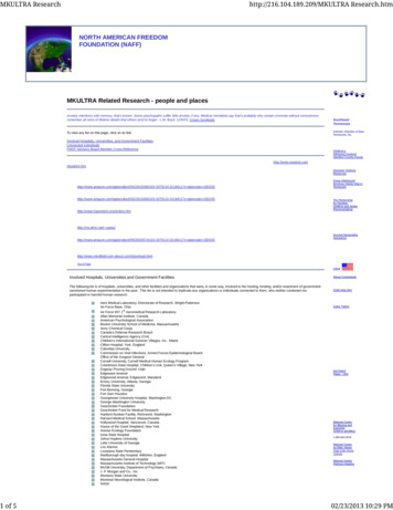
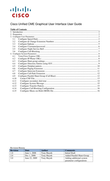
PCAN-PC/104 – User Manual2.1.2I/O Address RangeEach CAN channel must be assigned to an unique I/O address rangein the computer. An address space from 200h up to 39Fh and 3E0hto 3FFh (h hexadecimal) is available. PCAN-PC/104 uses 32 addresses beginning from the configured base address. The configurationis done on jumper field JP3 for CAN channel 1 and jumper field JP4for CAN channel 2 (latter refers only to the Dual Channel model).One or several jumpers are needed for each jumper field.Figure 2: Position of the jumper fields for setting the I/O base addresses,JP3 for CAN channel 1 (left jumper field),JP4 for CAN channel 2 (right jumper field, Dual Channel model only)The following table shows the possible settings. The X stands for aset jumper. The default settings at delivery for CAN channels 1 and2 are highlighted.Continued on the next page10
PCAN-PC/104 – User ManualJumper field JP3/JP4ABCDEXI/O address range200h – 21FhXXXXXXXXXXXXXXXX220h – 23Fh240h – 25FhX260h – 27Fh280h – 29FhXXXXXXXXXXXXXXXXX2A0h – 2BFh2C0h – 2DFhX2E0h – 2FFh300h – 31FhX320h – 33Fh340h – 35FhX360h – 37Fh380h – 39FhXX113E0h – 3FFh
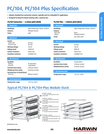
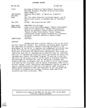
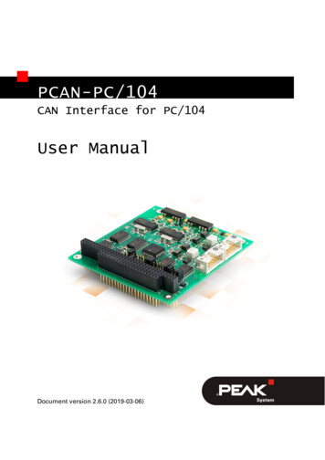
PCAN-PC/104 – User Manual2.2Installing the SoftwareInstall the driver before you install the card.Do the following to install the driver:1.Start Intro.exe from the supplied DVD.The navigation program starts.2.Select in the main menu Drivers and click on Install now.3.Confirm the message of the User Account Control related to"Installer database of PEAK Drivers".The driver setup starts.4.Follow the program instructions until the Costum Setup isdisplayed.Figure 3: Driver selection in the PEAK-Drivers Setup5.Deselect the CAN device drivers and select CAN devicedrivers Non-Plug-and-Play (see Figure 3).12
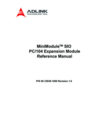
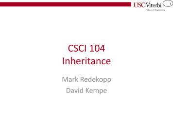
PCAN-PC/104 – User ManualNode: The CAN device drivers Non-Plug-and-Play is onlyavailable under 32-bit Windows. PCAN-PC104 does not workunder 64-bit Windows.6.2.3Follow the further instructions.Installing the HardwareDo the following to install card into the PC/104 stack:Attention! Electrostatic discharge (ESD) can damage or destroycomponents on the card. Take precautions to avoid ESD.1.Shut down the computer.2.Disconnect the computer from the power supply.3.Plug the PCAN-PC/104 card onto a PC/104 connector.4.Interconnect the connector for each CAN channel on thePCAN-PC/104 card (see Figure 4) with the CAN connector ofthe slot bracket using the attached flat cable.5.Reconnect the power supply of the computer.Note: Before switching on the computer, please follow the procedure for modifying the computer's BIOS settings described inthe following section.13
PCAN-PC/104 – User ManualFigure 4: Connectors for the flat cables to the CAN connectors,J3 for CAN channel one (lower position),J4 for CAN channel 2 (upper position, Dual Channel model only)14
PCAN-PC/104 – User Manual2.4Modifying the Computer's BIOS SettingsTo ensure a flawless operation of the PCAN-PC/104 card it is necessary that you adjust settings in the BIOS setup of the computer:Indicate used interruptsDeactivate the APIC modeNote: Due to a diversity of existing BIOS setup versions forcomputers we cannot give detailed instructions here. Insteadwe indicate common setting names.In order to know how to start the computer's BIOS setup pleaseconsult the corresponding documentation. Usually you can enterthe BIOS setup by pressing the Del or F2 key shortly afterswitching on the computer.2.4.1Indicating Used InterruptsBy indicating the interrupts that are set on the PCAN-PC/104 card,you avoid that the corresponding resources are automaticallyassigned to other devices and that this results in conflicts.In the BIOS setup itself you can often find the settings for theinterrupts under a menu item containing the text PnP. For theinterrupt(s) used by PCAN-PC/104 change the setting to Reserved orLegacy ISA.15
PCAN-PC/104 – User Manual2.4.2Deactivating the APIC ModeNote: Do not mix up APIC with ACPI.The APIC mode is a certain type of interrupt management in acomputer.If the APIC mode is active in your computer, you must deactivate itso that the PCAN-PC/104 card can work properly with interrupts.Do the following to determine in Windows if the APIC mode isactive:Open the Windows Device Manager.1.Select the menu entry View Resources by type.2.Open the branch of Interrupt request (IRQ).If entries with interrupt numbers greater than 15 are listed,the APIC mode is active and you must deactivate it.Do the following to deactivate the APIC mode:Important note: When you deactivate the APIC mode in theBIOS setup, it may happen that you must reinstall Windowsafterwards, because it cannot start anymore due to the lowlevel setting.Restart the computer and switch to the BIOS setup.1.Search for the APIC setting and deactivate it.2.Save the changes in the BIOS and quit the BIOS setup.3.If Windows doesn't start properly, reinstall it or perform arepair installation.16
PCAN-PC/104 – User Manual33.1Connecting the CAN BusConnection over D-Sub ConnectorA High-speed CAN bus (ISO 11898-2) is connected to the 9-pinD-Sub connector. The pin assignment corresponds to thespecification CiA 303-1.Figure 5: Pin assignment High-speed CAN(view onto connector of the slot bracket)Low power devices (e.g. bus converters) can be supplied directlywith 5 volts over pin 1 and/or pin 9 of the CAN connector. Pin 1and/or pin 9 are not in use at the delivery state. For moreinformation see the next section 3.2.17
PCAN-PC/104 – User ManualThe pin assignment between the D-Sub port and the 10-pin connector on the PCAN-PC/104 card is as follows:Figure 6: Numbering at the 10-pin connectorAssignmentD-SubPinAssignment1 5 V (optional)12GND63CAN L24CAN H75GND36not connected87not connected48 5 V (optional)99not connected510not connectedTip: You can connect a CAN bus with a different transmissionstandard via a bus converter. PEAK-System offers different busconverter modules (e.g. PCAN-TJA1054 for a Low-speed CANbus according to ISO 11898-3).18
PCAN-PC/104 – User Manual3.1.1Slot Bracket with D-Sub ConnectorsFigure 8: Dual channel slot bracketFigure 7: Single channel slot bracketTo connect a CAN bus to the PCAN-PC/104 card, use the suppliedslot brackets. After you have connected the cables from the slotbracket with the 10-pin sockets, you can connect the CAN busseswith the D-Sub sockets.19
PCAN-PC/104 – User Manual3.2Voltage Supply of External DevicesExternal devices with low power consumption (e.g. bus converters)can be directly supplied via the CAN connector (independently foreach connector on the Dual Channel versions). With a solder bridgeper CAN channel on the PCAN-PC/104 board, a 5-Volt supply canoptionally be routed to pin 1 and/or pin 9 of the D-Sub connector.The opto-decoupled models of the card contain an interconnectedDC/DC converter. Therefore, the current output is limited to about50 mA.Do the following to activate the voltage supply:Risk of short circuit! Solder with great care to avoid unwantedshort circuits on the card.Attention! Electrostatic discharge (ESD) can damage or destroycomponents on the card. Take precautions to avoid ESD.Set the solder bridge(s) on the card according to the desiredsettings.Figure 9 shows the solder field positions on the card. The tablebelow contains the possible settings.20
PCAN-PC/104 – User ManualFigure 9: Position of the solder jumper fields for the 5-Volt supply(JP5 lower position, JP6 upper position)5-Volt supplyD-Sub connectorSolder fieldCAN 1JP5CAN 2JP6Without(Standard)Pin 1Pin 9Pin 1 andpin 9Risk of short circuit! The 5-Volt supply is not protectedseparately. Therefore, turn off the computer before youconnect and disconnect CAN cables or peripheral systems.21
PCAN-PC/104 – User Manual3.33.3.1CablingTerminationA High-speed CAN bus (ISO 11898-2) must be terminated with 120ohms at both ends. The termination prevents interfering signalreflections and ensures the proper operation of the transceivers ofthe connected CAN nodes (CAN interfaces, control devices).The PCAN-PC/104 card does not have an internal termination. Usethe adapter on a terminated CAN bus.3.3.2Example of a ConnectionFigure 10: Simple CAN connectionThis example shows a connection between the PCAN-PC/104 cardand a control unit. The connection cable is terminated with 120ohms at both ends.22
PCAN-PC/104 – User Manual3.3.3Maximum Bus LengthHigh-Speed-CAN networks may have bit rates of up to 1 Mbit/s. Themaximum bus length is primarily depending on the bit rate.The following table shows the maximum CAN bus length at different bit rates:Bit rateBus length1 Mbit/s40 m500 kbit/s110 m250 kbit/s240 m125 kbit/s500 m50 kbit/s1.3 km20 kbit/s3.3 km10 kbit/s6.6 km5 kbit/s13.0 kmThe listed values have been calculated on the basis of an idealizedsystem and can differ from reality.23
PCAN-PC/104 – User Manual4Software and APIThis chapter covers the provided software PCAN-View and theprogramming interface PCAN-Basic.4.1Monitor Software PCAN-ViewPCAN-View is simple Windows software for viewing, transmitting,and logging CAN and CAN FD messages.Note: This chapter describes the use of PCAN-View with a CANadapter.Figure 11: PCAN-View for Windows24
PCAN-PC/104 – User ManualDo the following to start and initialize PCAN-View:1.Open the Windows Start menu and select PCAN-View.The Connect dialog box appears.Figure 12: Selection of the CAN specifichardware and parameters (exemplary)2.Select an interface from the list and continue with step 7.3.If no entry is in the list, press the button Add.The dialog box Add CAN hardware appears.Figure 13: Selection of the hardware4.Select PEAK ISA-CAN SJA.25
PCAN-PC/104 – User Manual5.Enter the port address and the interrupt (see section 2).6.Confirm your input with OK.7.From the drop-down list, select the Bit rate that is used byall nodes on the CAN bus.Tip: You can create custom bit rates by using the button ( ).8.Under Filter settings you can limit the range of CAN IDs tobe received, either for standard frames (11-bit IDs) or forextended frames (29-bit IDs).9.Activate the Listen-only mode if you do not activelyparticipate in the CAN traffic and just want to observe. Thisalso avoids an unintended disruption of an unknown CANenvironment (e.g. due to different bit rates).10. Confirm the settings in the dialog box with OK. The mainwindow of PCAN-View appears (see Figure 14).26
PCAN-PC/104 – User Manual4.1.1Receive/Transmit TabFigure 14: Receive/Transmit tabThe Receive/Transmit tab is the main element of PCAN-View. Itcontains two lists, one for received messages and one for thetransmit messages. The CAN data format is hexadecimal by default.Do the following to transmit a CAN message with PCAN-View:1.Select the menu command Transmit New Message(alternativelyor Ins ).The New Transmit Message dialog box appears.Figure 15: Dialog box new transmit message27
PCAN-PC/104 – User Manual2.Enter the ID, the data Length, and the CAN message Data.Note: With the program version 4 of PCAN-View, the DLC fieldwas renamed to Length. Latter reflects the actual data length.3.Enter a value into the Cycle Time field to choose manuallyor periodically message transmission. Enter a value greaterthan 0 to transmit periodically. Enter the value 0 to transmitonly manually.4.Confirm the entries with OK.The created transmit message appears on theReceive/Transmit tab.5.Trigger selected transmit messages manually with the menucommand Transmit Send (alternatively Space bar). Themanual transmission for CAN messages being transmittedperiodically is carried out additionally.Tip: Using the menu command File Save the current transmitmessages can be saved to a list and loaded for reuse later on.28
PCAN-PC/104 – User Manual4.1.2Trace TabFigure 16: Trace tabOn the Trace tab, the data tracer (data logger) of PCAN-View is usedfor logging the communication on a CAN bus. During this processthe messages are cached in the working memory of the PC.Afterwards they can be saved to a file.The Tracer runs either in linear or in ring buffer mode. The linearbuffer mode stops the Tracer as soon as the buffer is full. The ringbuffer mode overwrites the oldest messages by new ones as soonas the buffer is full.29
PCAN-PC/104 – User Manual4.1.3PCAN-PC/104 TabFigure 17: PCAN-PCI tab (examplary)The PCAN-PC/104-Plus tab contains some detailed informationabout the hardware and driver.4.1.4Status BarFigure 18: Display of the status barThe status bar shows information about the current CANconnection, about error counters (Overruns, QXmtFull) and showserror messages.You can find further information about the use of PCAN-View in thehelp which you can invoke in the program via the Help menu orwith the F1 key.30
PCAN-PC/104 – User Manual4.2Linking Own Programs with PCAN-BasicFigure 19: PCAN-BasicOn the provided DVD, you can find files of the programminginterface PCAN-Basic in the directory branch Develop. This APIprovides basic functi
PC/104 stack with ISA bus (according to the PC/104 specification) Operating system Windows 10, 8.1, 7 (32-bit), or Windows CE 6.x (x86 and ARMv4 processor support), or Linux (32/64-bit) PCAN-PC/104 –