Transcription
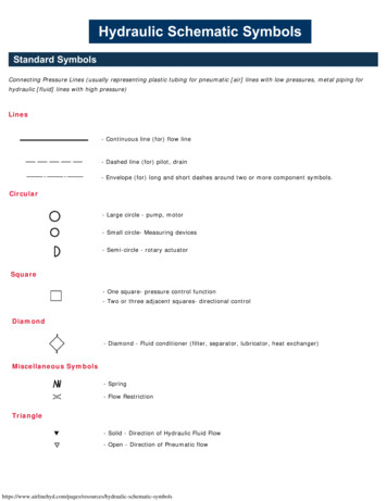
Hydraulic Schematic SymbolsStandard SymbolsConnecting Pressure Lines (usually representing plastic tubing for pneumatic [air] lines with low pressures, metal piping forhydraulic [fluid] lines with high pressure)Lines- Continuous line (for) flow line- Dashed line (for) pilot, drain- Envelope (for) long and short dashes around two or more component symbols.Circular- Large circle - pump, motor- Small circle- Measuring devices- Semi-circle - rotary actuatorSquare- One square- pressure control function- Two or three adjacent squares- directional controlDiamond- Diamond - Fluid conditioner (filter, separator, lubricator, heat exchanger)Miscellaneous Symbols- Spring- Flow RestrictionTriangle- Solid - Direction of Hydraulic Fluid Flow- Open - Direction of Pneumatic raulic-schematic-symbols
Pumps and Compressors(turn rotary torque from an AC or DC electric motor into pressure in a hydraulic or pneumatic system)Fixed Displacement Hydraulic Pump Symbols- Unidirectional- BidirectionalVariable Displacement Hydraulic Pump Symbols- Unidirectional- BidirectionalCompressor symbolMotorsFixed Displacement Hydraulic Motor Symbol- Unidirectional- BidirectionalVariable Displacement Hydraulic Motor Symbol- Unidirectional- BidirectionalPneumatic Motor Symbol- Unidirectional- BidirectionalRotary Actuator Symbol- Hydraulic- s/hydraulic-schematic-symbols
CylindersSingle Acting Cylinder Symbols- Returned by external force- Returned by spring or extended by spring forceDouble Acting Cylinder Symbols- Single piston rod (fluid required to extend and retract)- Double ended piston rodCylinders with Cushions Symbols- Single fixed cushion- Double fixed cushion- Single adjustable cushion- Double adjustable cushionDirectional Control Valve SymbolsDirectional Control Valve (2 ports / 2 positions)- Normally closed directional control valve with 2 ports and 2 finite positions.- Normally open directional control valve with 2 ports and 2 finite positions.Directional Control Valve (3 ports / 2 positions)- Normally closed directional control valve with 3 ports and 2 finite positions.- Normally open directional control valve with 3 ports and 2 finite positions.Directional Control Valve (4 ports / 2 positions)- Directional control valve with 4 ports and 2 finite s/hydraulic-schematic-symbols
Directional Control Valve (4 ports / 3 positions)- Directional control valve with 4 ports and 3 finite positions*-(center position can have various flow paths)Directional control valve (5 ports / 2 positions) Normally a pneumatic valve- Directional control valve with 5 ports and 2 finite positionsDirectional control valve (5 ports / 3 positions) Normally a pneumatic valve- Directional control valve with 5 ports and 3 finite positionsElectro-Hydraulic Servo ValveThe spool positions on these valves is variable allowing for variable flow conditions.- Single-stage direct operation unit which accepts an analog signal and provides a similaranalog fluid power output- Two-stage with mechanical feedback indirect pilot operation unit which accepts an analogsignal and provides a similar analog fluid power ydraulic-schematic-symbols
Control Method - Operator symbols for valvesManual Control- General symbol of a valve's manual operator (without showing the control type)- Pushbutton- Lever- Foot pedalMechanical Valve Control- Plunger or tracer- Spring (used on one side of a valve to hold it in the normally open or normally closed state)- Roller- Roller (one direction only)Electrical/Solenoid Valve Control- Solenoid (the one side's winding shown)Pilot Operation(uses pressure to actuate valve)- Pneumatic actuated pilot- Hydraulic actuated pilotPilot operated two-stage valve(uses a second lesser force to actuate the pilot actuation of the valve)- Pneumatic: Solenoid first stage- Pneumatic: Air pilot second stage- Hydraulic: Solenoid first stage- Hydraulic: Hydaulic pilot second draulic-schematic-symbols
Check valves, Shuttle valves, Rapid Exhaust valves- Check valve symbol-free flow one direction, blocked flow in other direction- Pilot operated check valve symbol, pilot to close- Pilot operated check valve symbol, pilot to openShuttle valve- To isolate one part of a system from an alternate part of circuit.Rapid exhaust valve/Pneumatic- Installed close to an actuator for rapid movement of the actuator.Pressure Control ValvesPressure Relief Valve(safety valve) normally closed- Line pressure is limited to the setting of the valve, secondary part is directed to tank.Proportional Pressure Relief Valve- Line pressure is limited to and proportional to an electronic signalSequence Valve- When the line pressure reaches the setting of the valve, valve opens permitting flow to thesecondary port. The pilot must be externally drained to tank.Pressure Reducing valve (Hydraulic Pressure Regulator)- Pressure downstream of valve is limited to the setting of the draulic-schematic-symbols
Flow Control ValvesThrottle valve- Adjustable output flowFlow Control valves- Flow control valve with fixed output (variations in inlet pressure do not affect rate of flow)- Flow control valve with fixed output and relief port to reservoir with relief for excess flow(variations in inlet pressure do not affect rate of flow)- Flow control valve with variable output- Flow control valve with fixed orifice- Flow control valve with metered flow toward right free flow to left- Flow control valve with pressure compensated flow control fixed output flow regardless ofload- Flow control valve with pressure and temperature compensated- Flow control valve with variable output and relief port to reservoirFlow dividing valve- Flow is divided equally to two outputs.Shut-Off Valve- Shut-Off Valve Simplified symbolAccumulators- Accumulator symbol (Stores Pressure)Reservoir- Reservoir symbol (Holds Fluid medium of your hydraulic-schematic-symbols
Filters, Water Traps, Lubricators and Miscellaneous ApparatusFilter or StrainerWater Trap- With manual drain- With automatic drainedFilter with water trap- With manual drain- Automatic drainAir Dryer- Refrigerant, or chemical removal of water from compressed air lineLubricator- Oil vapor is injected into air lineConditioning unit (FRL, Pressure Regulator)- Compound symbol of filter, regulator, lubricator unit(FRL symbol)- Simplified SymbolHeat Exchangers- Air or water cooled unit designed to remove heat from oil returning to s/hydraulic-schematic-symbols
Standard Symbols Connecting Pressure Lines (usually representing plastic tubing for pneumatic [air] lines with low pressures, metal piping for hydraulic [fluid] lines with high pressure) Lines - Continuous line (for) flow line - Dashed line (for) pilot, drain - Envelope (for) long and short dashes around two or more component symbols. Circular