Transcription
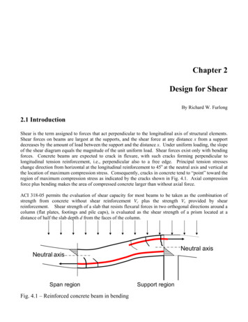
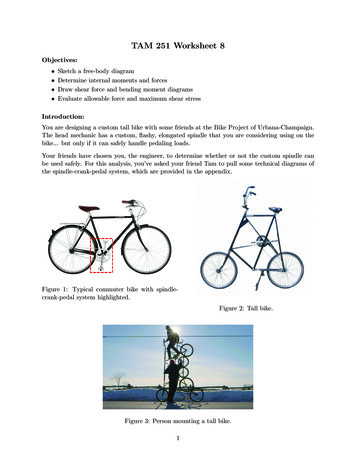
OPTI 222Mechanical Design in Optical EngineeringShear Forces and Bending Moments in BeamsBending Stress:σ MyIMoment of Inertia:Ix Ay2dAIy Ax2dAParallel Axis Theorem:Ix Ixc Ad2Iy Iyc Ad2Beam Classifications:Beams are also classified according to the shape of their cross sections.Shear Force and Bending Moment:When a beam is loaded by forces or couples, internal stresses and strains are created.To determine these stresses and strains, we first must find the internal forces andcouples that act on cross sections of the beam. Consider the following example.43
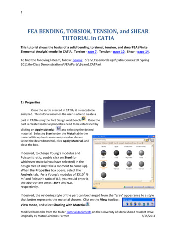
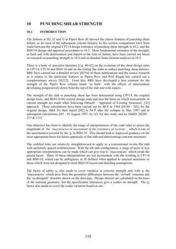
OPTI 222Mechanical Design in Optical EngineeringIt is convenient to reduce the resultant to a shear force, V, and a bending moment, M.Because shear forces and bending moments are the resultants of stresses distributedover the cross section, they are known as stress resultants and in staticallydeterminate beams can be calculated from the equations of static equilibrium.Deformation Sign Conventions:As can be seen in the previous diagram (left hand section vs. right hand section), werecognize that the algebraic sign does not depend on its direction in space, such asupward or downward or clockwise or counterclockwise. The sign depends on thedirection of the stress resultant with respect to the material against which it acts.Shear and Moment Sign ConventionDeformations highly exaggeratedPositive shear forces always deform right hand face downward with respect to the lefthand face. Positive bending moments always elongate the lower section of the beam.44
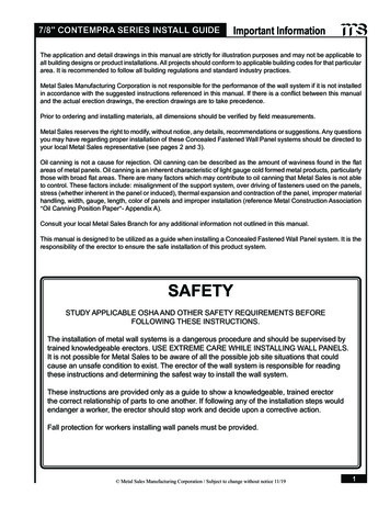
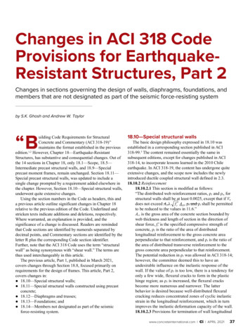
OPTI 222Mechanical Design in Optical EngineeringLoad, Shear Force and Bending Moment Relationships:Consider the following beam segment with a uniformly distributed load with loadintensity q. Note that distributed loads are positive when acting downward and negativewhen acting upward.Summing forces vertically we find:dV qdxThus, the shear force varies with the distance x, and the rate of change (slope) withrespect to x is equal to –q. Also, if q 0, then the shear force is constant.Rearranging and integrating between two points A and B on the beam we have:dV -qdxBB A dV A qdxVB – VA Area of load intensity diagram between A and BSumming moments and discarding products of differentials because they are negligiblecompared to other terms, we have:dM VdxThe above shows that the rate of change of moment with respect to x is equal to theshear force. Also, the above equation applies only in regions where distributed loadsact on the beam. At a point where a concentrated load acts, a sudden change in shearforce results and the derivative dm/dx is undefined.Rearranging and integrating between two points A and B on the beam we have:dM Vdx45
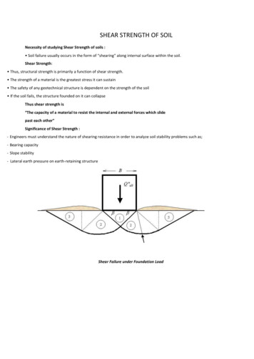
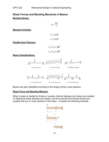
OPTI 222Mechanical Design in Optical EngineeringBB A dM A VdxMB – MA Area of shear force diagram between A and BThe above can be used even when concentrated loads are acting on the beam betweenpoints A and B. However, it is not valid if a couple acts between points A and B.Now consider the following beam segment with a concentrated load, P. Again,concentrated loads are positive when acting downward and negative when actingupward.Summing forces vertically we find:V1 -PThus, an abrupt change occurs in the shear force at a point where a concentrated loadacts. As one moves from left to right through a point of load application, the shear forcedecreases by an amount equal to the magnitude of the downward load.Summing moments we find:M1 P(dx/2) Vdx V1dxSince dx is infinitesimally small, we see that M1 is infinitesimally small. Therefore, weconclude that the bending moment does not change as we move through a point ofconcentrated load application. Recall that dm/dx V. Since the shear force changes atthe point of load application, we conclude that the rate of change dm/dx decreasesabruptly by an amount equal to P.Finally, we consider the following beam segment with a concentrated couple, M0.Counterclockwise couples are considered to be positive and clockwise couples areconsidered to be negative.Summing moments and disregarding terms that contain differentials, we have:M1 -M046
OPTI 222Mechanical Design in Optical EngineeringThe previous equation shows that there is an abrupt decrease in the bending moment inthe beam due to the applied couple, M0, as we move from left to right through the pointof load application.In summary:Distributed loadsShear force slope (dV/dx) -qVB – VA Area of load intensity diagram between A and BMoment slope (dM/dx) VMB – MA Area of shear force diagram between A and BConcentrated loadsShear force slope (dV/dx) 0At load application V1 -PMoment slope (dM/dx) V (not valid at load application)Concentrated loadsMoment slope (dM/dx) decreases by PMB – MA Area of shear force diagram between A and BConcentrated CouplesCauses an abrupt change in bending momentShear and Bending Moment Diagrams:The loading on most beams is such that the stress resultant on planes perpendicular tothe axis of the beam consists of a shear force, V, and a bending moment, M. Indetermining beam responses, it is very convenient, if not essential, to first determine theshear and bending moment diagrams.The basic procedure for determining the shear and moment diagrams is to determinethe values of V and M at various locations along the beam and plotting the results.In doing so, we will determine critical sections within the beam. A critical section is onewhere a critical or maximum stress occurs. Section of Maximum Shear – Since theshear, V, at any transverse section of the beam is the algebraic sum of the transverseforces to the left of the section, the shear, in most cases, can be evaluated at a glance.Section of Maximum Moment – It can be shown mathematically, that when the shearforce is zero or changes sign; the bending moment will be either a maximum or relativemaximum.47
Concentrated Couples Causes an abrupt change in bending moment Shear and Bending Moment Diagrams: The loading on most beams is such that the stress resultant on planes perpendicular to the axis of the beam consists of a shear force, V, and a bending moment, M. In