Transcription
Changes in ACI 318 CodeProvisions for EarthquakeResistant Structures, Part 2Changes in sections governing the design of walls, diaphragms, foundations, andmembers that are not designated as part of the seismic force-resisting systemby S.K. Ghosh and Andrew W. Taylor“Building Code Requirements for StructuralConcrete and Commentary (ACI 318-19)”maintains the format established in the previousedition.1,2 However, Chapter 18—Earthquake-ResistantStructures, has substantive and consequential changes. Out ofthe 14 sections in Chapter 18, only 18.1—Scope, 18.5—Intermediate precast structural walls, and 18.9—Specialprecast moment frames, remain unchanged. Section 18.11—Special precast structural walls, was updated to include asingle change prompted by a requirement added elsewhere inthe chapter. However, Section 18.10—Special structural walls,underwent quite extensive changes.Using the section numbers in the Code as headers, this anda previous article outline significant changes in Chapter 18relative to the previous edition of the Code. Underlined andstricken texts indicate additions and deletions, respectively.Where warranted, an explanation is provided, and thesignificance of a change is discussed. Readers are remindedthat Code sections are identified by numerals separated bydecimal points, and Commentary sections are identified by theletter R plus the corresponding Code section identifier.Further, note that the ACI 318 Code uses the term “structuralwall” as being synonymous with “shear wall.” The terms arethus used interchangeably in this article.The previous article, Part 1, published in March 2021,covers changes through Section 18.8, focused primarily onrequirements for the design of frames. This article, Part 2,covers changes in:18.10—Special structural walls;18.11—Special structural walls constructed using precastconcrete;18.12—Diaphragms and trusses;18.13—Foundations; and18.14—Members not designated as part of the seismicforce-resisting system. 18.10—Special structural wallsThe basic design philosophy expressed in 18.10 wasestablished in a corresponding section published in ACI318-99.3 The content remained essentially the same insubsequent editions, except for changes published in ACI318-14, to incorporate lessons learned in the 2010 Chileearthquake. In ACI 318-19, the content has undergone quiteextensive changes, and the scope now includes the newlyintroduced ductile coupled structural wall defined in 2.3.18.10.2 Reinforcement18.10.2.1 This section is modified as follows:“The distributed web reinforcement ratios, ρℓ and ρt, forstructural walls shall be at least 0.0025, except that if Vudoes not exceed Acvλ f c′ Acv, ρℓ and ρt shall be permittedto be reduced to the values in 11.6.”Acv is the gross area of the concrete section bounded byweb thickness and length of section in the direction ofshear force, fc′ is the specified compressive strength ofconcrete, ρℓ is the ratio of the area of distributedlongitudinal reinforcement to the gross concrete areaperpendicular to that reinforcement, and ρt is the ratio ofthe area of distributed transverse reinforcement to thegross concrete area perpendicular to that reinforcement.The potential reduction in ρℓ was allowed in ACI 318-14;however, the committee deemed this to have anundesirable influence on the inelastic response of thewall. If the value of ρℓ is too low, there is a tendency foronly a few wide, flexural cracks to form in the plastichinge region; as ρℓ is increased, the flexural cracksbecome more numerous and narrower. The latterbehavior is desired because well-distributed flexuralcracking reduces concentrated zones of cyclic inelasticstrain in the longitudinal reinforcement, which in turnimproves the inelastic deformation capacity of the wall.18.10.2.3 Provisions for termination of wall longitudinalwww.concreteinternational.com Ci APRIL 202137
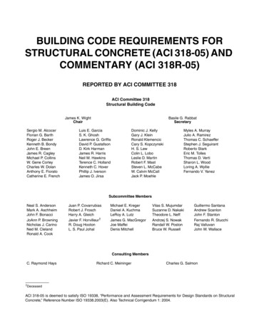
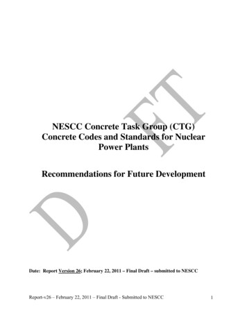
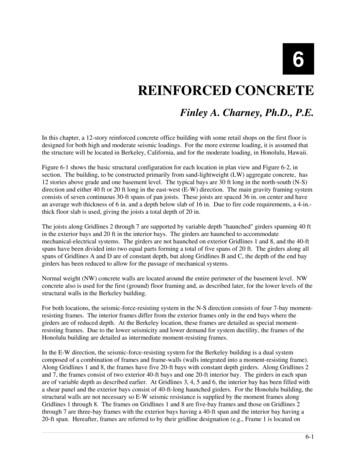
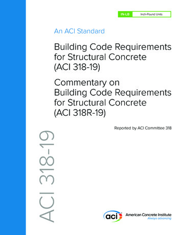
reinforcement are modified to address the perceivedconservatism of the ACI 318-14 provision for low-risewalls and to address inconsistencies between engineeringpractice and the ACI 318-14 requirements. A newprovision, summarized in Fig. 1, is intended to allowmore frequent termination of longitudinal (vertical)reinforcement over the height of tall walls. ACI 318-14specified that longitudinal bars be extended at least 0.8ℓwabove the point at which they are no longer required toresist flexure. This was cumbersome. For example, a 30 ftlong (horizontal width) wall required a bar extension of24 ft, which is the typical height of two stories. Aprovision was also added to prohibit lap splices ofboundary longitudinal reinforcement in the regionimmediately above and below the critical section. Testresults4 have demonstrated that lap splices at the criticalsection tend to significantly reduce wall inelasticdeformation capacity.The text in this section was modified as follows:“Reinforcement in structural walls shall be developed orspliced for fy in tension in accordance with 25.4, 25.5, and(a) through (cd):(a) Longitudinal reinforcement shall extend beyond thepoint at which it is no longer required to resist flexure byleast 0.8ℓw, except at the top of a wallExcept at the top of a wall, longitudinal reinforcementshall extend at least 12 ft above the point at which it is nolonger required to resist flexure but need not extend morethan ℓd above the next floor level.(b) [Unchanged from ACI 318-14]Fig. 1: Termination of wall flexural reinforcement andlap-splicing limitations at critical section38APRIL 2021 Ci www.concreteinternational.com(c) Lap splices of longitudinal reinforcement withinboundary regions shall not be permitted over a heightequal to hsx above, and ℓd below, critical sections whereyielding of longitudinal reinforcement is likely to occuras a result of lateral displacements. The value of hsx neednot exceed 20 ft. Boundary regions include those withinlengths specified in 18.10.6.4(a) and within a length equalto the wall thickness measured beyond the intersectingregion(s) of connected walls.(d) [Unchanged from (c) in ACI 318-14]R18.10.2.3 is revised to note that “Bar terminationsshould be accomplished gradually over a wall height andshould not be located close to critical sections whereyielding of longitudinal reinforcement is expected.Strain hardening of reinforcement results in spread ofplasticity away from critical sections as lateraldeformations increase.”18.10.2.4 This new section provides requirements forlongitudinal reinforcement at wall ends (Fig. 2).Minimum reinforcement ratio; bar extension beyond thecritical, yielding section; and termination limits aredefined. Commentary Section R18.10.2.4 notes that therequirements are intended to address two primary issues.First, if insufficient longitudinal reinforcement isprovided in concrete walls, the cracking moment mayexceed the nominal moment strength of the wall andsudden loss of strength and failure may occur when thewall first cracks. Additionally, the tension force generatedby the longitudinal reinforcement at the ends of the wallmay be insufficient to develop well-distributed secondaryflexural cracks in the surrounding concrete, resulting ininelastic reinforcement strains being concentrated at onlya limited number of cracks and potentially leading toreinforcement fracture.Wall deformation capacity depends on the distribution ofcracks within the plastic hinge region. Well-distributedflexural cracks over the plastic hinge region generallyresult in large plastic deformations prior to strength loss.Observations following the 1985 Chile earthquake5 andthe 2010-2011 New Zealand earthquakes6 indicate thatthe relatively slender walls in multi-story buildings withlight longitudinal reinforcement at the wall ends formed aFig. 2: Various wall configurations showing end regions requiring longitudinalreinforcement per 18.10.2.4(a) (ACI 318-19, Fig. R18.10.2.41)
limited number of cracks, or a single crack, in the plastichinge region. The lack of distributed cracks led to theconcentration of the inelastic deformation capacity in asignificantly reduced plastic hinge length, and this waspresumed to be the cause of the observed fractures oflongitudinal reinforcement.The requirements in this provision are unlikely to impactconstruction significantly in the United States, as thegeneral practice is to use relatively few walls that tend tobe heavily reinforced at the wall ends. Note that thisprovision is not specific to the “boundary elements ofspecial structural walls” defined in 18.10.6. It appliesto longitudinal reinforcement located at the wall endsin general.18.10.2.5 This new section requires that reinforcement incoupling beams be developed or spliced for fy in tensionin accordance with 25.4, 25.5, and (a) and (b):“(a) If coupling beams are reinforced according to18.6.3.1 [as special moment frame beams], thedevelopment length of longitudinal reinforcement isrequired to be 1.25 times the values calculated for fy intension.(b) If coupling beams are reinforced according to18.10.7.4, the development length of diagonalreinforcement is required to be 1.25 times the valuescalculated for fy in tension.”18.10.3 Design forcesAs with previous editions, ACI 318-19 requires beam andcolumn sections of special moment frames to be designedfor the largest shear Ve that can develop at such a beam orcolumn section (see 18.6.5.1 and 18.7.6.1.1, respectively).In no case can Ve be smaller than the factored shearobtained at that section from an analysis of the structureunder code-prescribed seismic forces.ACI 318-14 (and prior editions of ACI 318), however,required a special shear wall section to be designed forthe factored shear Vu obtained at the section from analysisof the structure that includes the shear wall undercode-prescribed seismic forces. No attempt was made todetermine the largest shear that can develop at the shearwall section. This has now changed in ACI 318-19.18.10.3.1 This new section requires consideration offlexural overstrength. For flexure-controlled walls,flexural overstrength reduces collapse risk and mayimprove performance; however, also for flexurecontrolled walls exhibiting nonlinear response, sheardemand is determined in part by flexural strength. Thus,flexural overstrength contributes to increased sheardemand and is considered in defining shear demand usedin design by ACI 318-19. Many other design codes,standards, and guides around the world, including CSAA23.3,7 require flexural overstrength to be accounted forin design.Multiple studies have investigated, and multiple designcodes, standards, and guides around the world specify,dynamic amplification of shear demand (due to highermode effects) in concrete walls. Research by Pugh et al.8showed, using nonlinear dynamic analysis of idealizedwalled buildings ranging in height from 6 to 24 stories,that the dynamic amplification factor ωv can range from1.1 to 2.5. Pugh et al.8 showed also that dynamicamplification equations included in the New Zealanddesign standard9 as well as those recommended bySEAOC,10 which define dynamic amplification on thebasis of building height, provide fairly consistent, modestunderprediction of dynamic amplification.ACI 318-19 requires cross sections of a special shear wallto be designed for an amplified shear Ve equal to the Vuobtained from analysis of the structure under codeprescribed seismic forces, amplified by an overstrengthfactor Ωv and a dynamic amplification factor ωv:Ve ΩvωvVu 3VuThe values for Ωv and ωv vary with hwcs/ℓw, where hwcs isthe height of the entire structural wall above the criticalsection for flexural and axial loads. Per Table 18.10.3.1.2,if hwcs/ℓw 1.5, Ωv Mpr/Mu 1.5 for the loadcombination producing the largest value of Ωv. For hwcs/ℓw 1.5, Ωv 1.0. Further, for hwcs/ℓw 2.0, ωv 1.0. Forhwcs/ℓw 2.0, ωv varies with the number of stories ns.ωv 0.9 ns/10 for ns 6ωv 1.3 ns/30 1.8 for ns 6Note that ns 0.007hwcs, with hwcs in units of inches.This is a very important code change that will have a majorimpact on the design of flexure-controlled shear walls.18.10.4 Shear strength18.10.4.6 This new section makes it clear that therequirements of 21.2.4.1 are not applicable for walls orwall piers designed according to the displacementbased approach of 18.10.6.2. Section 21.2.4.1 requiresthat the strength reduction factor φ used for shearstrength in members designed to resist earthquakeeffects must be 0.6, rather than the usual 0.75, if thenominal shear strength of the member is less than theshear corresponding to the nominal flexural strength ofthe member.18.10.6 Boundary elements of special structural walls18.10.6.2 Item (b) in this section is new, and it introducesa separate wall drift capacity check that is in addition tothe drift check required by ASCE/SEI 7.11Abdullah and Wallace12 created a database of 164 tests ofwalls with special boundary elements and determined thatdrift capacity is primarily a function of three ratios: ℓw/b,c/b, and Ve/(Acv f c′ ), where b is the wall thickness and cis the neutral axis depth. Based on a regression analysis ofthe data, the mean drift capacity for walls with specialboundary elements is given by:δℓ 0.015where δc is the wall displacement capacity at the top ofwww.concreteinternational.com Ci APRIL 202139
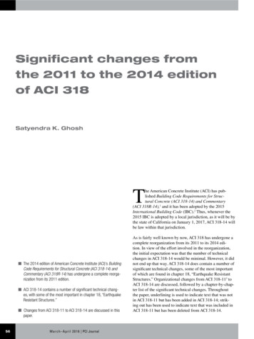
the wall. Item (b) in 18.10.6.2requires that the wall drift demand,estimated as 1.5δu/hwcs, must be lessthan or equal to the wall driftcapacity determined using theaforementioned equation. Thisprovision results in roughly a 10%probability of strength loss fordesign earthquake-level shaking.The new provision also includes asimplified approach to satisfying thedrift capacity check by including aminimum wall compression zonewidth. Assuming Ve/(8Acv f c′ ) 1.0and δu/hwcs 0.015, the requirementthat 1.5δu/hwcs δc/hwcs can bereduced to this simple constraint:b 0.025cℓwIn general, the new provision willrequire redesign of walls with largevalues of ℓw/b ( 15 to 20), largevalues of c/b ( 3 to 4), and highshear demands as indicated byVu/(Acv f c′ ) ( 6 to 8). Theprovision also applies to coupledwalls, and it may require the use ofthicker wall piers for coupled walls.18.10.6.4 Configurationrequirements for transversereinforcement in boundary elementsand webs were modified in ACI318-19 (Fig. 3). The changes wereprompted by observations followingrecent earthquakes as well as theresults of laboratory testing. Thelength of a hoop leg must notexceed two times the boundaryelement thickness; and adjacenthoops must overlap at least 6 in. ortwo-thirds the boundary elementthickness, whichever is smaller.Also, for a distance above andbelow the critical section equal tothe greater of ℓw and Mu/4Vu, webvertical reinforcement must beenclosed by the corner of a hoop orby a crosstie with a seismic hook ateach end.18.10.6.5 This section providesrequirements on horizontal andtransverse reinforcement in walls inwhich special boundary elementsare not required by 18.10.6.2 and18.10.6.3. It has been updated to40account for Grade 80 and Grade100 longitudinal reinforcement. Ifthe reinforcing ratio at the wallboundary exceeds 400/fy, thevertical spacing of transversereinforcement at the wall boundaryis required to be in accordance witha new Table 18.10.6.5(b),reproduced herein as Table 1. Notethat the spacing has not changed forwalls with Grade 60 primaryflexural reinforcement.18.10.9 Ductile coupled wallsThe prevalent seismic forceresisting system used for modernhigh-rise concrete buildings in highseismic regions comprisesreinforced concrete core walls.Current design practice uses theprovisions of ACI 318 for design ofthe materials (Chapter 18) and theseismic design coefficients fromASCE/SEI 711 (responsemodification coefficient R 5 or 6,for example) for calculation of thedesign lateral loads based on theductility of the force-resistingsystem. The special reinforcedconcrete shear wall has historicallyincluded all shear wall variations.That is, differentiation in behavioris not recognized between slenderversus squat walls, flanged versusrectangular walls, and coupledversus cantilever walls. As of the2019 edition of ACI 318, a newsystem definition has been createdin 2.3—Terminology, to recognizethe ductile coupled structural wall(DCSW). The definition for aDCSW system refers to Section18.10.9, where the requirements forthe system are given.The performance objective of theDCSW system is to dissipate mostof the energy in the couplingbeams—analogous to the strongcolumn weak beam performanceFig. 3: Configurations of boundary transverse reinforcement and web crossties (ACI 318-19,Fig. R18.10.6.4a)APRIL 2021 Ci www.concreteinternational.com
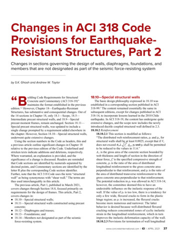
Table 1:objective in moment frames.Maximum vertical spacing of transverse reinforcement at wall boundaryStudies were conducted to identify(ACI 318-19, Table 18.10.6.5(b)1)system characteristics that led tocoupling beam energy dissipationGrade of primaryof no less than 80% of total systemflexuralMaximum vertical spacing ofenergy dissipation under riskreinforcing barTransverse reinforcement requiredtransverse reinforcement*targeted maximum considered6dbearthquake (MCER) groundWithin the greater of ℓw and Mu/4VuLesser of:motions. In these studies, nonlinearabove and below critical sections†6 in.60response history analyses were8dbconducted using spectrally matchedOther locationsLesser of:8 in.ground motion records on a varietyof coupled shear wall archetypes.5dbWithin the greater of ℓw and Mu/4VuLesser of:Archetypes ranged from five toabove and below critical sections†6 in.8050 stories in height, and they6dbaccommodated a range ofOther locationsLesser of:6 in.longitudinal reinforcement ratios in4dbWithin the greater of ℓw and Mu/4Vuthe coupling beams as well as theLesser of:above and below critical sections†shear walls. Results of these6 in.100analyses are presented in Fig. 4.6dbOther locationsLesser of:The x-axis represents the aspect6 in.(clear span to total depth) ratio of*In this table, db is the diameter of the smallest primary flexural reinforcing bar.the coupling beams, with D†Critical sections are defined as locations where yielding of longitudinal reinforcement is likely todesignating diagonally reinforcedoccur as a result of lateral displacements.coupling beams and M indicatingcoupling beams detailed as momentframe beams. The y-axis is the percentage of total systemenergy dissipation that occurs in the coupling beamsalone. The analyses show that coupling beams withaspect ratios ranging from 2 to 5 tend to be effective atdissipating most of the system energy.The analyses show that the primary characteristics of aDCSW system are geometry based. Squat walls are toostiff to allow sufficient story drift for coupling beams tobehave inelastically, so each wall in a DCSW systemneeds to have a total-height-to-length ratio of at least 2.0.Squat coupling beams overcouple the seismic forceresisting system, leading to significant energy dissipationin the wall piers rather than the coupling beams. Thus,each coupling beam in a DCSW system needs to have alength-to-total-depth ratio of at least 2.0. Very slendercoupling beams, designated as having aspect ratiosgreater than 5.0, are too weak to contribute sufficientFig. 4: Energy dissipated by coupling beams. Labels “low,” “mod.,”hysteretic energy dissipation. Thus, such beams areand “high” refer to the relative quantities of flexural reinforcement inthe beams (Courtesy of Magnusson Klemencic Associates)allowed in no more than 10% of all floor levels of thebuilding. Further, the flexural reinforcement in couplingbeams conforming to these geometric constraints is18.11—Special structural walls constructedrequired to develop 1.25fy at each end to dissipate theusing precast concreteintended hysteretic energy. This requirement is intended18.11.2 Generalto preclude the use of fixed-pinned coupling beams that18.11.2.1 While special structural walls constructed usingmight be considered where one wall pier has insufficientprecast concrete are required to comply with thewidth to develop the coupling beam reinforcement.provisions of 18.10—Special structural walls, the newLastly, the noted requirements of the DCSW system arerequirement for minimum longitudinal reinforcementin addition to existing requirements for special structural(18.10.2.4) at the wall ends does not apply for precastwalls and coupling beams.www.concreteinternational.com Ci APRIL 202141
walls where deformation demands are concentrated at thepanel joints.18.12—Diaphragms and trusses18.12.7 Reinforcement18.12.7.4 In ACI 318-14, this section required Type 2splices where mechanical splices are used to transferforces between the diaphragm and the vertical elementsof the seismic force-resisting system. ACI 318-19 retainsthe same requirement for Grade 60 reinforcement andadds that Grade 80 and Grade 100 reinforcement mustnot be mechanically spliced for this purpose.18.12.7.5 Table 20.2.2.4(a) permits the maximum designyield strength of reinforcement to be 80,000 psi forportions of a collector—for example, at and near criticalsections. To control diaphragm cracking over the lengthof the collector, the average stress in the collector needsto be limited. This new section therefore requireslongitudinal reinforcement for collectors to beproportioned such that the average tensile stress overlength (a) or (b) does not exceed ffy, where the value of fyis limited to 60,000 psi:(a) Length between the end of a collector and location atwhich transfer of load to a vertical element begins.(b) Length between two vertical elements.18.12.11 Precast concrete diaphragmsTwo subsections are new to ACI 318-19:18.12.11.1 Diaphragms and collectors constructed usingprecast concrete members with composite topping slaband not satisfying 18.12.4 [interface between topping slaband precast diaphragm clean, free of laitance, andintentionally roughened], and untopped precast concretediaphragms, are permitted provided they satisfy therequirements of ACI 550.5.13 Cast-in-place noncompositetopping slab diaphragms are required to satisfy 18.12.5and 18.12.6 [minimum thickness of diaphragms].18.12.11.2 Connections and reinforcement at joints usedin the construction of precast concrete diaphragmssatisfying 18.12.11.1 are required to have been tested inaccordance with ACI 550.4.1418.13—FoundationsThis section has greatly expanded from ACI 318-14 to ACI318-19, because the seismic design provisions for deepfoundations have been imported from IBC15 and ASCE/SEI 7.11 These changes are too voluminous to be detailed inthis article.18.14—Members not designated as part of theseismic force-resisting system18.14.2 Design actions18.14.2.1 This section has been modified as shown:“Members not designated as part of the seismic-forceresisting system shall be evaluated for gravity loadcombinations of (1.2D 1.0L 0.2S) or 0.9D, whichever42APRIL 2021 Ci www.concreteinternational.comis critical, 5.3 including the effect of vertical groundmotion acting simultaneously with the designdisplacement δu. The load factor on the live load, L, shallbe permitted to be reduced to 0.5 except for garages,areas occupied as places of public assembly, and all areaswhere L is greater than 100 lb/ft2.”The load combinations of ACI 318-14 thus haveeffectively become:(1.2 0.2SDS)D 1.0L 0.2S) or(0.9 – 0.2SDS)D.If gravity frame members remain elastic (Mu Mn, Vu Vn) under the imposed design earthquake displacementsδu, then the sections to be satisfied are: 18.14.3.2(a) forbeams, 18.14.3.2(c) for highly axially loaded columnsthat may fail in compression, and 18.14.3.2(b) for othercolumns.18.14.3 Cast-in-place beams, columns, and joints18.14.3.2 Modifications have been made to items (a), (b),and (c), and item (d) has been added:“(a) Beams shall satisfy 18.6.3.1. Transversereinforcement shall be provided throughout the length ofthe beam at a spacing not to exceed d/2. Where factoredaxial force exceeds Ag fc′/10, transverse reinforcementshall be hoops satisfying 18.7.5.2 at a spacing so,according to 18.14.3.2(b) not to exceed the lesser of 6dbof the smallest enclosed longitudinal bar and 6 in.(b) Columns shall satisfy 18.7.4.1, 18.7.5.2, and 18.7.6.The maximum longitudinal spacing of hoops shall be sofor the full column length. Spacing so shall not exceed thelesser of six diameters of the smallest longitudinal barenclosed and 6 in. Spiral reinforcement satisfying 25.7.3or hoop reinforcement satisfying 25.7.4 shall be providedover the full length of the column with spacing not toexceed the lesser of 6db of the smallest enclosedlongitudinal bar and 6 in. Transverse reinforcementsatisfying 18.7.5.2(a) through (e) shall be provided over alength ℓo, as defined in 18.7.5.1, from each joint face.(c) Columns with factored gravity axial forces exceeding0.35Po shall satisfy 18.14.3.2(b) and 18.7.5.7. Theminimum amount of transverse reinforcement providedshall be, one-half of that required by 18.7.5.4 and spacingshall not exceed so for the full column length. forrectilinear hoops, one-half the greater of Table 18.7.5.4parts (a) and (b) and, for spiral or circular hoops, one-halfthe greater of Table 18.7.5.4 parts (d) and (e). Thistransverse reinforcement shall be provided over a lengthℓo, as defined in 18.7.5.1, from each joint face.(d) Joints shall satisfy Chapter 15.”18.14.5 Slab-column connectionsThis section has been modified in significant ways. Onlythe post-tensioned slab provisions are new. The otherchanges essentially represent reorganization.18.14.5.1 “For slab-column connections of two-way slabswithout beams, slab shear reinforcement satisfying therequirements of 18.14.5.3 and either 8.7.6 or 8.7.7 shall
be provided at any slab critical section defined in 22.6.4.1for the following conditions:(a) Nonprestressed slabs where x/hsx 0.035 – (1/20)(vuvg/fvc)(b) Unbonded post-tensioned slabs with fpc in eachdirection meeting the requirements of 8.6.2.1, where x/hsx 0.040 – (1/20)(vuvg/fvc)The load combinations to be evaluated for vuv shall onlyinclude those with E. The value of ( x/hsx) shall be takenas the greater of the values of the adjacent stories aboveand below the slab-column connection, vc shall becalculated in accordance with 22.6.5 and, for unbondedpost-tensioned slabs, the value of Vp shall be taken as zerowhen calculating vc.”Note that the text following “ defined in 22.6.4.1” in theprevious version of 18.14.5.1 has been deleted from thissection, and a portion has been included in 18.14.5.3 asindicated in the following description.18.14.5.2 Note that while this section includesrequirements from 18.14.5.1 in the previous edition, therequirements in (b) are new.“The shear reinforcement requirements of 18.14.5.1 neednot be satisfied if (a) or (b) is met:(a) Δx/hsx 0.005 for nonprestressed slabs(b) Δx/hsx 0.01 for unbonded post-tensioned slabs withfpc in each direction meeting the requirements of 8.6.2.1.”18.14.5.3 “ if x/hsx 0.035 – (1/20)(vuvg/fvc). Requiredslab shear reinforcement shall provide vs 3.5 f c′ at theslab critical section and shall extend at least four times theslab thickness from the face of the support adjacent to theslab critical section. The shear reinforcement requirementsof this provision shall not apply if Δx/hsx 0.005.The value of (Δx/hsx) shall be taken as the greater of thevalues of the adjacent stories above and below the slabcolumn connection. vc shall be calculated in accordancewith 22.6.5. vug is the factored shear stress on the slabcritical section for two-way action due to gravity loadswithout moment transfer.”Concluding RemarksACI 318-19 Chapter 18—Earthquake-Resistant Structures,includes many substantive changes. In Part 1, we summarizedthe changes in Sections 18.2—General, plus changes inSections 18.3 through 18.8, which govern the design ofordinary and intermediate moment frames as well as the designof beams, columns, and joints of special moment frames.In this, Part 2, we discussed the latter sections of Chapter18. Key changes include:ASTM A706 Grade 80 and Grade 100 bars are nowpermitted to resist bending moments, shear forces, and axialforces in special structural walls, including coupling beamsand wall piers. Section 18.10—Special structural walls, hasundergone by far the most substantive changes.The corresponding section in ACI 318-9516 underwentprofound changes in ACI 318-99 but remained essentiallyunchanged through ACI 318-11.17 Significant changes weremade in ACI 318-14 in view of observations made after theChile earthquake of 2010 and the Christchurch, NewZealand, earthquakes of 2010-2011. Further major changeswere made in ACI 318-19 in view of observations made afterrecent earthquakes and tests. The biggest change is in theshear design of shear walls, which is now much moreconservative. It is believed that this change will have abeneficial impact on the performance of concrete structureswith seismic force-resisting systems comprising specialstructural walls.AcknowledgmentsPro Dasgupta, S.K. Ghosh Associates LLC (SKGA), Palatine, IL, USA,provided a thorough review that significantly enhanced this article.Bodhi Rudra, SKGA, provided much valuable help in putting togetherthe manuscript.References1. ACI Committee 318, “Building Code Requirements for StructuralConcrete (ACI 318-19) and Commentary (ACI 318R-19),” AmericanConcrete Institute, Farmington Hills, MI, 2019, 624 pp.2. ACI Committee 318, “Building Code Requirements for StructuralConcrete (ACI 318-14) and Commentary (ACI 318R-14),” AmericanConcrete Institute, Farmington Hills, MI, 2014, 519 pp.3. ACI Committee 318, “Building Code Requirements for StructuralConcrete (ACI 318-99) and Commentary (ACI 318R-99),” AmericanConcrete Institute, Farmington Hills, MI, 1999, 391 pp.4. Aaleti, S.; Brueggen, B.L.; Johnson, B.; French, C.E.; andSritharan, S., “Cyclic Response of Reinforced Concrete Walls withDifferent Anchorage Details: Experimental Verification,” Journal ofStructural Engineering, ASCE, V. 139, No. 7, July 2013, pp. 1181-1191.5. Wood
ACI 318-14 (and prior editions of ACI 318), however, required a special shear wall section to be designed for the factored shear V u obtained at the section from analysis of the structure that includes the shear wall under code-prescribed seismic forces. No attempt was made to determine the