Transcription
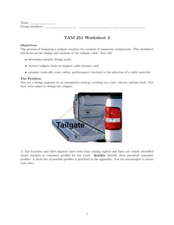
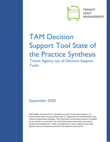
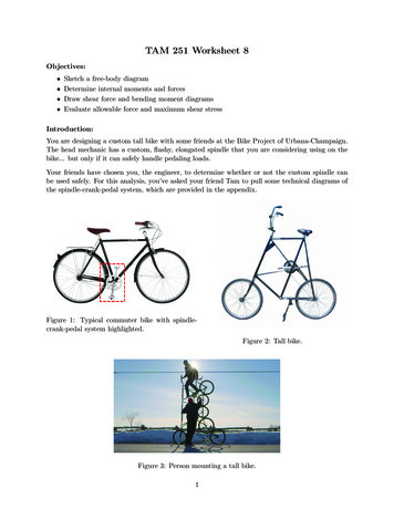
TAM 251 Worksheet 8Objectives: Sketch a free-body diagramDetermine internal moments and forcesDraw shear force and bending moment diagramsEvaluate allowable force and maximum shear stressIntroduction:You are designing a custom tall bike with some friends at the Bike Project of Urbana-Champaign.The head mechanic has a custom, flashy, elongated spindle that you are considering using on thebike. but only if it can safely handle pedaling loads.Your friends have chosen you, the engineer, to determine whether or not the custom spindle canbe used safely. For this analysis, you’ve asked your friend Tam to pull some technical diagrams ofthe spindle-crank-pedal system, which are provided in the appendix.Figure 1: Typical commuter bike with spindlecrank-pedal system highlighted.Figure 2: Tall bike.Figure 3: Person mounting a tall bike.1
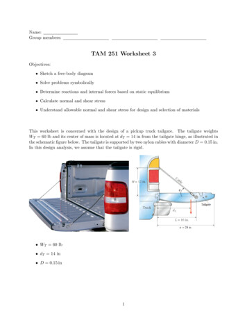
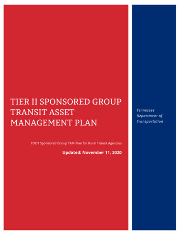
AppendixThe resultant load from pedaling is represented as a concentrated force P at the center of the pedal.Assume there is no force applied to the other pedal (not shown).PPedaldcCranka 70 mmb 25 mmbc 9.5 mmLd 40 mmaSpindleL 170 mmFigure 5: Dimensions.Figure 4: The spindle-crank-pedal system.Assume that the bearings are aligned and set in the frame of the bike, keeping the spindle inequilibrium while exerting only forces (not moments). Therefore, as illustrated in Figure 7, thebike spindle can be represented as a beam with reaction forces at the bearings, forces and momentsapplied at cross-section A (where the crank attaches to the spindle), and a chain tension pullingon the chain igure 6: Crank-pedal free-body diagram.Figure 7: Spindle free-body diagram.2
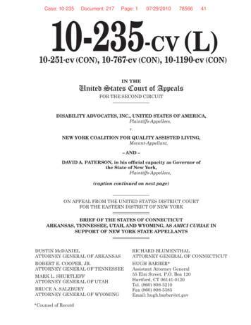
1) As shown in the crank-pedal free-body diagram (Figure 6), pedaling forces bend and twist thespindle. Determine the internal moments and forces at the cross-section A (MA , TA and VA ) as afunction of the force P . Note: We are interested in the internal shear force, moment, and torqueof the spindle, which has been cut out of this diagram to expose the surface where it meets thecrank.2)PDetermine the lower chain tension F1 and the upper chain tension F2 via the equilibrium equation( M )Cx axis 0. Assume that the chain ring has radius R 75 mm and lies in the same planeas the right bearing (cross-section C). Note: You will need to make one additional assumptionregarding the chain tensions.3
3) Detemine the reactions at the bearings (RBy , RBz , RCy , RCz ) as a function of the force P bywriting and solving equilibrium force and moment equations.4) Draw the shear force Vy and bending moment Mz diagrams for the spindle from cross-section A(x 0) to cross-section C (x 95 mm).4
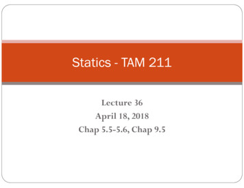
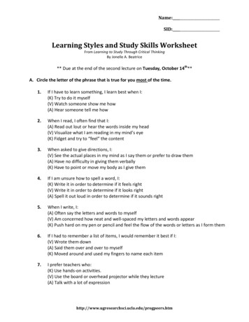
5) The spindle cross-section illustrated below is located at x 40 mm. The spindle is hollow withouter diameter do 27 mm and inner diameter di 21 mm. Assume that P 200 N to determinethe normal stresses at points H, K and L.yzHKL5
6) The spindle is made of steel with yielding strength σY 400 MPa. Determine the maximumforce Pmax that can be applied to the pedal if we want to apply a factor of safety against yieldingequal to 2.7) Use the maximum force Pmax that you obtained in part (6) to evaluate the maximum shearstress due to torsion.6
TAM 251 Worksheet 8 Objectives: Sketch a free-body diagram Determine internal moments and forces Draw shear force and bending moment diagrams Evaluate allowable force and maximum shear stress Introduction: You are designing a custom tall bike with some friends at the Bike Project of Urbana-Champaign. The head mechanic has a custom,