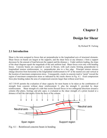
Transcription
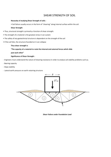
SHEAR STRENGTH OF SOILNecessity of studying Shear Strength of soils : Soil failure usually occurs in the form of “shearing” along internal surface within the soil.Shear Strength: Thus, structural strength is primarily a function of shear strength. The strength of a material is the greatest stress it can sustain The safety of any geotechnical structure is dependent on the strength of the soil If the soil fails, the structure founded on it can collapseThus shear strength is“The capacity of a material to resist the internal and external forces which slidepast each other”Significance of Shear Strength :- Engineers must understand the nature of shearing resistance in order to analyze soil stability problems such as;- Bearing capacity- Slope stability- Lateral earth pressure on earth-retaining structureShear Failure under Foundation Load
Slope Stability Failure as an Example of Shearing Along Internal SurfaceAt failure, shear stress along the failure surface reaches the shearThus shear strength of soil is“The capacity of a soil to resist the internal and external forces which slide past eachother”Shear Strength in Soils :- The shear strength of a soil is its resistance to shearing stresses.- It is a measure of the soil resistance to deformation by continuous displacement of itsindividual soil particles.- Shear strength in soils depends primarily on interactions between particles.-Shear failure occurs when the stresses between the particles are such that theyslide or roll past each other
Components of shear strength of soilsSoil derives its shear strength from two sources:– Cohesion between particles (stress independent component) Cementation between sand grains Electrostatic attraction between clay particles– Frictional resistance and interlocking between particles (stress dependentcomponent)Cohesion :Cohesion (C), is a measure of the forces that cement particles of soils
Internal Friction :Internal Friction angle (f), is the measure of the shear strength of soils due to friction
Angle of ReposeAngle of Repose determined by:Particle size (higher for large particles)Particle shape (higher for angular shapes)Shear strength (higher for higher shear strength)Stresses:Gravity generates stresses (force per unit area) in the ground at different points.Stress on a plane at a given point is viewed in terms of two components:Normal stress (σ) : acts normal to the plane and tends to compress soilgrains towards each other (volume change)Shear stress (τ): acts tangential to the plane and tends to slide grains relative to each other (distortion and ultimatelysliding failure).LECTURE 31Factors Influencing Shear Strength:The shearing strength, is affected by:– soil composition: mineralogy, grain size and grain size distribution, shape ofparticles, pore fluid type and content, ions on grain and in pore fluid.– Initial state: State can be describe by terms such as: loose, dense, overconsolidated,normally consolidated, stiff, soft, etc.– Structure: Refers to the arrangement of particles within the soil mass; themanner in which the particles are packed or distributed. Features such aslayers, voids, pockets, cementation, etc, are part of the structure.Mohr-Coulomb Failure Criteria:This theory states that a material fails because of a critical combination of normal stress and shear stress, and not fromtheir either maximum normal or shear stress alone.
Direct Shear Test:Dry sand can be conveniently tested by direct shear tests. The sand is placed in a shear box that is split into twohalves . A normal load is first applied to the specimen. Then a shear force is applied to the top half of the shearbox to cause failure in the sand. The normal and shear stresses at failure are
LECTURE 33Triaxial TestsTriaxial compression tests can be conducted on sands and clays shows a schematic diagram of the Triaxial test arrangement.Essentially, it consists of placing a soil specimen confined by a rubber membrane in a Lucite chamber. An all-round confiningpressure (σ3) is applied to the specimen by means of the chamber fluid (generally water or glycerin). An added stress (Δσ) canalso be applied to the specimen in the axial direction to cause failure (Δσ Δσf at failure). Drainage from the specimen can beallowed or stopped, depending on the test condition. For clays, three main types of tests can be conducted with Triaxialequipment:Triaxial test:1. Consolidated-drained test (CD test)2. Consolidated-undrianed test (CU test)3. Unconsolidated-undrained test (UU test) MajorPrincipal effective stress σ3 Δσf σ1 σ′1 Minor Principaleffective stress σ3 Δσ′3Changing σ3 allows several tests of this type to be conducted on various clay specimens. The shear strengthparameters (c and ϕ) can now be determined by plotting Mohr’s circle at failure, as shown in figure and drawing a commontangent to the Mohr’s circles. This is the Mohr-Coulomb failure envelope. (Note: For normally consolidated clay, c 0). At failureFor consolidated-undrained tests, at failure,Major Principal total stress σ3 Δσf σ1Minor principal total stress σ3Major principal effective stress (σ3 Δσf) uf σ′1
Minor principal effective stress σ3 uf σ′3Changing σ3 permits multiple tests of this type to be conducted on several soil specimens. The total stress Mohr’s circles atfailure can now be plotted, as shown in figure , and then a common tangent can be drawn to define the failure envelope. Thistotal stress failure envelope is defined by the equations ccu σtanϕcuWhere ccu and ϕcu are the consolidated-undrained cohesion and angle of friction respectively (Note: ccu 0 for normallyconsolidated clays)Similarly, effective stress Mohr’s circles at failure can be drawn to determine the effective stress failure envelopes.They follow the relation expressed in equation .For unconsolidated-undrained triaxial testsMajor principal total stress σ3 Δσf σ1Minor principal total stress σ3
The total stress Mohr’s circle at failure can now be drawn, as shown in figure. For saturated clays, the value of σ1 σ3 Δσf is aconstant, irrespective of the chamber confining pressure, σ3.The tangent to these Mohr’s circles will be a horizontal line, calledthe ϕ 0 condition. The shear stress for this condition isWhereB Skempton′s pore pressure parameterSimilarly,the pore pressure ud is the result of added axial stress, Δσ, soud A ΔσWhereA Skempton′s pore pressure parameterHowever,Δσ σ1 σ3Combining equations givesu ua ud Bσ3 Aσ1 σ3The pore water pressure parameter B in soft saturated soils is 1, sou σ3 A(σ1 σ3)The value of the pore water pressure parameter A at failure will vary with the type of soil. Following is a general range of thevalues of A at failure for various types of clayey soil encountered in nature.
UNCONFINED COMPRESSION TESTThe unconfined compression test is a special type of unconsolidated-undrained Triaxial test in which the confining pressureσ3 0, as shown in figure. In this test an axial stress, Δσ, is applied to the specimen to cause failure (that is, Δσ Δσf). Thecorresponding Mohr’s circle is shown in figure . Note that, for this case, u
Unconfined compression test: (a) soil specimen; (b) Mohr’s circle for the test; (c) variation of qu with the degree of saturationMajor principal total stress Δσf quMinor principal total stress 0The axial stress at failure, Δσf qu is generally referred to as the unconfined compression strength. The shear strengthof saturated clays under this condition (ϕ 0,The unconfined compression strength can be used as an indicator for the consistency of clays. Unconfined compression testsare sometimes conducted on unsaturated soils. With the void ratio of a soil specimen remaining constant, the unconfinedcompression strength rapidly decreases with the degree of saturation shows an unconfined
Vane Shear Test:Fairly reliable results for the undrained shear strength, c,, (S : 0 concept), of very soft to medium cohesive soils may be obtaineddirectly from vane shear tests. The shear vane usually consists of four thin, equal-sized steel plates welded to a steel torque rod.First, the vane is pushed into the soil. Then torque is applied at the top of the torque rod to rotate the vane at a uniform speed.A cylinder of soil of height ft and diameter r/ will resist the torque until the soil fails. The undrained shear strength of the soilcan be calculated as follows. If I is the maximum torque applied at the head of the torque rod to cause failure, it should beequal to the sum of the resisting moment of the shear force along the side surface of the soil cylinder (M.) and the resistingmoment of the shear force at each end (M,,)l. Triangular. Shear strength mobilization is c,, at the periphery of the soil cylinder and decreases lineaarly to zero at the center.2, IJni.form.S hears trengthm obilization is constant ( that is, c)f room the periphery to the center of the soil cylinder.3. Parabolic. Shear strength mobilization is c,, at the periphery of the soil cylinder and dccreases parabolically to zero at the center.These variations in shear strength mobilization are shown in Figure .In general, the torque, I at failure can be expressed as
(a) resisting moment of shear force; (b) variations in shear strength mobilization
Thus shear strength of soil is “The capacity of a soil to resist the internal and external forces which slide past each other” Shear Strength in Soils : - The shear strength of a soil is its resistance to shearing stresses. - It is a measure of the soil resistance to deformation by continuous displa