Transcription
INSIDE:MultiMedia CDSolidWorks 2011 Tutorialwith MultiMedia CDAn audio/visualpresentation of thetutorial projectsA Step-by-Step Project Based Approach Utilizing 3D Solid ModelingUsing over 50 feature and sketch toolsDavid C. Planchard & Marie P. Planchard CSWPIncluded in this book:150 PAGES OFSDCPUBLICATIONSSolidWorksCertificationExamStudy Materialwww.SDCpublications.comSchroff Development Corporation
Visit the following websites to learn more about this book:
Chapter 1LINKAGE AssemblyLINKAGE AssemblyCourtesy ofGears Educational Systems & SMCCorporation of AmericaBelow are the desired outcomes and usage competencies based on the completion ofChapter 1.Desired Outcomes:Usage Competencies: Understand the SolidWorks default UserInterface. Establish a SolidWorks session. Create 2D sketch profiles on the correctSketch plane.o FLATBAR Apply the following 3D features: ExtrudedBoss/Base, Extruded Cut and LinearPattern.Create an assembly: Understand the Assembly toolbar.o LINKAGE assembly Insert components into an assembly. Apply the following Standard mates:Concentric, Coincident and Parallel.Create three parts:o AXLEo SHAFT-COLLAR PAGE 1 - 1
Linkage AssemblySolidWorks 2011 TutorialNotes:PAGE 1 - 2
SolidWorks 2011 TutorialLinkage AssemblyChapter 1 - LINKAGE AssemblyChapter ObjectiveSolidWorks is a design software application used to model and create 2D and 3Dsketches, 3D parts, 3D assemblies and 2D drawings. The chapter objective is to provide acomprehensive understanding of the SolidWorks default User Interface andCommandManager: Menu bar toolbar, Menu bar menu, Drop-down menu, Contexttoolbar / menus, Fly-out FeatureManager, System feedback, Confirmation Corner,Heads-up View toolbar and an understanding of Document Properties.Obtain the working familiarity of the following SolidWorks sketch and feature tools:Line, Circle, Centerpoint Straight Slot, Smart Dimension, Extruded Boss/Base, ExtrudedCut and Linear Pattern.Create three individual parts: AXLE, SHAFT-COLLAR and FLATBAR.Create the assembly, LINKAGE using the three created parts and the downloadedsubassembly - AirCylinder from the CD in the book.On the completion of this chapter, you will be able to: Start a SolidWorks session and navigate through the SolidWorks (UI) andCommandManager. Set units and dimensioning standards for a SolidWorks document. Generate a 2D sketch and identify the correct Sketch plane. Add and modify sketch dimensions. Create a 3D model. Understand and apply the following SolidWorks features:o Extruded Boss/Base, Extruded Cut and Linear Pattern Insert the following Geometric relations: Vertical, Horizontal, Coincident, MidPoint,Parallel and Equal. Download an assembly into SolidWorks and create an assembly. Understand the Assembly toolbar. Apply the following Standard mates: Coincident, Concentric and Parallel.PAGE 1 - 3
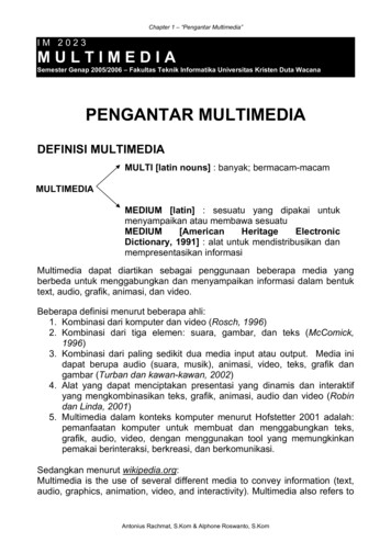
Linkage AssemblySolidWorks 2011 TutorialChapter OverviewSolidWorks is a 3D solid modeling CADsoftware package used to produce and modelparts, assemblies, and drawings.AXLESHAFTCOLLARSolidWorks provides design software to create3D models and 2D drawings.Create three parts in this chapter: AXLE SHAFT-COLLAR FLATBARFLATBARDownload the AirCylinder assemblyfrom the enclosed CD.The AirCylinder assembly is alsoavailable from the internet.Combine the created parts and thedownloaded AirCylinder assembly tocreate the LINKAGE assembly.AirCylinder assemblyIllustrations in the book display the defaultSolidWorks user interface for 2011 SP1.0.Every license of SolidWorks 2011,contains a copy of SolidWorksSustainabilityXpress. SolidWorksSustainabilityXpress calculates environmentalimpact on a model in four key areas: CarbonFootprint, Energy Consumption, AirAcidification and Water Eutrophication.Material and Manufacturing process region andTransportation Use region are use as inputvariables.PAGE 1 - 4LINKAGE assembly
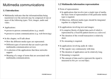
SolidWorks 2011 TutorialLinkage AssemblyAXLE PartThe AXLE is a cylindrical rod. The AXLEsupports the two FLATBAR parts.Tangent Edges and origins are displayedfor educational purposes in this book.AXLEFLATBARThe AXLE rotates about its axis. Thedimensions for the AXLE are determined from othercomponents in the LINKAGE assembly.AxisStart a new SolidWorks session. Create the AXLE part.Apply features to create parts. Features are the buildingblocks that add or remove material.tool from the FeaturesUtilize the Extruded Boss/Basetoolbar to create a Boss-Exturde1 feature. The ExtrudedBoss/Base feature adds material. The Base feature (BossExtrude1) is the first feature of the part. The Base feature is thefoundation of the part. Keep the Base feature simple!The Base feature geometry for the AXLE is a simple extrusion.How do you create a solid Extruded Boss/Base feature for theAXLE? Select the Front Plane as the Sketch plane. Sketch a circular 2D profile on the Front Plane, centered atthe Origin as illustrated. Apply the Extruded Boss/Base Feature. Extend theprofile perpendicular ( ) to the Front Plane.OriginUtilize symmetry. Extrude the sketch with the MidPlane End Condition in Direction 1. The ExtrudedBoss/Base feature is centered on both sides of the FrontPlane.Start a SolidWorks session. The SolidWorks applicationis located in the Programs folder.OriginPAGE 1 - 5
Linkage AssemblySolidWorks 2011 TutorialSolidWorks displays the Tip of the Day box. Read the Tip of the Day to obtain additionalknowledge on SolidWorks.from theCreate a new part. Select File, New from the Menu bar toolbar or click NewMenu bar menu. There are two options for new documents: Novice and Advanced. Selectthe Advanced option. Select the default Part document.Activity: Start a SolidWorks SessionStart a SolidWorks 2011 session.1)Click Start from the Windows Taskbar.2)Click All Programs3)Click the SolidWorks 2011 folder.4)Click the SolidWorks 2011 application. The SolidWorks program windowopens. Note: Do not open a document at this time.5)If you do not see the below screen, click the SolidWorks Resourcestab onthe right side of the Graphics window location in the Task Pane as illustrated.If available, double-click the SolidWorks 2011 icon on the WindowsDesktop to start a SolidWorks session.The book is written using SolidWorks Office 2003 on Windows XPProfessional SP3.0 with a Windows Classic desktop theme.Read the Tip of the Day dialog box.PAGE 1 - 6
SolidWorks 2011 TutorialLinkage AssemblyActivity: Understand the SolidWorks User Interface and CommandManagerMenu bar toolbarSolidWorks 2011 (UI) isdesign to make maximum useof the Graphics window area. The defaultMenu bar toolbar contains a set of the mostfrequently used tool buttons from the Standardtoolbar. The available tools are: New- Creates a new document, Open- Opens an- Saves an active document, Print- Prints an activeexisting document, Savedocument, Undo- Reverses the last action, Select- Selects Sketch entities,components and more, Rebuild- Rebuilds the active part, assembly or drawing, File- Shows the summary information on the active document, OptionsPropertiesChanges system options and Add-Ins for SolidWorks.-Menu bar menuClick SolidWorks in theMenu bar toolbar todisplay the Menu bar menu. SolidWorks provides a Context-sensitive menu structure.The menu titles remain the same for all three types of documents, but the menu itemschange depending on which type of document is active.Example: The Insert menu includes features in part documents, mates in assemblydocuments, and drawing views in drawing documents. The display of the menu is alsodependent on the workflow customization that you have selected. The default menu itemsfor an active document are: File, Edit, View, Insert, Tools, Window, Help and Pin.The Pinoption displays the Menu bar toolbar and the Menu bar menu asillustrated. Throughout the book, the Menu bar menu and the Menu bar toolbar is referredas the Menu bar.Until a file is converted to the current version ofSolidWorks and saved, a warning icon is displayed on theSave tool as illustrated.PAGE 1 - 7
Linkage AssemblySolidWorks 2011 TutorialDrop-down menuSolidWorks takes advantage of the familiar Microsoft Windows user interface. Communicate with SolidWorks either through the;Drop-down menu, Pop-up menu, Shortcut toolbar, Fly-out toolbaror the CommandManager.A command is an instruction that informs SolidWorks to performa task. To close a SolidWorks drop-down menu, press the Esckey. You can also click any other part of the SolidWorks Graphicswindow, or click another drop-down menu.Right-clickRight-click in the: Graphics window, FeatureManager, or Sketchto display a Context-sensitive toolbar. If you are in the middle of acommand, this toolbar displays a list of options specifically relatedto that command.Press the s key to view/access previous command tools in theGraphics window.Consolidated toolbarSimilar commands are grouped in the CommandManager.Example: Variations of the Rectangle sketch tool are grouped in asingle fly-out button as illustrated.If you select the Consolidated toolbar button without expanding: For some commands such as Sketch, the most commonlyused command is performed. This command is the first listed andthe command shown on the button. For commands such as rectangle, where you may want torepeatedly create the same variant of the rectangle, the last usedcommand is performed. This is the highlighted command whenthe Consolidated toolbar is expanded.System feedbackSolidWorks provides system feedback by attachinga symbol to the mouse pointer cursor. The systemfeedback symbol indicates what you are selecting orwhat the system is expecting you to select.PAGE 1 - 8FaceEdgeDimensionVertex
SolidWorks 2011 TutorialLinkage AssemblyAs you move the mouse pointer acrossyour model, system feedback is providedto you in the form of symbols, riding nextto the cursor arrow as illustrated.Confirmation CornerWhen numerous SolidWorks commands are active, a symbol or a setof symbols are displayed in the upper right hand corner of theGraphics window. This area is called the Confirmation Corner.When a sketch is active, the confirmation corner box displays twosymbols. The first symbol is the sketch tool icon. The second symbolis a large red X. These two symbols supply a visual reminder that youare in an active sketch. Click the sketch symbol icon to exit the sketchand to saves any changes that you made.When other commands are active, the confirmation corner boxprovides a green check mark and a large red X. Use the green checkmark to execute the current command. Use the large red X to cancelthe command.Heads-up View toolbarSolidWorks provides the user withnumerous view options from theStandard Views, View and Heads-upView toolbar. The Heads-up Viewtoolbar is a transparent toolbar that isdisplayed in the Graphics windowwhen a document is active.You can hide, move or modify theHeads-up View toolbar. To modifythe toolbar: right-click on a tool andselect or deselect the tools that youwant to display. The following viewsare available: Note: Views aredocument dependent.For an activepart or assemblydocumentFor an activedrawingdocument Zoom to Fit: Zooms themodel to fit the Graphics window. : Zooms to theZoom to Areaareas you select with a bounding box. Previous View Section View: Displays a cutaway of a part or assembly, using one or more crosssection planes.: Displays the previous view.PAGE 1 - 9
Linkage AssemblySolidWorks 2011 Tutorial View Orientation: Provides the ability to select a vieworientation or the number of viewports. The available optionsare: Top, Isometric, Trimetric, Dimetric, Left, Front, Right,Back, Bottom, Single view, Two view - Horizontal, Two view Vertical, Four view. : Provides the ability to display theDisplay Stylestyle for the active view. The available options are:Wireframe, Hidden Lines Visible, Hidden Lines Removed,Shaded, Shaded With Edges. Hide/Show Items: Provides the ability to select itemsto hide or show in the Graphics window. Note: Theavailable items are document dependent. Edit Appearance: Provides the ability to applyappearances from the Appearances PropertyManager. : Provides the ability toApply Sceneapply a scene to an active part or assemblydocument. View the available options. : Provides the ability toView Settingselect the following: RealView Graphics,Shadows in Shaded Mode and Perspective. Rotate : Provides the ability to rotate adrawing view. 3D Drawing View : Provides the ability to dynamicallymanipulate the drawing view to make a selection.To deactivate the reference planes for an active document, clickView; uncheck Planes from the Menu bar. To deactivate the grid,click Options , Document Properties tab. Click Grid/Snaps;uncheck the Display grid box.Modify the Heads-up View toolbar. Press the space key. TheOrientation dialog box is display. Click the New Viewtool. TheName View dialog box is displayed. Enter a new named view. ClickOK. The new view is displayed in the Heads-up View toolbar.PAGE 1 - 10
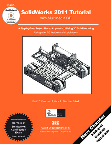
SolidWorks 2011 TutorialLinkage AssemblySolidWorks CommandManagerThe SolidWorks CommandManager is a Context-sensitive toolbar that automaticallyupdates based on the toolbar you want to access. By default, it has toolbars embedded init based on your active document type. When you click a tab below theCommandManager, it updates to display that toolbar. Example, if you click the Sketchtab, the Sketch toolbar is displayed. The default Part tabs are: Features, Sketch, Evaluate,DimXpert and Office Products.Below is an illustrated CommandManager for a default Part document.If you have SolidWorks, SolidWorks Professional, orSolidWorks Premium, the Office Products tab appears on theCommandManager as illustrated.New for 2011 - select the Add-In directly from the OfficeProducts tab.To customize the CommandManager, right-click on a tab andselect Customize CommandManager.PAGE 1 - 11
Linkage AssemblySolidWorks 2011 TutorialBelow is an illustrated CommandManager for the default Drawing document. The defaultDrawing tabs are: View Layout, Annotat
Download the AirCylinder assembly from the enclosed CD. The AirCylinder assembly is also available from the internet. Combine the created parts and the downloaded