Transcription
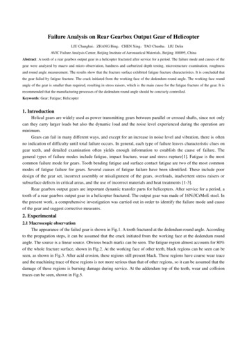
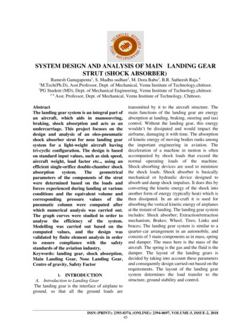
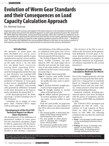
TECHNICALEvolution of Worm Gear Standardsand their Consequences on LoadCapacity Calculation ApproachDr. Michel OctrueBeginning with a brief summary and update of the latest advances in the calculation methods for wormgears, the author then presents the detailed approach to worm gear geometry found in the revised ISOTR 10828. With that information, and by presenting examples, these new methods are explained, as aretheir possibilities for addressing the geometrical particularities of worm gears and their impact upon thebehavior and load capacity of a gearset under working conditions based on ISO TR 14521 — Methods Band C. The author also highlights the new possibilities offered on that basis for the further evolution ofload capacity calculation of a worm gearset based on load and contact pressure distribution.IntroductionThe geometry of worm gears hasbeen developed o v e r m a n y y e a r sby internal convention specific to gearmanufacturers, and by various authorswho have contributed reference bookson the topic ( R e f s . 1 – 6), but thereh a s not always b e e n c o n s e n s u samong them regarding definit i o n s / t e r m i n o l o g y . There was aneed for homogeneity and the first stepin that direction was standard DIN3975 — published in 1960. To furthercontribute to a better approach in theprediction of behavior of worm gearsin first service, standardized methodshave been published concurrentlywith geometrical definitions includedin the same document as the load capacity calculation document (Ref. 7).At the international level, the Working Group 7 of Sub-Committee One ofISO TechnicalCommittee 60 in charge of wormgears (ISO TC60/SC1/WG7) beganwork on this topic in 1992.Development of the First ISOTechnical Report on WormGear GeometryThe development of the unification ofgeometrical symbols of worm gears,and the associated calculation, beganin 1992 in conjunction with the discussions over the concept of the load capacity of worm gears. It has since beendecided to first develop a documentwith definitions of the different profilesof cylindrical worm gears that servesas the basis of the next step in creatingthe load capacity ISO documents.The Technical Report ISO TR 10828/Worm P rofiles Geometry was published in 1997. The main target was todescribe and provide the basic equations of the axial profiles of the threadprofiles for the five most common typesof worms (Fig. 1):Type A: Straight-sided axial profileType C: Concave axial profile formedby machining with a convex circular profile disc-type cutter or grinding wheelType I: Involute helicoid, straight generatrix in base tangent planesType N: Straight profiles in normalplane of thread space helixType K: Milled helicoid generated bybi-conical grinding wheel or milling cutter, convex profiles in axialplanesFrom the axial profile, its projectionin different plane was also defined inthis TR in order to be able to determine(Fig. 2): The normal profile, to determine theshape of the flying cutting tool formachining the worm wheel The rack profile in offset planesused to calculate the conjugateworm wheel profiles The transverse profile of the wormwhich can be used for the control(The decision of the WG to not include in this document all the geometrical definitions of worm gears is because similar work on a load capacitycalculation standard is in progress, including the minimum set of geometrical relations requested by this seconddocument.)Evolution of Load CapacityCalculation Methods for WormGearsDue to the complex geometry, the loadcapacity of worm gears has been developed over a long period on standardsbased on industrial experience withempirical factors with two main criteria: contact pressure (some time calledwear) and bending of threads.Analytical methods, including geometrical aspects, have been developedwith the power of computers, and thefirst version of DIN 3996 was publishedin 1998.ISO TC60/SC1/WG7 developed andpublished the ISO TR 14521 — Calculation of L oad Capacity of WormGears — in 2010; this standard isbased on DIN 3996. The followingconditions that can limit the rated loadcapacity are: Wear: such damage usually appearson the tooth flanks of bronze wormwheels Pitting: this form of damage mayappear on the flanks of wormwheel teeth. Its development isstrongly influenced by the loadThis paper was first presented at the 2013 VDI International Conference on Gears, Technical University of Munich, Garching, Germany,and is reprinted here with VDI permission.36Power Transmission EngineeringSEPTEMBER 2014]————WWW.POWERTRANSMISSION.COM
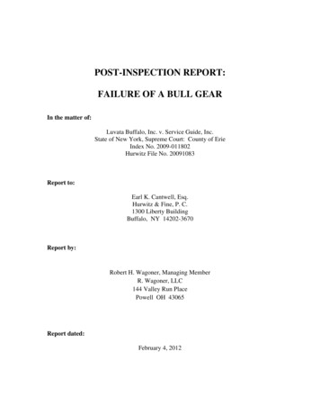
A ProfileI ProfileK ProfileC ProfileN ProfileFigure 1 Cylindrical worm gear profiles.transmitted and the load-sharingconditions. Tooth breakage: shear failure ofworm wheel teeth or worm threadscan occur when teeth become thindue to wear or overload. Worm thread and worm shaftbreakage: shaft breakage can occuras a result of bending fatigue oroverload. Worm shaft deflection: excessivedeformation under load modifyingcontact pattern between worm andworm wheel. Scuffing: this form of damage oftenappears suddenly and is stronglyinfluenced by transmitted load,sliding velocities and the conditionsof lubrication Working temperature: whenexcessively high workingtemperature leads to accelerateddegradation of the worm gearlubricant.The calculation of load capacity isbased on the following criteria, whichare linked as follows: Criteria for pitting and criteriafor worm shaft deflection areindependent of othersFigure 2 Contact line on a worm wheel and Section A-A normal to the contact line 1. Criteria for wear and criteria fortooth breakage of worm wheel aredependent because the reductionof worm wheel tooth thickness bywear is taken into account for thecalculation of shear stress at toothrootCriteria for wear is function of oilfilm thickness, which depends on oilfilm temperature, so the calculation ofdifferent type of power losses in orderto determine the wheel bulk temperature, is the first step for wear calculationSEPTEMBER 2014In order to isolate the influence ofgeometry on the zone of contact andthe lines of contact, it has been definednon-dimensional parameters:pm* mean Hertzian stressh* mean lubricant film thicknesss* mean slip path.To determine those non-dimensional parameters TR 14521 defines twomethods:Method C: Based on simplified formulae which are given in the TRand which are available in a cerPower Transmission Engineering37
TECHNICALFigure 3 A, I and N profiles generated by a helical cylindrical displacement of a straight line.Figure 4 C and K profiles grinding wheel parameters.tain range of basic geometrical parameter range: the equations applyto flank form I but can also be usedin an approximate manner for toothforms K, A and N. The approximation formulae for C-worm drives arederived from Bibliography (25) andfrom operational experience. Theapproximation equations indicatedin 7.3.1, 7.3.2 and 7.3.3 apply to Iworm drives with αn 18. 22 , x2 0.5. 1, ham1 ham2 2 mx1, C-wormdrives with αn 20. 24 , x2 0. 0.5,ham1 ham2 2 mx1 and ρ/mn 5. 7.Method B: based on numerical determination with a detailed studyin each point of the lines of contactin terms of radius of curvature, sumsliding velocity in the normal direction, and mean local sliding path(Fig. 2).How to Define a Standard forGeometry of a Worm GearTaking into account the complex geometry of worm gearing, and in order to apply Method B for all typesof worm profiles, it was important toclarify the application of Method Band to enlarge the scope of TR 10828to the definition of a complete standardon the geometry of worm gear.Method B must also be used because the use of geometrical parameters like normal pressure angle, addendum coefficient, face width andexternal diameter for worm wheelevolve in a significant range from o n egear manufacturer to another, and a r enot sufficiently explained inMethod C.So the revision of ISO 10828 waslaunched at the end of 2010 with a newFigure 5 Pitch surfaces and offset plane.38Power Transmission EngineeringSEPTEMBER 2014]————WWW.POWERTRANSMISSION.COM
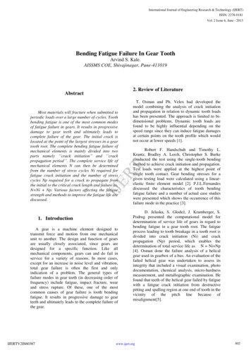
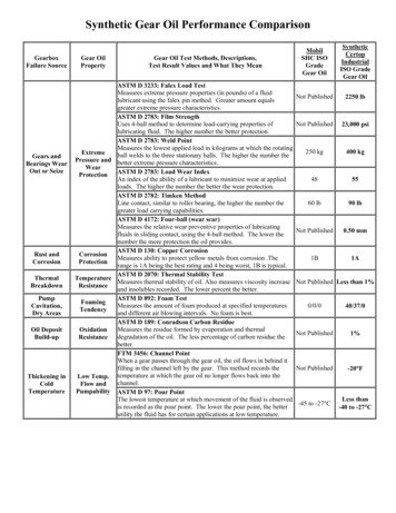
tittle — “Worm Profiles and G ear MeshG eometry.”Content of Revised ISO 10828First of all, the different geometrical parameters for the worm and theworm wheel, as well as for the pitchsurfaces defined previously in theISO/TR 14521, have been revised andincluded in the revision. The goal is todelete those definitions in the futurerevision of ISO/TR 14521 in order tohave a unique definition.The main improvement concernsthe following points:1. Worm profiles have been split intotwo families, and axial worm profiles have been defined:a. Profiles generated by a helical cylindrical displacement of a straightline that is available for A, I andN profiles (Fig. 3): For thoset h r e e profiles a general equation has been set up; each profileis accessible by using the correctcoefficients. The main parameterof those profiles is the radius inthe axial profile of the worm.b. Equations for profiles generated bya profiled disk grinding wheel, asfor K and C profiles (Fig. 4): Eachprofile is accessible by the equation of the grinding wheel profile.The main parameter of those profiles is the radius of the axial profileof the grinding wheel. There is nota direct relation to obtain the axialprofile of the worm.2. In order to define the conjugate profile of the worm — i.e. — the wormwheel profile, the path of contact andthe lines of contact — the rack profile of the worm in an offset plane isdetermined from the axial profile. Itmeans that the gear mesh of a wormgear set is studied in several offsetplanes parallel to the median planeof the worm wheel crossing the axisof the worm. It can be noticed thatfor the rack profile of the worm, thetwo flanks are never symmetrical.On one flank the pressure angle isincreasing, while on the other thepressure is decreasing (Fig. 5).3. With the definition of pitch surfaces:Figure 6 Active path of contact AB.Figure 7 Cusp effect to limit path of contact to AT.Figure 8 Limitation of gear mesh by the point of zero contact pressure angle.SEPTEMBER 2014Power Transmission Engineering39
TECHNICALFigure 9 Path of contact, zone of contact and lines of contact for one relative position of worm and wormwheel.Figure 10 Contact ratio.For Related Articles Searchworm gearsat www.powertransmission.com40Power Transmission EngineeringSEPTEMBER 2014a. For the worm: A plane parallel tothe axis of the worm and the axisof the wheel with distance to theaxis of the worm equal to the half ofpitch diameter dw2b. For the worm wheel the pitch cylinder is defined with the pitch diameter dw2c. The pitch cylinder of the wheel isrolling without sliding on the pitchlane of the worm. The commontangent between the two pitch surfaces is called pitch axis; it is alsothe instantaneous axis of rotation.4. In each offset plane, the rack profileof the worm, projection of the axialprofile of the worm, allows to define the path of contact, which is theline along which the common pointof contact between the flank of theworm and the conjugate flank of theworm wheel is moving during thegear mesh. From this line can be obtained the profile of the worm wheel.The shape of the path of c ontact canbe concave or convex it; depends directly on the curvature of the rackprofile of the worm. The pressure angle can be lower than zero. The zerocontact pressure angle is a characteristic of worm geometry (Fig. 8).5. Then it is important to determine thelimits of the active path of contact. Inprinciple it is limited by the outsideactive cylinder of the worm and theexternal circle of the external surfaceof the worm wheel (Fig. 6).6. In certain circumstances the activepath of contact can be limited by artifacts in the gear mesh due to:a. Either by the presence of cusp(Fig. 7) when the path of contact isvery flat when the pressure angledecrease and the contact exist onlybetween A and T.b. Either there is no active path ofcontact (Fig. 8) when the pressureangle is closed to zero; B is outsideof the external surface of the wormwheel.7. Before to determine the line of contact between the flanks of the worm.It is important to determine in eachoffset plane the limits of active pathof contact as described in points 5 – 6.This defines the zone of contact. Thenfor each relative position of the worm]————WWW.POWERTRANSMISSION.COM
example numberAssumption: ha1* ha2* 1 hf1* hf2* 1.2 he2* 0.5Type of flank ZA ZK ZJ ZC ZJ ZCnumber of threads z1axial module mx1 mmdiameter factor q1 normal pressure angle αn reference lead angle of worm γm1 12.53 11.01worm reference diameter dm1 mmworm root diameter df1 mmworm tip diameter da1 .282011.009507941.1231.5249.12number of teeth z2worm wheel profile shift coefficient x2worm wheel reference diameter dm2 mmworm wheel root diameter df2 mmworm wheel tip diameter da2 mmworm wheel outside diameter de2 mmeffective wheel facewidth b2H mmwheel rim width b2R mmoutside diameter of the grinding disk dgr mmprofile radius of grinding disk ρ 166.88170.883030309.624centre distance a mm100100100100100100type of flankpm* Method Bpm* Method Ch* Method Bh* Method Cs* Method Bs* Method CCusp in the gear yesDifference in % for pm*Difference in % for h*Difference in % for %1.00%and the worm wheel the lines of contact can be determined (Fig. 9).8. T
Evolution of Worm Gear Standards and their Consequences on Load Capacity Calculation Approach Dr. Michel Octrue Beginning with a brief summary and update of the latest advances in the calculation methods for worm gears, the author then presents the detailed approach to worm gear geometry found in the revised ISO TR 10828. With that information, and by presenting examples,