Transcription
SYSTEM DESIGN AND ANALYSIS OF MAIN LANDING GEARSTRUT (SHOCK ABSORBER) Ramesh Ganugapenta1, S. Madhu sudhan2, M. Dora Babu3, B.R. Satheesh Raja.4M.Tech(Ph.D), Asst.Professor, Dept. of Mechanical, Vemu Institute of Technology,chittoor.2PG Student (MD), Dept. of Mechanical Engineering, Vemu Institute of Technology,chittoor.34Asst. Professor, Dept. of Mechanical, Vemu Institute of Technology, Chittoor.1AbstractThe landing gear system is an integral part ofan aircraft, which aids in manoeuvring,braking, shock absorption and acts as anundercarriage. This project focuses on thedesign and analysis of an oleo-pneumaticshock absorber strut for nose landing gearsystem for a light-weight aircraft havingtri-cyclic configuration. The design is basedon standard input values, such as sink speed,aircraft weight, load factor etc., using anefficient single-orifice double-chamber shockabsorptionsystem.Thegeometricalparameters of the components of the strutwere determined based on the loads andforces experienced during landing at variousconditions and the equivalent volume andcorresponding pressure values of thepneumatic column were computed afterwhich numerical analysis was carried out.The graph curves were studied in order toanalyse the efficiency of the system.Modelling was carried out based on thecomputed values, and the design wasvalidated by finite element analysis in orderto ensure compliance with the safetystandards of the aviation industry.Keywords: landing gear, shock absorption,Main Landing Gear, Nose Landing Gear,Centre of gravity, Safety FactorI. INTRODUCTIONA. Introduction to Landing GearThe landing gear is the interface of airplane toground, so that all the ground loads aretransmitted by it to the aircraft structure. Themain functions of the landing gear are energyabsorption at landing, braking, steering and taxicontrol. Without the landing gear, this energywouldn’t be dissipated and would impact theairframe, damaging it with time. The absorptionof kinetic energy of moving bodies ranks amongthe important engineering in aviation. Thedeceleration of a machine in motion is oftenaccompanied by shock loads that exceed thenormal operating loads of the machine.Shock-absorbing devices are used to minimizethe shock loads. Shock absorber is basicallymechanical or hydraulic device designed toabsorb and damp shock impulses. It does this byconverting the kinetic energy of the shock intoanother form of energy (typically heat) which isthen dissipated. In an air-craft it is used forabsorbing the vertical kinetic energy of airplanesat the instant of landing. The landing gear systemincludes: Shock absorber; Extraction/retractionmechanism; Brakes; Wheel; Tires; Links andbraces; The landing gear system is similar to aquarter-car arrangement in an automobile, andconsists of 3 main components as in mass, springand damper. The mass here is the mass of theaircraft. The spring is the gas and the fluid is thedamper. The layout of the landing gears isdecided by taking into account these parametersand consequently design carried out based on therequirements. The layout of the landing gearsystem determines the load transfer to thestructure, ground stability and control.ISSN (PRINT): 2393-8374, (ONLINE): 2394-0697, VOLUME-5, ISSUE-2, 201845
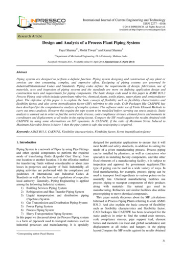
INTERNATIONAL JOURNAL OF CURRENT ENGINEERING AND SCIENTIFIC RESEARCH (IJCESR)B. Types of Landing gears based onarrangementTail wheel / conventional type landing gearTandem landing gearTricycle type landing gearFixed Landing gearsRetractable landing gearsC. Tricycle-Type Landing GearThe most commonly used landing geararrangement is the Tricycle-type arrangement. Itis comprised of two main gears behind the centreof gravity of the aircraft and one nose geararranged in a triangular fashion as in a tricycleand hence the name. The nose gear is used tosteer the aircraft using a hydraulic system. Themain gear on a tricycle-type landing geararrangement is attached to the wing structure orthe fuselage structure.The number and location of wheels on the maingear vary. Many main gears have two or morewheels. Multiple wheels spread the weight of theaircraft over a larger area and hence reduceloads. They also provide a safety margin shouldany of the tires fail. Heavy aircraft may use fouror more wheel assemblies on each main gear.Tri-cyclic landing gears have a series ofunquestioned advantages: Stability in braking; Steady touchdown with no risk of aerodynamicbounce; High pilot visibility during taxiing; Horizontal floor (occupants’ comfort and easyfreight loading); Low drag during take-off acceleration.As far as the strut design is concerned, twosolutions are mainly adopted: the telescopic andarticulated leg. The telescopic version is lighterbut requires higher ground clearance for lightaircraft. Therefore, we chose telescopic typewith tri-cyclic arrangement as it is the mostefficient for light weight aircraft we aredesigning. We can also classify the types asretractable and fixed Landing gears.A list of main requirements for an efficient andfunctional shock absorber follows: Damping characteristics should be different incompression and extension; the total orifice areacan be changed by inserting check valves insome orifices or valves that throttle the orificesin one flow direction; for high landing vertical velocities, the shockabsorber responds with high reaction forces dueto oil viscosity; to attenuate the load transfer tothe airplane structure, relief valves may beinstalled on the absorber, then flattening thereaction curve;In selecting the type, due recognition must , and relatively low cost of thesolid-spring shock absorbers. On smaller utilityaircraft, the weight penalty is usually negligibleand the noted advantages far outweigh thepenalties in such cases. There are two basic typesof shock absorbers: those using a solid springmade of steel or rubber and those using a fluidspring with gas or oil, or a mixture of those twothat is generally referred to as oleo-pneumatic.The gas is usually dry air or nitrogen. With theadvent of heavier airplanes, faster speeds andgreater wing loadings calls for the developmentof efficient shock absorbers. Shock absorbersevolved from a solid spring made of steel orrubber and those using a fluid spring with gas oroil, or a mixture of those two that is generallyreferred to as oleo-pneumatic.D. Solid Spring typeThese are majorly the steel coil springs and steelleaf spring type that are rarely used in presentday aircraft since they weigh seven times morethan the oleo-pneumatic type and are only about60 percent efficient.E. Oleo-Pneumatic typeMost of today's aircraft use oleo-pneumaticshock absorbers. They have the highestefficiencies of all shock absorber types and alsohave the best energy dissipation; i.e., unlike acoil spring that stores energy and then suddenlyreleases it, the oilis returned to its uncompressedstate at a controlled rate. An oleo-pneumaticstrut is an air–oil hydraulic shock absorber usedon the landing gear of most large aircraft andmany smaller ones. Oleo-pneumatic shockabsorber is considered the safest and the mostefficient modern shock absorption type withefficiencies up to 90%. This type of strut iscurrently the most advanced type being used inthe aviation industry. This is most apt for ourapplication and its design and working. Figure1.1 compares the efficiencies and relativeweights of the various shock absorber types.ISSN (PRINT): 2393-8374, (ONLINE): 2394-0697, VOLUME-5, ISSUE-2, 201846
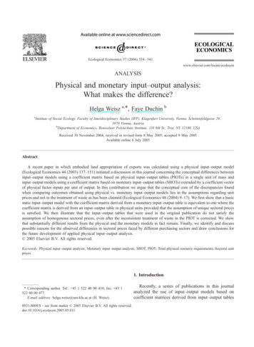
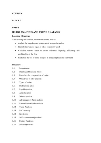
INTERNATIONAL JOURNAL OF CURRENT ENGINEERING AND SCIENTIFIC RESEARCH (IJCESR)(v) Filling must be by some automatic levellingscheme such as a stack pipe and not bymeasurement of the amount of oil.Fig 1.1: Shock absorber efficiencyA. Working of the strutThis shock absorber is adapted to be placedbetween the sprung mass and the unsprung massof a vehicle more particularly, between thelanding gear and aircraft structure. In addition, italso acts as an undercarriage which supports theweight of the aircraft on the ground. When theaircraft is stationary on the ground, its weight issupported by the oil and compressed gasin thecylinder. During landing, or when the aircrafttaxis over bumps, the piston slides up and down.Fig 1.2: Oleo-Pneumatic strutII. SHOCK ABSORBER STRUTA requirement of all aircraft shock absorbers isthat they absorb or dissipate the energy ofdescent or transient or vertical shocks withouttransferring them to the vehicle or aircraftstructure. The general requirements of anoleo-pneumatic landing gear shock absorberstrut are:(i) Overall length must be as short as possible,owing to the space constraints given the fact thatmost airplanes used today are powered using jetshence much lesser ground clearance.(ii)During compression, oil must be forcedpositively through the orifice so that the energyabsorbed by the liquid in the upper chamber isdistributed evenly.(iii) During extension, oil must be forcedpositively by a piston through holes, giving whatis called positive recoil control.(iv) Suitable flap must be provided so that duringmotion in one direction oil can flow freely todamp motion in the other direction.Fig 1.3: working of the strutIt compresses the gas, which acts as a spring,and forces oil through the orifice, which acts as adamper. The oleo-pneumatic shock absorberincorporates a pneumatic (gas) pressure chamber,a high gas pressure chamber and a hydraulicfluid (oil) pressure chamber. The oil chambercontains an orifice and metering pin; theycontrol the rate of collapse of the low pressuregas chamber. Metering pins are designed so as totake a nearly constant load throughout the strokeof the shock absorber, even under transientloading conditions. Thereby to obtain maximumefficiency we need relatively small orifice at theISSN (PRINT): 2393-8374, (ONLINE): 2394-0697, VOLUME-5, ISSUE-2, 201847
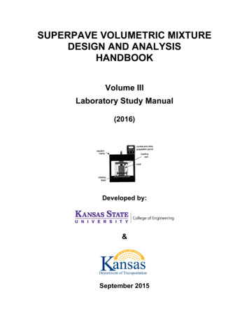
INTERNATIONAL JOURNAL OF CURRENT ENGINEERING AND SCIENTIFIC RESEARCH (IJCESR)beginning of the stroke, when the piston velocityis relatively slow; and during the middle part ofthe travel, a larger orifice is desirable and at theend of the travel a larger orifice is desirable.Figure shows the different positions of the strut.During the landing of the aircraft, the load orforce is applied to the lower end of the shockabsorber or to the lug causing the piston totelescope into cylinder, as illustrated. As thepiston moves upwardly into the chamber, itcauses an increase in the oil pressure in the oilchamber. Fluid then flows from the highpressure chamber to the low pressure chamberthrough orifice in the piston. Now this oil beginsto fill up the lower cylinder pushing the FloatingPiston and thereby compressing the gas. Duringextension the high pressure air pushes theFloating Piston upwards and the fluid goes backto the upper cylinder via the orifice.The figure below shows the position of theseparating piston, sliding piston and the cylinderposition during the condition of maximum loadthat is during landing, and extended conditionwhen the flight is airborne or when the tiresceases to be in contact with the ground and staticcondition when the flight is stationary.The inputs for the landing gear systemcalculations are the dimensions given in thefigure and other parameters such as aircraftweight, sink speed, load factor etc. The aircraft issteered by the nose landing gear during taxiingand during take-off. But the loads acting arecalculated with respect to the centre of gravity.Fig 1.4: Specifications for the Mini aircraftIII. CALCULATIONS FOR STATIC FORCETable 1: Mass acting on the MLGPOSITION OF STATIC FORCE WEIGHTCGAPPLIEDFWD CG40834 N2084 KgAFT CG44917 N2292 KgAfter calculating the forces, need to find outthe stroke, diameters of upper and lowercylinder.IV. CALCULATION OF STROKE RATIOSStroke ratios are based upon the differentpositions of the landing gear.V. CALCULATION OFVALUESPRESSURE AND VOLUMETable 2: Consolidated pressure values at variouspositionsMLGISOTHERMA VOLUMES.NOL PRESSUREPOSITION1Extended10.76 bar190*104mm32Static25 bar81.85*104mm33Compressed 74.24 bar28.15*104mm3VI. CALCULATION OF FORCES AND DESIGN OFORIFICETable 3: Consolidated Force and metering pinvaluesFORCE AT DIAMETERMLGS.NOPOSITIONISOTHERMAOFTHEL 2.653Compressed , by finding out the diameters of theorifice at various positions we will be able toarrive at the design of a metering pin and asubsequent metering pin that will facilitate theworking of the same. ANALYSIS USINGMATLAB and also preferred Load vsdisplacement characteristics for the strut.ISSN (PRINT): 2393-8374, (ONLINE): 2394-0697, VOLUME-5, ISSUE-2, 201848
INTERNATIONAL JOURNAL OF CURRENT ENGINEERING AND SCIENTIFIC RESEARCH (IJCESR)VII. PART MODELLINGA. Creo ParametricCreo Parametric 2.0 is the software that wasused in modelling the individual components inthe shock absorber strut assembly. Uppercylinder; Lower cylinder; Top cap; Floatingpiston.VIII. ASSIGNING OF MATERIAL PROPERTIESThe material properties are an importantparameter which is one of the main inputs for theanalysis.Assigning material properties is considered to beof prime importance for the sake of analysis. Theanalysis of the designed model in the followingmanner by using FEM and MATLAB.S L.COMPONENT owerCylinderMeteringPin luminium(7175 – 0852.7Table 4 : Material Properties of ComponentsIX. FINITE ELEMENT ANALYSISThe finite element method (FEM) is a numericaltechnique for finding approximate solutions toboundary value problems for partial differentialequations. It uses subdivision of a wholeproblem domain into simpler parts, called finiteelements, and variation methods from thecalculus of variations to solv
Fig 1.3: working of the strut It compresses the gas, which acts as a spring, and forces oil through the orifice, which acts as a damper. The oleo-pneumatic shock absorber incorporates a pneumatic (gas) pressure chamber, a high gas pressure chamber and a hydraulic fluid (oil) pressure chamber. The oil chamber contains an orifice and metering pin; they control the rate of collapse of the low .