Transcription
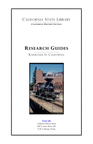
PUMP VisionTMTMPump Controls for Water and WastewaterPUMP Vision PV600TMUNIVERSAL PUMP CONTROLLER,RTU, and DATA LOGGER
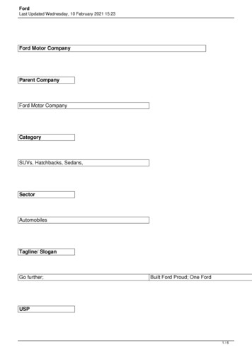
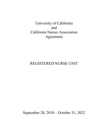
PUMP VisionTMTMPUMP Vision PV600UNIVERSAL PUMP CONTROLLER & RTUFor many years California Motor Controls has been producing touch screen pump controllers for the three largestwater/wastewater pump applications - Level control, Pressure Booster control, and Well Pump control. In the past,these controllers have always been separate products, making continuous software development costly.With our new PV600 Universal Pump Controller, we have combined these three applications into one easy to use, costeffective controller without compromising features or functions. All three operating modes (Level, Pressure, or Well)share much of the same program and offer full pump station management including PUMP Vision pump control,MOTOR Vision motor monitoring, SCADA Vision communication capability, and data logging.MAIN DASHBOARDWhen the PV600 is initialized, the system type is user selected and the controller configures itself for the application. A“Main Dashboard”, specific for either Level, Pressure, or Well pump control, provides complete system status on one easyto operate screen.COMMON TO ALL MODESDISPLAYS STATUS OF: ALL PROCESS PARAMETERS STATUS OF EACH PUMP ALARM CONDITIONS CLOCK BATTERY STATUSPROVIDES ACCESS TO: PUMP DASHBOARDS ALARM LOG TREND GRAPHS SYSTEM SET POINTS SYSTEM CONFIGURATION HELP SCREENSPRESSURE BOOSTERWELL PUMPWELL MODE INCLUDES: SYSTEM PRESSURE FILTER DP (user option) WATER LEVEL (user option) FLOW (user option)PRESSURE MODE INCLUDES: SYSTEM PRESSURE SYSTEM SET POINT SUCTION PRESSURE (user option) FLOW (user option) WATER TEMP (user option)TANK/SUMP LEVELLEVEL MODE INCLUDES: GRAPHIC AND DIGITAL LEVEL NUMBER OF PUMPS CALLED NUMBER OF PUMPS RUNNING STATUS OF EACH SET POINT FLOW (metered or calculated)PUMP DASHBOARDThe PV600 is user configured to operate simplex, duplex, triplex, and quadplex systems with numerous sequencingpossibilities. A “Pump Dashboard” is provided for each pump in the system that gives full control of the pumps. The PV600can operate FVNR, RVSS, or VFD starters, and since the Pump Dashboard provides such complete control of the VFD there isno need for a separate door mounted VFD keypad.ALL SYSTEMS: “Soft” HOA SELETOR SWITCH (user or RTU operated) STATUS INDICATION RUN DURATION NUMBER OF STARTS TOTAL HOURS (ETM) ACCESS TO RUN LOGVFD SYSTEMS: MANUAL SPEED CONTROL (with direct or ramped input) k(m)Wh DISPLAY MOTOR CURRENT (running amps) VFD SPEED COMMAND AND FEEDBACK ACCESS TO VFD FAULT LOGNON VFD SYSTEMVFD SYSTEM
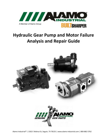
CONFIGURATIONMAIN CONFIGURATION MENUSetting the PV600 up to your uniqueapplication is simple due to the easyand intuitive menu structure that isaccessed through a three tier securitysystem. All parameters, such as type ofstarters or VFD, sensor types and ranges,set points, sequencing, communicationsand more, are easy to find and modifywithout referring to a manual.ALARM CONFIGURATIONRESTOREDIAGNOSTIC SCREENSThere are many diagnostic screens,such as this TEST MODE for theLevel Controller, and screens for I/Oand communication monitoring.HELP SCREENSBACKUPA setup screen is provided foreach alarm channel that allowsfor user configuration of thealarm’s actions and set pointsmaking it simple for the user toset the system up for theirspecific needs.Once your application is set, all parametersare backed up to Flash RAM in thecontroller and with the SD Card optioninstalled, the backup can be used to restorethe controller or another controller to theexact same setup, making replacementextremely easy.A HELP button is available onmost screens that links to built inhelp guides.DATA COLLECTIONThe PV600 records operating conditions with data logsand trend charts that are viewable on the controllerscreen and are stored on an SD card for permanentrecord. Separate logs exist for system faults, pumpfaults, and pump run times. Trend charts are providedfor level, pressure, flow, VFD speed, number of pumpsrunning, and temperature.With the SD Card option installed, the PV1200 can storeover five years of data at one second intervals. Thisdata can be displayed on the controller or exported tobe evaluated on a PC.The PV1200 can log flow rates and totals to providedaily, weekly, and monthly flow total reports. And inthe Level Control mode, the PV1200 can providecalculated flow rates without a flow meter installed.NOTE: THE LOOK AND ACCESS OF ALL SCREENS ARE ADJUSTED TO THE NEEDS THE APPLICATION.
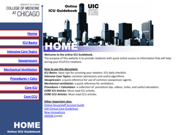
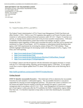
PUMP VisionTMTMPUMP Vision PV600LEVEL CONTROLLER MODEThe PV600 is more than just a level controller. Not only does itoperate just about any lift station application known, with MOTORVision it can closely monitor power conditions of the motors andpreempt failures by alerting maintenance personnel of impendingproblems. And because of the built in communication and emailcapabilities, and the ability to monitor pump station peripheralssuch as intrusion, generator status, and more, the PV600 fills the taskof pump station RTU. Add the extensive data logging capabilitiesand the PV1200 is a complete Pump Station Manager.LEVEL CONTROLLERIn addition to the Main Dashboard, Pump Dashboards, and configurationscreens, a set point overview page provides the status of the level controlsat a glance, and gives easy password protected access to level set point,timer, and alternator modifications.INPUTSThe PV600 can be configured to workwith almost any level sensor, including4-20 mA submersible transducers,ultrasonic, radar, standard float switches,and even ten segment probes. Forredundancy, a total of two transducersand two backup float switches can beconnected.PUMP STATION RTUThe PV600 not only sounds a local alarm upon afault condition, it can email or text message analert. The following alarms can be monitored:ALARMSSCADAHIGH LEVEL - (transducer)LOW LEVEL - (transducer)TRANSDUCER FAILURE/FLOAT FAILHIGH LEVEL FLOATLOW LEVEL FLOATPUMP FAILURE (each pump)MOTOR VISION FAULT (each pump)MOTOR TEMPERATURE (each pump)MOISTURE (each pump)VFD FAULT (each pump)PLUS 10 SYSTEM ALARM OPTIONSVisionTMSET POINT OVERVIEWACCESS TO ALL SETTINGS AND CONFIGURATIONVFD CONTROLSump pumps are typically “across-the-line” or full voltage starters, thoughsometimes VFDs are needed. The PV600 can operate the VFDs in either PID orProportional modes. In PID mode, the VFDs can pace either level or flow (or acombination of both).MOTOR VisionWhen the MOTOR Vision option is connected to the PV600,the pump motor is very closely monitored for signs oftrouble, especially important for submersible pumps.MOTOR VisionTMTM
PUMP VisionTMTMPUMP Vision PV600PRESSURE BOOSTER MODEThe Pressure Booster controller is designed to provide a constantpressure with variable flow conditions. By incorporating all of thelatest energy saving technologies such as variable speed drives,sensorless no flow shutdown, and seamless sequencing of multiple pumps, the PV600 provides a solid performance underextreme swings in operating conditions.PRESSURE BOOSTER CONTROLLERThe PV600 is simple to navigate, setup, and can be configured to operate all of the more than 1,000 booster control sytems that we havebuilt in the past 10 years. Every system is a little different in its control requirements and we have put every feature and function that wehave ever used into one controller that is easily setup to your needs.The PV600 can stage pumps on and off when the pressure drops, the flowincreases, the VFD(s) speed reaches a preset speed, or combinations of thesesensor inputs by simply selecting the choice for each stage. Slave and standbymode options, along with the alternation sequencer, make virtually any stagingneed possible.MAIN SEQUENCE SET UPSET POINT OVERVIEWACCESS TO ALL SETTINGS AND CONFIGURATIONPUMP STATION RTUFault conditions monitored in the PressureBooster Mode:SCADA VisionEach pump in the system can be individually set to stageon and off based on various combinations of conditions.TMALARMS:HIGH DISCHARGE PRESSURELOW DISCHARGE PRESSURETRANSDUCER FAILUREPUMP FAILUREHIGH SUCTION PRESSURELOW SUCTION PRESSUREVFD FAULTHIGH WATER TEMPERATUREMOTOR VISIONPLUS 10 SYSTEM ALARM OPTIONSSYSTEM START BASED ON (all user configured): BMS SIGNAL HARDWIRED ENABLE SWITCH PRESSURESYSTEM STOP BASED ON: MINIMUM RUN TIME MAX RUN TIME FLOW SWITCH SENSORLESS NO-FLOW SHUTDOWN PRESSURE BMS SIGNAL ALARM SHUTDOWNSPUMP STAGING (LAG PUMPS) BASED ON: PRESSURE VFD SPEED FLOW GPM MINIMUM AND MAXIMUM RUN TIMESNOTE: THE LOOK AND ACCESS OF ALL SCREENS WILL BE ADJUSTED TO THE NEEDS OF THE APPLICATION.
PUMP VisionTMTMPUMP Vision PV600WELL PUMP MODEThe PV600 brings all of the operation and protection capabilities typicallyreserved for municipal pump stations to the agricultural and domestic wellmarket that has historically had “bare bones” controls at remote installationsand no communication to the outside world.We now a cost effective monitoring and control solution available for wellpumps too!WELL PUMP CONTROLThe Well Pump mode operates a single pump and provides complete station management with the abilityto monitor and control all of the motor functions, filter status, and provide system alarm and RTU functionsfor the agricultural and domestic well market.MAIN DASHBOARDFault conditions monitored in theWell Pump Mode:ALARMSHIGH DISCHARGE PRESSURELOW DISCHARGE PRESSURETRANSDUCER FAILUREPUMP FAILUREDIRTY FILTER STAGE 1DIRTY FILTER STAGE 2HIGH TANK LEVELLOW TANK LEVELVFD FAULTLOW WATER LEVELPLUS 10 SYSTEM ALARM OPTIONSSET POINT OVERVIEWACCESS TO ALL SETTINGS AND CONFIGURATIONNOTE: THE LOOK AND ACCESS OF ALL SCREENS WILL BE ADJUSTED TO THE NEEDS OF THE APPLICATION.TIMER FUNCTIONSThe PV600 includes a number of timer functions thatwhen enabled by the user, provide importantfeatures that can further reduce maintenance andoperator oversight. These include:WELL PUMP Start Delay - “stagger start” the pumps Pump Down - periodic cleaning of the sump Exercise - periodic seize prevention Maximum Run - prevent excessive run time Flush - clear discharge at end of VFD run cycle Time Clock - run only during defined periods Purge Timer - for bubbler level sensing Maintenance - monitors pump run hours
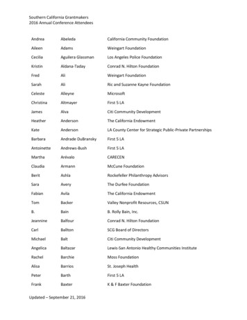
MOTOR VisionMOTOR VisionPOWER MONITOR“SMART” MOTOR STARTERS NETWORK CONNECTED TOPUMP Vision TO MONITOR PUMP OPERATING CONDITIONS.TMTMTHE DATA:(depending on the starter)MOTOR Vision starters can be across-the-line, VFD,or RVSS. They connect to PUMP Vision with aModbus network and provide important motoroperation data that is displayed on the screen andalso fed to the RTU for remote monitoring.AMPSVOLTSFREQUENCYPOWER FACTORGROUND FAULTKILOWATTSALARMS:(depending on the starter)RVSSFVNRU-LINEFVNRINSIGHTVFDTHERMAL OVERLOADSHORT-CIRCUITGROUND FAULTLOW OR HIGH VOLTAGELOW CURRENTMECHANICAL JAMLONG STARTPHASE FAILUREREVERSE PHASECONTACTOR FAILUREALARM STATUSPUMP STATION RTUSCADA VisionTMCOMMUNICATION SYSTEMS CONNECTED TO PUMP VisionTO REMOTELY MONITOR SYSTEM OPERATING CONDITIONS.The PV600 pump controller is also a Remote Terminal Unit (RTU) whichmeans that it can be connected by private network connection through wire,radio, WiFi, or cellular to a remote monitoring and control site or SCADAsystem. The RTU can also be connected to the Internet through a firewallallowing authorized access from anywhere.The PV600 comes with a serial port that is user configurable for station number, baud rate, and partity, with Modbus RTUprotocol. An optional Ethernet port provides Modbus IP protocol and possible Internet connection.Additional protocols such as Ethernet IP, Metasys N2, BACnet, Lon, and many others are available with our optionalprotocol converter.A free app allows users tosecurely log into the PUMP Visionproducts with a PC to monitorand control the station.Ask about our “SCADA Vision” SCADAsoftware. A ready to go SCADApackage optimized for use withPUMP Vision.When the PV600 is connected tothe Internet, it can send emailand text message alarm alerts.The PV600 has 10 System Alarms thatare monitored for the RTU, inaddition to the alarms specific toeach mode.5 are pre-labeled for common alarmsand five are “open channels” thatareavailable for customer definition.CONTROL POWER FAILUREUPS FAILUREGENERATOR FAULTINTRUSION ALARMHIGH DRYWELL LEVEL(5) USER DEFINED(These alarms require optional input expansion)
PUMP Vision PV600TMPower SupplyInput voltagePermissible rangeMax. current consumptionDigital Inputs *Number of inputsInput type24 VDC20.4 VDC to 28.8VDC with690 ma (with max. I/O)Galvanically isolated1824VDCTechnical SpecificationsSystem ConfigurationPassword protectedNumber of pumpsCascade control 8 pumpsType of starterModbus connected VFDsSequence3 level password (user selectable)One, two, three or fourLink two controllers for a Dual-quadplexFVNR, VFD, or RVSSAllen-Bradley, ABB, Schneider, Danfoss, Trane,TECO Westinghouse, others.Full alt., Jockey, Dual-duplex, standby, slavePump 1-4 HOA in AutoFunctionPump 1-4 run feedbackFlow meter high speed pulse input*Without expansionMode dependant alarm inputsDigital Outputs *Output type17Function*Without expansionAnalog Inputs *Input typeFunctionAnalog Outputs *Output typeFunction*Without expansionRelay, 3ARun outputs Pump 1, 2, 3, 4Fail outputs Pump 1, 2, 3, 4Mode dependant alarm outputsGeneral fault ind, contact, hornFour(1) PT100, (3) 4-20mALevel, Backup Level, Flow, Discharge Pressure,Suction Pressure, Temperature, Well Level, TankLevelLevel Controller ModeOperating directionLevel transducer, Back trVFD modesPressure Booster ModeSequencingSuction sensingSensorless no-flow shutdownVFD Speed, and/or flow, and/or pressurePressure/level transducer or switchYesAlarm ConfigurationEach of the alarm conditions can be ALL SYSTEMSset to:Pump failureEnable/disableVFD faultManual or auto resetStop pump(s)Sound hornMOTOR Vision faultTransducer failureLEVEL SYSTEMS4-20 maFlash the general fault lightLow level - transducerTrigger fault contactHigh level - float switchSend e-mailTime delayLow level - float switchSeal failureHigh motor temperaturePump 1, 2, 3, 4, VFD speed reference (Only fornon-network VFDs)Pressure, Flow, LevelOptional FunctionsGenerator & Power monitoring, Remote set pointadjust, Intrusion, float switch level sensing, UPSfail, and more.24VDC, Relay, 4-20 ma, 4-20 maOptional alarmsIntrusionHigh level - transducerBOOSTER SYSTEMSHigh system pressureLow system pressureGenerator faultHigh suction pressure/levelPower failureUPS failureLow suction pressure/levelHigh water temperatureMoreEnvironmentOperational temperatureRelative humidityEnvironmental ratingProportion, PID Level, PID Flow, combinationIlluminate general fault light16 DI, 8 DO, 4 AI, 2 AOScreen SaverZero and scale are user settableFourOption I/OOutput typeGraphic Display ScreenScreen typeIllumination backlightDisplay resolutionViewing areaColorsTouch indicationKeypadPump up, pump downWELL SYSTEMSHigh system pressureTFT, touch resistive analogLow system pressureWhite LED, software-controlledDirty filter stage 1320 X 240 pixels6" diagonal (nom.)Dirty filter stage 2High motor temperature256Via buzzerData LoggingDisplays virtual keyboard when theapplication requires data entry.1-99 min adjustable time delayGENERAL FAULT LOGVFD FAULT LOGS0 to 50 C (32 to 122 F)10% to 95% (non-condensing)IP65/NEMA4X1000 faults, FIFO memoryAll system faults are loggedController screen, memory, SD card250 faults, FIFO memoryOne log for each VFD, records all faultsController screen, memory, SD cardPUMP RUN LOG500 events, FIFO memoryRecords start time, stop time, run durationController screen, memory, SD cardDimensionsSizeWeightMiscellaneousBattery back-up7.75" x 5.77" x 3.5"2 lb. 4 oz. (1029 grams)7 years typical at 25 C, battery back-up for RTCand system data, incl. variable dataFLOW LOGSTrend GraphBattery back-upBattery replacementYes. Coin-type 3V, lithium battery, CR2450With optional SD cardCommunication PortsPort 1, Port 2Port 3 (optional)2 channel, RS232/RS485EthernetEvent logStore event informationto SD CardRemovable MemorySD cardSD Card back-up/RestoreCMOptional - Up to 16GBStore event log, trend data ( 5 yrs)All system configuration parameters are saved toSD Card for future restore.E-mailSend alarm notificationE-mail or text message100 periods each, FIFO memorySeparate daily, weekly, monthly flow totalsController screen, memory, SD card7 years typical at 25 C, battery back-up for RTCand system data, incl. variable data63 months of data stored every secondAll event and fault logs record to SD card.Depending on the size of the SD, many years ofdata can be stored.Send to SMTP server6 recipient numbersEthernet port option requiredaliforniaCalifornia Motor Controls, Inc. - 3070 Bay Vista Ct. - Suite C - Benicia, CA 94510 - (707) 746-6255 - www.cmcontrols.com
Sump pumps are typically “across-the-line” or full voltage starters, though sometimes VFDs are needed. The PV600 can operate the VFDs in either PID or Proportional modes. In PID mode, the VFDs