Transcription
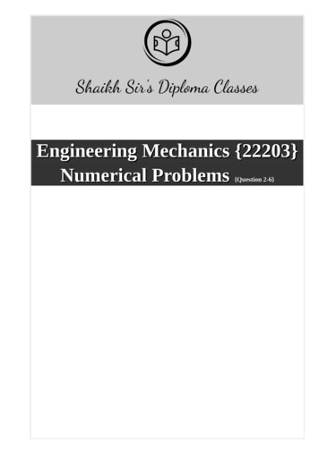
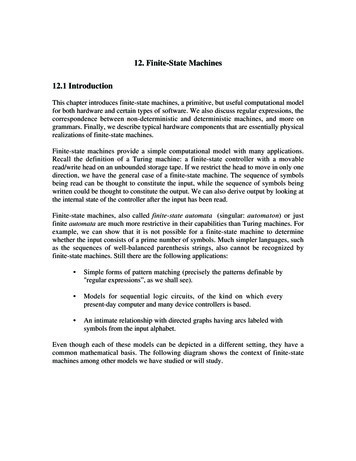
12. Finite-State Machines12.1 IntroductionThis chapter introduces finite-state machines, a primitive, but useful computational modelfor both hardware and certain types of software. We also discuss regular expressions, thecorrespondence between non-deterministic and deterministic machines, and more ongrammars. Finally, we describe typical hardware components that are essentially physicalrealizations of finite-state machines.Finite-state machines provide a simple computational model with many applications.Recall the definition of a Turing machine: a finite-state controller with a movableread/write head on an unbounded storage tape. If we restrict the head to move in only onedirection, we have the general case of a finite-state machine. The sequence of symbolsbeing read can be thought to constitute the input, while the sequence of symbols beingwritten could be thought to constitute the output. We can also derive output by looking atthe internal state of the controller after the input has been read.Finite-state machines, also called finite-state automata (singular: automaton) or justfinite automata are much more restrictive in their capabilities than Turing machines. Forexample, we can show that it is not possible for a finite-state machine to determinewhether the input consists of a prime number of symbols. Much simpler languages, suchas the sequences of well-balanced parenthesis strings, also cannot be recognized byfinite-state machines. Still there are the following applications: Simple forms of pattern matching (precisely the patterns definable by"regular expressions”, as we shall see). Models for sequential logic circuits, of the kind on which everypresent-day computer and many device controllers is based. An intimate relationship with directed graphs having arcs labeled withsymbols from the input alphabet.Even though each of these models can be depicted in a different setting, they have acommon mathematical basis. The following diagram shows the context of finite-statemachines among other models we have studied or will study.
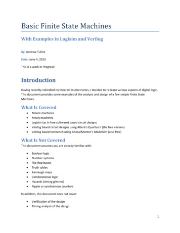
472Finite-State MachinesTuring MachinesContext-Free GrammarsSequentialLogic SwitchingCircuitsFinite-State Machines,Finite-State AutomataFinite-State GrammarsCombinationalLogic SwitchingCircuitsFinite DirectedLabelled GraphsRegular Expressions,Regular LanguagesFigure 189: The interrelationship of various modelswith respect to computational or representational power.The arrows move in the direction of restricting power.The bi-directional arrows show equivalences.Finite-State Machines as Restricted Turing MachinesOne way to view the finite-state machine model as a more restrictive Turing machine isto separate the input and output halves of the tapes, as shown below. However,mathematically we don't need to rely on the tape metaphor; just viewing the input andoutput as sequences of events occurring in time would be adequate.Output written so farInput to be readqDirection of head motionFigure 190: Finite-state machine as a one-way moving Turing machineInput to be readqDirection of head motionOutput written so farFigure 191: Finite-state machine as viewed with separate input and output
Finite-State Machines473Direction of tape motionqreadingwritingDirection of tape motionFigure 192: Finite-state machine viewed as a stationary-head, moving-tape, deviceSince the motion of the head over the tape is strictly one-way, we can abstract away theidea of a tape and just refer to the input sequence read and the output sequence produced,as suggested in the next diagram. A machine of this form is called a transducer, since itmaps input sequences to output sequences. The term Mealy machine, after George H.Mealy (1965), is also often used for transducer.Output sequencey y yInput sequencex x x x .y .1 2 3 41 2 3 4Finite set ofinternal statesFigure 193: A transducer finite-state machine viewed as a tapeless "black box"processing an input sequence to produce an output sequenceOn the other hand, occasionally we are not interested in the sequence of outputsproduced, but just an output associated with the current state of the machine. This simplermodel is called a classifier, or Moore machine, after E.F. Moore (1965).Outputassociatedwith currentstatezInput sequencex x x x .1 2 3 4Finite set ofinternal statesFigure 194: Classifier finite-state machine.Output is a function of current state, rather than being a sequence
474Finite-State MachinesModeling the Behavior of Finite-State MachinesConcentrating initially on transducers, there are several different notations we can use tocapture the behavior of finite-state machines: As a functional program mapping one list into another. As a restricted imperative program, reading input a single character at a timeand producing output a single character at a time. As a feedback system. Representation of functions as a table Representation of functions by a directed labeled graphFor concreteness, we shall use the sequence-to-sequence model of the machine, althoughthe other models can be represented similarly. Let us give an example that we can use toshow the different notations:Example: An Edge-DetectorThe function of an edge detector is to detect transitions between two symbols in the inputsequence, say 0 and 1. It does this by outputting 0 as long as the most recent input symbolis the same as the previous one. However, when the most recent one differs from theprevious one, it outputs a 1. By convention, the edge detector always outputs 0 afterreading the very first symbol. Thus we have the following input output sequence pairs forthe edge-detector, among an infinite number of possible 1110101101010100etc.001011011101110
Finite-State Machines475Functional Program View of Finite-State MachinesIn this view, the behavior of a machine is as a function from lists to lists.Each state of the machine is identified with such a function.The initial state is identified with the overall function of the machine.The functions are interrelated by mutual recursion: when a function processes an inputsymbol, it calls another function to process the remaining input.Each function:looks at its input by one application of first,produces an output by one application of cons, the first argument of which isdetermined purely by the input obtained from first, andcalls another function (or itself) on rest of the input.We make the assumptions that:The result of cons, in particular the first argument, becomes partially available evenbefore its second argument is computed.Each function will return NIL if the input list is NIL, and we do not show thisexplicitly.Functional code example for the edge-detector:We will use three functions, f, g, and h. The function f is the overall representation of theedge detector.f([0 Rest]) [0 g(Rest)];f([1 Rest]) [0 h(Rest)];f([]) [];g([0 Rest]) [0 g(Rest)];g([1 Rest]) [1 h(Rest)];g([]) [];h([0 Rest]) [1 g(Rest)];h([1 Rest]) [0 h(Rest)];h([]) [];Notice that f is never called after its initial use. Its only purpose is to provide the properoutput (namely 0) for the first symbol in the input.
476Finite-State MachinesExample of f applied to a specific input:f([0, 1, 1, 1, 0]) [0, 1, 0, 0, 1]An alternative representation is to use a single function, say k, with an extra argument,treated as just a symbol. This argument represents the name of the function that wouldhave been called in the original representation. The top-level call to k will give the initialstate as this argument:k("f", [0 Rest]) [0 k("g", Rest)];k("f", [1 Rest]) [0 k("h", Rest)];k("f", []) [];k("g", [0 Rest]) [0 k("g", Rest)];k("g", [1 Rest]) [1 k("h", Rest)];k("g", []) [];k("h", [0 Rest]) [1 k("g", Rest)];k("h", [1 Rest]) [0 k("h", Rest)];k("h", []) [];The top level call with input sequence x is k("f", x) since "f" is the initial state.Imperative Program View of Finite-State MachinesIn this view, the input and output are viewed as streams of characters. The programrepeats the processing cycle:read character,select next state,write character,go to next statead infinitum. The states can be represented as separate "functions", as in the functionalview, or just as the value of one or more variables. However the allowable values must berestricted to a finite set. No stacks or other extendible structures can be used, and anyarithmetic must be restricted to a finite range.The following is a transliteration of the previous program to this view. The program isstarted by calling f(). Here we assume that read() is a method that returns the nextcharacter in the input stream and write(c) writes character c to the output stream.void f()// initial function{switch( read() ){case '0': write('0'); g(); break;case '1': write('0'); h(); break;}
Finite-State Machines477}void g()// previous input was 0{switch( read() ){case '0': write('0'); g(); break;case '1': write('1'); h(); break; // 0 - 1 transition}}void h()// previous input was 1{switch( read() ){case '0': write('1'); g(); break; // 1 - 0 transitioncase '1': write('0'); h(); break;}}[Note that this is a case where all calls can be "tail recursive", i.e. could be implementedas gotos by a smart compiler.]The same task could be accomplished by eliminating the functions and using a singlevariable to record the current state, as shown in the following program. As before, weassume read() returns the next character in the input stream and write(c) writescharacter c to the output stream.static final char f 'f';static final char g 'g';static final char h 'h';static final char initial state f;main(){char current state, next state;char c;current state initial state;// set of states
478Finite-State Machineswhile( (c read()) ! EOF ){switch( current state ){case f:// initial stateswitch( c ){case '0': write('0'); next state g; break;case '1': write('0'); next state h; break;}break;case g:// last input was 0switch( c ){case '0': write('0'); next state g; break;case '1': write('1'); next state h; break; // 0 - 1}break;case h:switch( c{case '0':case '1':}break;}current state}// last input was 1)write('1'); next state g; break; // 1 - 0write('0'); next state h; break; next state;}Feedback System View of Finite-State MachinesThe feedback system view abstracts the functionality of a machine into two functions, thenext-state or state-transition function F, and the output function G.F: States x Symbols Statesstate-transition functionG: States x Symbols Symbolsoutput functionThe meaning of these functions is as follows:F(q, σ) is the state to which the machine goes when currently in state q and σ is readG(q, σ) is the output produced when the machine is currently in state q and σ is readThe relationship of these functions is expressible by the following diagram.
Finite-State Machines479output functionoutputGnext-state functionFinput delay or memoryThe currentstateFigure 195: Feedback diagram of finite-state machine structureFrom F and G, we can form two useful functionsF*: States x Symbols* Statesextended state-transition functionG*: States x Symbols* Symbolsextended output functionwhere Symbols* denotes the set of all sequences of symbols. This is done by induction:F*(q, λ) qF*(q, xσ) F(F*(q, x), σ )G*(q, λ) λG*(q, xσ) G*(q, x) G(F*(q, x), σ )In the last equation, juxtaposition is like cons’ing on the right. In other words, F*(q, x) isthe state of the machine after all symbols in the sequence x have been processed, whereasG*(q, x) is the sequence of outputs produced along the way. In essence, G* can beregarded as the function computed by a transducer. These definitions could be transcribedinto rex rules by representing the sequence xσ as a list [σ x] with λ corresponding to [ ].Tabular Description of Finite-State MachinesThis description is similar to the one used for Turing machines, except that the motion isleft unspecified, since it is implicitly one direction. In lieu of the two functions F and G, a
480Finite-State Machinesfinite-state machine could be specified by a single function combining F and G of theform:States x Symbols States x Symbolsanalogous to the case of a Turing machine, where we included the motion:States x Symbols Symbols x Motions x StatesThese functions can also be represented succinctly by a table of 4-tuples, similar to whatwe used for a Turing machine, and again called a state transition table:State1, Symbol1, State2, Symbol2Such a 4-tuple means the following:If the machine's control is in State1 and reads Symbol1, then machine willwrite Symbol2 and the next state of the controller will be State2.The state-transition table for the edge-detector machine is:start statecurrent stateffgghhinput symbol010101next stateghghghoutput symbol000110Unlike the case of Turing machines, there is no particular halting convention. Instead,the machine is always read to proceed from whatever current state it is in. This does notstop us from assigning our own particular meaning of a symbol to designate, for example,end-of-input.Classifiers, Acceptors, Transducers, and SequencersIn some problems we don't care about generating an entire sequence of output symbols asdo the transducers discussed previously. Instead, we are only interested in categorizingeach input sequence into one of a finite set of possibilities. Often these possibilities canbe made to derive from the current state. So we attach the result of the computation to thestate, rather than generate a sequence. In this model, we have an output functionc: Q C
Finite-State Machines481which gives a category or class for each state. We call this type of machine a classifier orcontroller. We will study the conrtoller aspect further in the next chapter. For now, wefocus on the classification aspect. In the simplest non-trivial case of classifier, there aretwo categories. The states are divided up into the "accepting" states (class 1, say) and the"rejecting" states (class 0). The machine in this case is called an acceptor or recognizer.The sequences it accepts are those given byc(F*(q0, x)) 1that is, the sequences x such that, when started in state q0, after reading x, the machine isin a state q such that c(q) 1. The set of all such x, since it is a set of strings, is alanguage in the sense already discussed. If A designates a finite-state acceptor, thenL(A) { x in Σ* c(F*(q0, x)) 1}is the language accepted by A.The structure of a classifier is simpler than that of a transducer, since the output is only afunction of the state and not of both the state and input. The structure is shown asfollows:outputoutput functionGnext-state functionFinput delay or memoryThe currentstateFigure 196: Feedback diagram of classifier finite-state machine structureA final class of machine, called a sequencer or generator, is a special case of atransducer or classifier that has a single-letter input alphabet. Since the input symbols areunchanging, this machine generates a fixed sequence, interpreted as either the outputsequence of a transducer or the sequence of classifier outputs. An example of a sequenceris a MIDI (Musical Instrument Digital Interface) sequencer, used to drive electronicmusical instruments. The output alphabet of a MIDI sequencer is a set of 16-bit words,each having a special interpretation as pitch, note start and stop, amplitude, etc. Although
482Finite-State Machinesmost MIDI sequencers are programmable, the program typically is of the nature of aninitial setup rather than a sequential input.Description of Finite-State Machines using GraphsAny finite-state machine can be shown as a graph with a finite set of nodes. The nodescorrespond to the states. There is no other memory implied other than the state shown.The start state is designated with an arrow directed into the corresponding node, butotherwise unconnected.Figure 197: An unconnected in-going arc indicates that the node is the start stateThe arcs and nodes are labeled differently, depending on whether we are representing atransducer, a classifier, or an acceptor. In the case of a transducer, the arcs are labeledσ/δ as shown below, where σ is the input symbol and δ is the output symbol. The statetransition is designated by virtue of the arrow going from one node to another.qσ/δ1q2Figure 198: Transducer transition from q1 to q2, based on input σ, giving output δIn the case of a classifier, the arrow is labeled only with the input symbol. The categoriesare attached to the names of the states after /.q /c1σ1q2 / c2Figure 199: Classifier transition from q1 to q2, based on input σIn the case of a acceptor, instead of labeling the states with categories 0 and 1, wesometimes use a double-lined node for an accepting state and a single-lined node for arejecting state.
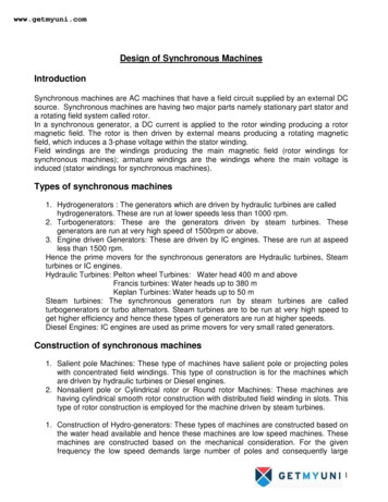
Finite-State Machines483qaFigure 200: Acceptor, an accepting stateTransducer ExampleThe edge detector is an example of a transducer. Here is its graph:0/0f1/0g0/00/11/1h1/0Figure 201: Directed labeled graph for the edge detectorLet us also give examples of classifiers and acceptors, building on this example.Classifier ExampleSuppose we wish to categorize the input as to whether the input so far contains 0, 1, ormore than 1 "edges" (transitions from 0 to 1, or 1 to 0). The appropriate machine type isclassifier, with the outputs being in the set {0, 1, more}. The name "more" is chosenarbitrarily. We can sketch how this classifier works with the aid of a graph.The construction begins with the start state. We don't know how many states there will beinitially. Let us use a, b, c, . as the names of the states, with a as the start state. Eachstate is labeled with the corresponding class as we go. The idea is to achieve a finiteclosure after some number of states have been added. The result is shown below:
484Finite-State Machines101d/1b/000a/00, 1f / more10110e/1c/0Figure 202: Classifier for counting 0, 1, or more than 1 edgesAcceptor ExampleLet us give an acceptor that accepts those strings with exactly one edge. We can use thestate transitions from the previous classifier. We need only designate those states thatcategorize there being one edge as accepting states and the others as rejecting states.101db00a0, 1f10110ceFigure 203: Acceptor for strings with exactly one edge. Accepting states are d and e.
Finite-State Machines485Sequencer ExampleThe following sequencer, where the sequence is that of the outputs associated with eachstate, is that for a naive traffic light:q0 /greenq1 /yellowq2 /redFigure 204: A traffic light sequencerExercises1 Consider a program that scans an input sequence of characters to determinewhether the sequence as scanned so far represents either an integer numeral, afloating-point numeral, unknown, or neither. As it scans each character, it outputsthe corresponding assessment of the input. For example,Input Scanned1 1 rDescribe the scanner as a finite-state transducer using the various methodspresented in the text.2 Some organizations have automated their telephone system so that messages canbe sent via pushing the buttons on the telephone. The buttons are labeled withboth numerals and letters as shown:
486Finite-State Machines12abc3def4ghi5jkl6mno7prs8tuv9wxy*0#Notice that certain letters are omitted, presumably for historical reasons.However, it is common to use * to represent letter q and # to represent letter z.Common schemes do not use a one-to-one encoding of each letter. However, ifwe wanted such an encoding, one method would be to use two digits for eachletter:The first digit is the key containing the letter.The second digit is the index, 1, 2, or 3, of the letter on the key. Forexample, to send the word "cat", we'd punch:2 3c2 1a8 1tAn exception would be made for 'q' and 'z', as the only letters on the keys'*' and '#' respectively.Give the state-transition table for communicating a series of any of the twenty-sixletters, where the input alphabet is the set of digits {1, ., 9, *, #} and the outputalphabet is the set of available letters. Note that outputs occur only every otherinput. So we need a convention for what output will be shown in the transducer incase there is no output. Use λ for this output.3 The device sketched below is capable of partially sensing the direction(clockwise, counterclockwise, or stopped) of a rotating disk, having sectorspainted alternating gray and white. The two sensors, which are spaced so as to fitwell within a single sector, regularly transmit one of four input possibilities: wg(white-gray), ww (white-white), gw (gray-white), and gg (gray-gray). Thesampling rate must be fast enough, compared with the speed of the disk, thatartifact readings do not take place. In other words, there must be at least onesample taken every time the disk moves from one of the four input combinationsto another. From the transmitted input values, the device produces the directional
Finite-State Machines487information. For example, if the sensors received wg (as shown), then ww forawhile, then gw, it would be inferred that the disk is rotating clockwise. On theother hand, if it sensed gw more than once in a row, it would conclude that thedisk has stopped. If it can make no other definitive inference, the device willindicate its previous assessment. Describe the device as a finite-state transducer,using the various methods presented in the text.sensorsoutputFigure 205: A rotational direction detector4 Decide whether the wrist-watch described below is best represented as a classifieror a transducer, then present a state-transition diagram for it. The watch has achronograph feature and is controlled by three buttons, A, B, and C. It has threedisplay modes: the time of day, the chronograph time, and "split" time, a savedversion of the chronograph time. Assume that in the initial state, the watchdisplays time of day. If button C is pressed, it displays chronograph time. If C ispressed again, it returns to displaying time of day. When the watch is displayingchronograph time or split time, pressing A starts or stops the chronograph.Pressing B when the chronograph is running causes the chronograph time to berecorded as the split time and displayed. Pressing B again switches to displayingthe chronograph. Pressing B when the chronograph is stopped resets thechronograph time to 0.5 A certain vending machine vends soft drinks that cost 0.40. The machine acceptscoins in denominations of 0.05, 0.10, and 0.25. When sufficient coins havebeen deposited, the machine enables a drink to be selected and returns theappropriate change. Considering each coin deposit and the depression of the drinkbutton to be inputs, construct a state-transition diagram for the machine. Theoutputs will be signals to vend a drink and return coins in selected denominations.Assume that once the machine has received enough coins to vend a drink, but thevend button has still not been depressed, that any additional coins will just bereturned in kind. How will your machine handle cases such as the sequence ofcoins 10, 10, 10, 5, 25?
4886 Finite-State MachinesConsider the problem of controlling traffic at an intersection such as shownbelow.LegendTraffic flow directionPresence sensorThrough trafficTraffic lightCross trafficFigure 206: A traffic intersectionTime is divided into equal-length intervals, with sensors sampling the presence oftraffic just before the end of an interval. The following priority rules apply:1.If no traffic is present, through-traffic has the right-of-way.2.If through-traffic is still present at the end of the first interval duringwhich through-traffic has had the right-of-way, through-traffic is given theright-of-way one additional interval.3.If cross-traffic is present at the end of the second consecutive intervalduring which through-traffic has had the right-of-way, then cross-traffic isgiven the right-of-way for one interval.4.If cross-traffic is present but through-traffic is absent, cross-trafficmaintains the right-of-way until an interval in which through-trafficappears, then through-traffic is given the right-of-way.Describe the traffic controller as a classifier that indicates which traffic has theright-of-way.7 A bar code represents bits as alternating light and dark bands. The light bands areof uniform width, while the dark bands have width either equal to, or double, thewidth of the light bands. Below is an example of a code-word using the bar code.The tick marks on top show the single widths.
Finite-State Machines489Figure 207: A bar code schemeAssume that a bar-code reader translates the bands into symbols, L for light, D fordark, one symbol per single width. Thus the symbol sequence for the code-wordabove would beL D L D D L D D L D L D D L D LA bar pattern represents a binary sequence as follows: a 0 is encoded as LD,while a 1 is encoded as LDD. A finite-state transducer M can translate such acode into binary. The output alphabet for the transducer is {0, 1, , end}. Whenstarted in its initial state, the transducer will "idle" as long as it receives only L's.When it receives its first D, it knows that the code has started. The transducer willgive output 0 or 1 as soon it has determined the next bit from the bar pattern. Ifthe bit is not known yet, it will give output . Thus for the input sequence above,M will produce0 1 1 0 1 0L D L D D L D D L D L D D L D Lwhere we have repeated the input below the output for convenience. Thetransducer will output the symbol end when it subsequently encounters two L's ina row, at which point it will return to its initial state.a. Give the state diagram for transducer M, assuming that only sequences of theindicated form can occur as input.b. Certain input sequences should not occur, e.g. L D D D. Give a state-transitiondiagram for an acceptor A that accepts only the sequences corresponding to avalid bar code.8 A gasoline pump dispenses gas based on credit card and other input from thecustomer. The general sequence of events, for a single customer is:Customer swipes credit card through the slot.Customer enters PIN (personal identification number) on keypad, withappropriate provisions for canceling if an error is made.Customer selects grade of gasoline.
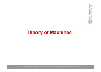
490Finite-State MachinesCustomer removes nozzle.Customer lifts pump lever.Customer squeezes or releases lever on nozzle any number of times.Customer depresses pump lever and replaces nozzle.Customer indicates whether or not a receipt is wanted.Sketch a state diagram for modeling such as system as a finite-state machine.Inter-convertibility of Transducers and Classifiers (Advanced)We can describe a mathematical relationship between classifiers and transducers, so thatmost of the theory developed for one will be applicable to the other. One possibleconnection is, given an input sequence x, record the outputs corresponding to the statesthrough which a classifier goes in processing x. Those outputs could be the outputs of anappropriately-defined transducer. However, classifiers are a little more general in thissense, since they give output even for the empty sequence λ, whereas the output for atransducer with input λ is always just λ . Let us work in terms of the followingequivalence:A transducer T started in state q0 is equivalent to a classifier C started in state q0if, for any non-empty sequence x, the sequence of outputs emitted by T is thesame as the sequence of outputs of the states through which C passes.With this definition in mind, the following would be a classifier equivalent to the edgedetector transducer presented earlier.0f/arb0g0/0111h0/0100g1/101h1/1Figure 208: A classifier formally equivalent to the edge-detector transducer
Finite-State Machines491To see how we constructed this classifier, observe that the output emitted by a transducerin going from a state q to a state q', given an input symbol σ, should be the same as theoutput attached to state q' in the classifier. However, we can't be sure that all transitionsinto a state q' of a transducer produce the same output. For example, there are twotransitions to state g in the edge-detector that produce 0 and one that produces 1, andsimilarly for state h. This makes it impossible to attach a fixed input to either g or h.Therefore we need to "split" the states g and h into two, a version with 0 output and aversion with 1 output. Call these resulting states g0, g1, h0, h1. Now we can construct anoutput-consistent classifier from the transducer. We don't need to split f, since it has avery transient character. Its output can be assigned arbitrarily without spoiling theequivalence of the two machines.The procedure for converting a classifier to a transducer is simpler. When the classifiergoes from state q to q', we assign to the output transition the state output value c(q'). Thefollowing diagram shows a transducer equivalent to the classifier that reports 0, 1, ormore re0/1eFigure 209: A transducer formally equivalent to the edge-counting classifierExercises1 Whichever model, transducer or classifier, you chose for the wrist-watch problemin the previous exercises, do a formal conversion to the other model.Give a state-transition graph or other equivalent representation for the followingmachines.2 MB2 (multipy-by-two) This machine is a transducer with binary inputs andoutputs, both least-significant bit first, producing a numeral that is twice theinput. That is, if the input is .x2x1x0 where x0 is input first, then the output willbe . x2x1x00 where 0 is output first, then x0, etc. For example:
492Finite-State Machinesinput001011010111010110101011first bit input output010110101100101101010110input decimal013114343output decimal02622incomplete86Notice tha
An intimate relationship with directed graphs having arcs labeled with symbols from the input alphabet. Even though each of these models can be depicted in a different setting, they have a common mathematical basis. The following diagram shows the context of finite-state machines among other models we have studied or will study.