Transcription
Theory of MachinesDr. Anwar Abu-Zarifa . Islamic University of Gaza . Department of Mechanical Engineering . 20121
Syllabus and Course OutlineFaculty of EngineeringDepartment of Mechanical EngineeringEMEC 3302, Theory of MachinesInstructor: Dr. Anwar Abu-ZarifaOffice:IT Building, Room: I413Tel: 2821eMail: aabuzarifa@iugaza.edu.psWebsite: http://site.iugaza.edu.ps/abuzarifaOffice Hrs: see my websiteSAT09:30 – 11:00Q412MON09:30 – 11:00Q412Dr. Anwar Abu-Zarifa . Islamic University of Gaza . Department of Mechanical Engineering . 20122
Text Book: R. L. Norton, Design of Machinery “An Introduction to theSynthesis and Analysis of Mechanisms and Machines”, McGraw HillHigher Education; 3rd editionReference Books: John J. Uicker, Gordon R. Pennock, Joseph E. Shigley, Theory of Machinesand Mechanisms R.S. Khurmi, J.K. Gupta,Theory of Machines Thomas Bevan, The Theory of Machines The Theory of Machines by Robert Ferrier McKay Engineering Drawing And Design, Jensen ect., McGraw-Hill Science, 7thEdition, 2007 Mechanical Design of Machine Elements and Machines, Collins ect., Wiley,2 Edition, 2009Dr. Anwar Abu-Zarifa . Islamic University of Gaza . Department of Mechanical Engineering . 20123
Grading:AttendanceDesign ProjectMidtermFinal exam5%25%30%40%Course Description:The course provides students with instruction in the fundamentals of theory ofmachines. The Theory of Machines and Mechanisms provides the foundationfor the study of displacements, velocities, accelerations, and static anddynamic forces required for the proper design of mechanical linkages, cams,and geared systems.Dr. Anwar Abu-Zarifa . Islamic University of Gaza . Department of Mechanical Engineering . 20124
Course Objectives:Students combine theory, graphical and analytical skills to understandthe Engineering Design. Upon successful completion of the course,the student will be able: To develop the ability to analyze and understand the dynamic(position, velocity, acceleration, force and torque) characteristics ofmechanisms such as linkages and cams.To develop the ability to systematically design and optimizemechanisms to perform a specified task.To increase the ability of students to effectively present written,oral, and graphical solutions to design problems.To increase the ability of students to work cooperatively on teamsin the development of mechanism designs.Dr. Anwar Abu-Zarifa . Islamic University of Gaza . Department of Mechanical Engineering . 20125
Chapter 1IntroductionDr. Anwar Abu-Zarifa . Islamic University of Gaza . Department of Mechanical Engineering . 20126
DefinitionsThe subject Theory of Machines may be defined as that branch ofEngineering-science, which deals with the study of relative motionbetween the various parts of a machine, and forces which act onthem. The knowledge of this subject is very essential for anengineer in designing the various parts of a machine.Kinematics: The study of motion without regard to forcesMore particularly, kinematics is the study of position, displacement,rotation, speed, velocity, and acceleration.Dr. Anwar Abu-Zarifa . Islamic University of Gaza . Department of Mechanical Engineering . 20127
Kinetics: The study of forces on systems in motionA mechanism: is a device that transforms motion to some desirable patternand typically develops very low forces and transmits little power.A machine: typically contains mechanisms that are designed to providesignificant forces and transmit significant power.Dr. Anwar Abu-Zarifa . Islamic University of Gaza . Department of Mechanical Engineering . 20128
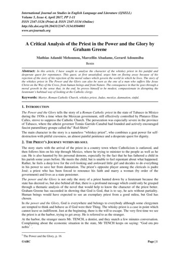
Application of KinematicsAny machine or device that moves contains one or more kinematic elementssuchAs linkages, gears . belts and chains.Bicycle is a simple example of a kinematic system that contains a chain driveto provide Torque.Dr. Anwar Abu-Zarifa . Islamic University of Gaza . Department of Mechanical Engineering . 20129
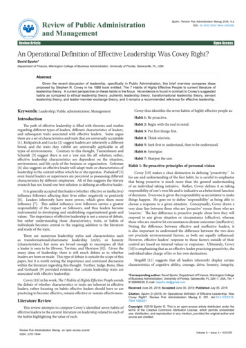
An Automobile contains many more examples of kin-systems the transmission is full of gears .Dr. Anwar Abu-Zarifa . Islamic University of Gaza . Department of Mechanical Engineering . 201210
Dr. Anwar Abu-Zarifa . Islamic University of Gaza . Department of Mechanical Engineering . 201211
Chapter 2DEGREES OF FREEDOM (MOBILITY)Dr. Anwar Abu-Zarifa . Islamic University of Gaza . Department of Mechanical Engineering . 201212
Degrees of Freedom (DOF) or Mobility DOF: Number of independent parameters(measurements) needed to uniquely defineposition of a system in space at any instant oftime. A mechanical system’s mobility (M) can beclassified according to the number of degreesof freedom (DOF). DOF is defined with respect to a selected frameof reference (ground).Dr. Anwar Abu-Zarifa . Islamic University of Gaza . Department of Mechanical Engineering . 201213
Rigid body in a plane has 3 DOF: x,y,z Rigid body in 3D-space has 6 DOF, 3 translations & 3rotations three lengths (x, y, z), plus three angles(θ, φ, ρ). The pencil in these examples represents a rigid body,or link.Dr. Anwar Abu-Zarifa . Islamic University of Gaza . Department of Mechanical Engineering . 201214
Types of Motion Pure rotation: the body possesses one point (centerof rotation) that has no motion with respect to the“stationary” frame of reference. All other pointsmove in circular arcs. Pure translation: all points on the body describeparallel (curvilinear or rectilinear) paths. Complex motion: a simultaneous combination ofrotation and translation.Dr. Anwar Abu-Zarifa . Islamic University of Gaza . Department of Mechanical Engineering . 201215
ExcavatorDr. Anwar Abu-Zarifa . Islamic University of Gaza . Department of Mechanical Engineering . 201216
Slider-Crank MechanismDr. Anwar Abu-Zarifa . Islamic University of Gaza . Department of Mechanical Engineering . 201217
Links, joints, and kinematic chainsLinkage design: Linkages are the basic building blocks of all mechanisms All common forms of mechanisms (cams, gears, belts, chains)are in fact variations on a common theme of linkages. Linkages are made up of links and joints. Links: rigid member having nodes Node: attachment pointsDr. Anwar Abu-Zarifa . Islamic University of Gaza . Department of Mechanical Engineering . 201218
1. Binary link: 2 nodes2. Ternary link: 3 nodes3. Quaternary link: 4 nodesJoint: connection between two or more links (at theirnodes) which allows motion;(Joints also called kinematic pairs)Dr. Anwar Abu-Zarifa . Islamic University of Gaza . Department of Mechanical Engineering . 201219
Joint ClassificationJoints can be classified in several ways:1.By the type of contact between the elements, line, point, orsurface.2.By the number of degrees of freedom allowed at the joint.3.By the type of physical closure of the joint: either force orform closed.4.By the number of links joined (order of the joint).A more useful means to classify joints (pairs) is by thenumber of degrees of freedom that they allow betweenthe two elements joined.Dr. Anwar Abu-Zarifa . Islamic University of Gaza . Department of Mechanical Engineering . 201220
A joint with more than one freedom mayalso be a higher pair Type of contact: line, point, surfaceNumber of DOF: full joint 1DOF, half joint 2DOFForm closed (closed by geometry) or Force closed(needs an external force to keep it closed)Joint orderJoint order number of links-1Dr. Anwar Abu-Zarifa . Islamic University of Gaza . Department of Mechanical Engineering . 201221
lower pair to describe joints with surface contactThe six lower pairsDr. Anwar Abu-Zarifa . Islamic University of Gaza . Department of Mechanical Engineering . 201222
The half joint is also called a roll-slide jointbecause it allows both rolling and slidingForm closed (closed bygeometry) or Force closedDr. Anwar Abu-Zarifa . Islamic University of Gaza . Department of Mechanical Engineering . 201223
Terminology of Joints A joint (also called kinematic pair) is a connection between two ormore links at their nodes, which may allow motion between the links. A lower pair is a joint with surface contact; a higher pair is a joint withpoint or line contact. A full joint has one degree of freedom; a half joint has two degreesof freedom. Full joints are lower pairs; half-joints are higher pairs andallow both rotation and translation (roll-slide). A form-closed joint is one in which the links are kept together form byits geometry; a force-closed joint requires some external force tokeep the links together. Joint order is the number of links joined minus one (e.g. 1st ordermeans two links).Dr. Anwar Abu-Zarifa . Islamic University of Gaza . Department of Mechanical Engineering . 201224
Kinematic chains, mechanisms,machines, link classification Kinematic chain: links joined together for motionMechanism: grounded kinematic chainMachine: mechanism designed to do workLink classification: Ground: any link or links that are fixed, nonmoving withrespect to the reference frame Crank: pivoted to ground, makes complete revolutions Rocker: pivoted to ground, has oscillatory motion Coupler: link has complex motion, not attached to groundDr. Anwar Abu-Zarifa . Islamic University of Gaza . Department of Mechanical Engineering . 201225
crank mechanismElements:0: Ground (Casing, Frame)1: Rocker2: Coupler3: CrankDr. Anwar Abu-Zarifa . Islamic University of Gaza . Department of Mechanical Engineering . 201226
The “Ground” Link When studying mechanisms it is very helpful to establish a fixedreference frame by assigning one of the links as “ground”. The motion of all other links are described with respect to theground link. For example, a fourbar mechanism often looks like a 3-barmechanism, where the first “bar” is simply the ground link.Dr. Anwar Abu-Zarifa . Islamic University of Gaza . Department of Mechanical Engineering . 201227
Drawing kinematic DiagramsDr. Anwar Abu-Zarifa . Islamic University of Gaza . Department of Mechanical Engineering . 201228
Determining Degrees of FreedomDr. Anwar Abu-Zarifa . Islamic University of Gaza . Department of Mechanical Engineering . 201229
Determining Degrees of FreedomTwo unconnected links: 6 DOF(each link has 3 DOF)When connected by a full joint: 4 DOF(each full joint eliminates 2 DOF)Gruebler’s equation for planar mechanisms: DOF 3L-2J-3GWhere:L: number of linksJ: number of full jointsG: number of grounded linksDr. Anwar Abu-Zarifa . Islamic University of Gaza . Department of Mechanical Engineering . 201230
Determining DOF’s Gruebler’s equation for planar mechanismsM 3L-2J-3G WhereM degree of freedom or mobilityL number of linksJ number of full joints (half joints count as 0.5)G number of grounded links 1M 3 L 1 2 JKutzbach’s modification of Gruebler’s equationDr. Anwar Abu-Zarifa . Islamic University of Gaza . Department of Mechanical Engineering . 201231
The Cylindrical (cylindric) joint - twodegrees of freedomIt permits both angular rotation and anindependent sliding motion (C joint)Dr. Anwar Abu-Zarifa . Islamic University of Gaza . Department of Mechanical Engineering . 201232
The Spherical (spheric) - Three degreeof freedomIt permits rotational motion about all threeaxes, a ball-and-socket joint (S joint)Dr. Anwar Abu-Zarifa . Islamic University of Gaza . Department of Mechanical Engineering . 201233
ExampleDr. Anwar Abu-Zarifa . Islamic University of Gaza . Department of Mechanical Engineering . 201234
ExampleDr. Anwar Abu-Zarifa . Islamic University of Gaza . Department of Mechanical Engineering . 201235
Gruebler’s EquationGruebler’s equation can be used todetermine the mobility of planarmechanisms.L 2J 1G 1DOF 1Link 13 DOFGruebler’s EquationDOFLJG mobility number of links number of revolute joints orprismatic joints number of grounded linksDOF (M) 3*L – 2* J – 3 *G 3 (L-1) – 2 * J1 DOFLink 23 DOFDr. Anwar Abu-Zarifa . Islamic University of Gaza . Department of Mechanical Engineering . 2012
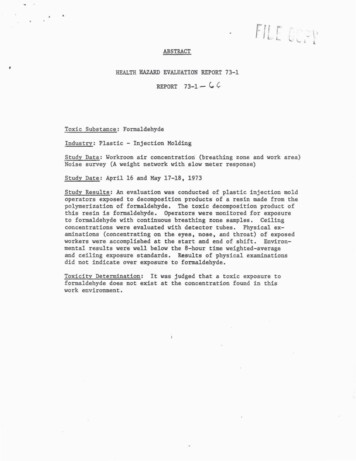
Mobility of Vise Grip PliersThis example applies Gruebler’s equation tothe determine the mobility of a vise grip plier.145143322Each revolute jointremoves two DOF.The screw jointremoves two DOF.L 5J 4 (revolute)J 1 (screw)G 1 (your hand)DOF 3*5 - 2*5 - 1*3 2The mobility of the plier is two. Link 3 can be moved relative link1 whenyou squeeze your hand and the jaw opening is controlled by rotatinglink 5.Dr. Anwar Abu-Zarifa . Islamic University of Gaza . Department of Mechanical Engineering . 2012
Punch PressSlider-Crank MechanismAs designated in the figure, there are fourlinks link 1, link 2, link 3 and link 4. Link 1acts as a crank. Link 2 acts asconnecting link, link 3 is the slider andlink 4 is ground.JointNumberFormed between links1Link 4 and Link 12Link 1 and Link 23Link 2 and Link 34Link 3 and Link 4Joint typeRevolute(or Pin)Revolute(or Pin)Revolute(or Pin)Translational or(Slider)Dr. Anwar Abu-Zarifa . Islamic University of Gaza . Department of Mechanical Engineering . 201238
Mechanisms and Structures If DOF 0, the assembly of links is a mechanism and willexhibit relative motion If DOF 0, the assembly of links is a structure and no motionis possible. If DOF 0,then the assembly is a preloaded structure, nomotion is possible, and in general stresses are present.Dr. Anwar Abu-Zarifa . Islamic University of Gaza . Department of Mechanical Engineering . 201239
Paradoxes Greubler criterion does not include geometry, so itcan give wrong prediction We must use inspectionL 5J 6G 1M 3*5-2*6-3*1 0E-quintetDr. Anwar Abu-Zarifa . Islamic University of Gaza . Department of Mechanical Engineering . 201240
Rolling cylinders even without slip (The joint between the two wheels can bepostulated to allow no slip, provided that sufficient friction is available) is anexample in which the ground link is exactly the same length as the sum of two
Text Book: R. L. Norton, Design of Machinery “An Introduction to the Synthesis and Analysis of Mechanisms and Machines”, McGraw Hill Higher Education; 3rd edition Reference Books: John J. Uicker, Gordon R. Pennock, Joseph E. Shigley, Theory of Machines and Mechanisms R.S. Khurmi, J.K. Gupta,Theory of Machines Thomas Bevan, The Theory of Machines The Theory of Machines by