Transcription
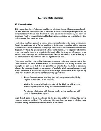
Basic Finite State MachinesWith Examples in Logisim and VerilogBy: Andrew TulineDate: June 4, 2013This is a work in Progress!IntroductionHaving recently rekindled my interest in electronics, I decided to re-learn various aspects of digital logic.This document provides some examples of the analysis and design of a few simple Finite StateMachines.What Is Covered Moore machinesMealy machinesLogisim (as in free software) based circuit designsVerilog based circuit designs using Altera’s Quartus II (the free version)Verilog based testbench using Altera/Mentor’s ModelSim (also free)What Is Not CoveredThis document assumes you are already familiar with: Boolean logicNumber systemsFlip-flop basicsTruth tablesKarnaugh mapsCombinational logicHazards (timing glitches)Ripple vs synchronous countersIn addition, this document does not cover: Verification of the designTiming analysis of the design1
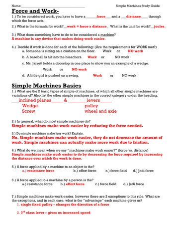
A Simple Finite State MachineWhether it be a counter, a sequence recognizer, a vending machine or an elevator, through the use ofcombinational and sequential logic, we can store information about a system in the form of a FiniteState Machine. Here’s a very simple example of a Finite State Machine that changes states without anyadditional inputs or outputs. It’s a on000110CTransitionThis simple Finite State Machine, or ‘FSM’ has 3 states, A, B and C. This will automatically transitionbetween each state with a clock signal. These states can be represented in binary with 2 bits, supportedby 2 flip-flops which would be used to store the state information. The blue arrow points to the‘starting’ state.These 3 states could also contain more than 2 bits. For example:0000111012
Although, there are only 3 states (thus 2 bits), there happen to be 3 bits of stored information, therefore3 flip-flops would be used for this FSM.In addition, you can use inputs to move from one state to the next. Let’s say we have an elevator with 2buttons, ‘Up’ and ‘Down’. This could be represented as follows:UpStartInputsMain2ndDownDownUpIf you’re on the main floor and press the ‘Up’ button, you go up. If you press it again, nothing happens.Of course, the ‘down’ button takes you down.Let’s create binary representation of the inputs and states as 01Button/InputDownUpBinaryRepresentation013
Mealy and Moore MachinesMealy and Moore machines are used to represent our elevator as finite state machines. These provide: StatesState transitionsInputsOutputsIn the previous examples, we would have used the state value as our circuit ‘output’. Shown below is aMoore machine where the output values are determined by its current state:1State/Output0/001/101InputIn this case, it’s just a coincidence that the output and state values match.4
What if you wanted to: Push the ‘1’ button to go up, and the ‘0’ button to go down, andOutput a ‘1’ every time you change floors and a ‘0’ when you don’t.This can be shown by a Mealy machine, which displays the outputs on the state transition instead of thestate itself, as shown below:1/10State1Input/Output0/00/11/0As you can see, it’s easy to represent this change with a Mealy machine, but you would requireadditional states to represent this with a Moore machine. Therefore, you might want to use a Mooremachine when outputs are just associated with the state and a Mealy machine when the outputs areassociated with an input as well as the state.5
Flip-flops We’ll UseIn order to save the state information, we’ll use flip-flops. There are several available from which tochoose, such as RS, D, T, JK, and several options for each, such as enable, preset, clear or even latches.For this article, we’ll focus on basic ‘D’ and ’T’ flip-flops. In addition, we’ll be simulating our resultantcircuits with Logisim and later with Verilog and ModelSim. See the references at the end of thisdocument for information on downloading this free software.A ‘D’ flip-flop is usually used as a register, where the next state takes on the value of the current input.A 'T’ flip-flop is usually used as a counter, where the next state toggles if the current input is a ‘1’.We can also configure a JK flip-flop as both a ‘T’ and ‘D’ as follows (with Logisim):We’ll also be using a Next State Table as shown below in order to determine the logic required in orderto create our FSM’s.Q0011Q 0101R?010S010?D0101J01?K?10T0110Note: The Survivalcraft game for the Android contains SR flip-flops, which are actually JK. As a result, youcan convert them to ‘T’ or ‘D’ and use the examples in this document in the game.6
Next State Transition TableFor each flip-flop, we’ll need to develop a good understanding of the current state values (or Q) and theinputs required to generate the next state value (or Q ).Q0011Q 0101R?010S010?D0101J01?K?10T0110In the above table, For the current state Q 1 to change in the next state to Q 1 during a clock cycle, a‘D’ flip-flop would require an input value of 1, whereas a ‘T’ flip-flop would require an input value of 0.From there, we’ll build a table of values required in order to accomplish the outputs of our FSM. Afterthat, we build Karnaugh mapping tables in order to determine the logic.7
What Our First Circuit Will Look LikeWe’ll use combinational logic to derive the ‘D’ or ‘T’ input value from the current state values. Inaddition, more advanced circuits will include input and separate output values in the logic.In1Q1In0Q0D or TD or TClock8
Example 1: Our CounterDescription: On each clock cycle, the counter will change to the next state.000011010101Let’s represent the counter states with 3 bits called Q2, Q1 and Q0. The ‘next’ states will be referred toas Q2 , Q1 and Q0 . We’ll need to create a current and next state table with these Q values as follows:Q20010Q10101Q00110Q2 0100Q1 1010Q0 1100Next, we will need to determine which type of flip-flop we’re going to use in our circuit (we’ll try both ‘T’and D). We’ll then need to create a table that shows the inputs required in order to progress to the nextstate.9
T Flip-flop VersionSince a ‘T’ flip-flop is generally used as a counter, let’s try that example first. Here’s a ‘T’ flip-flop basedtransition table:Q0011Q20010Q 0101T0110Current and Next State TableQ1Q0Q2 000111010100Q1 1010Q0 1100T Values RequiredT2T1T0011In this example The topmost Q2 is a 0, and Q2 is a 0, so the ‘T’ value required to get there will be a 0.The topmost Q1 is a 0, and the Q1 is a 1, so the ‘T’ value required will be a 1.Finally, the third Q0 entry is a 1, while the Q0 entry is a 0, so the ‘T’ value required will be a 1.Let’s fill in the State table, and include the ‘T’ value inputs for each.Q20010Current and Next State TableQ1Q0Q2 000111010100Q1 1010Q0 1100T20110T Values RequiredT1T011101110Next, we’ll need to generate Karnaugh maps (generation tables) with the Q2, Q1, Q0 outputs for each ofT2, T1 and T0.We’ll put an ‘x’ (don’t care) in each location that isn’t listed above.10
T2 Generation Table (from Q2/Q1/Q0 values)Q001000x0101Q2/Q111xx10x1T2 Q0T1 Generation Table (from Q2/Q1/Q0 values)Q001001x0111Q2/Q111xx10x1T1 1T0 Generation Table (from Q2/Q1/Q0 values)Q001001x0100Q2/Q111xx10x1T0 'Q1 (as in NOT Q1)11
Let’s create a circuit based on this design, with ‘T’ flip-flops.According to the generation tables: T2 takes on its value from Q0T1 is a 1T0 takes on its value from 'Q1All we need to do now is to toggle the clock inLogisim and watch the Q values go from: 000011101010Here’s the basic circuit from our tables:Let’s get those inputs hooked up from the appropriate pins as follows:12
As an exercise in Logisim, set the Q outputs to all the different possible states and toggle the clock.Although this circuit is quite simple, this counter may not be able to ‘reset’ itself if it starts in the wrongstate. As a result, we may have to go in and tighten the logic up by excluding some of the ‘don’t care’states in our Karnaugh map in order to make it more reliable. Good luck!D Flip-flop VersionNow, let’s try the circuit with some ‘D’ flip-flops instead.Q20010Current and Next State TableQ1Q0Q2 000111010100Q1 1010Q0 1100Again, we’ll need to generate Karnaugh maps with the Q2, Q1, Q0 statesfor each of D2, D1 and D0.We’ll put an ‘x’ (don’t care) in each location that isn’t listed above.D20100D Values RequiredD1D011011000Q0011Q 0101D0101D2 Generation Table (from Q2/Q1/Q0 values)Q001000x0101Q2/Q111xx10x0D2 Q1 & Q0D1 Generation Table (from Q2/Q1/Q0 values)Q001001x0100Q2/Q111xx10x1D1 'Q113
D0 Generation Table (from Q2/Q1/Q0 values)Q001001x0101Q2/Q111xx10x0D0 'Q2 & 'Q1 'Q2 & Q0So, what does our resultant ‘D’ flip-flop logic look like?Well, that’s not very pretty. Again, change the clock state to watch it count up through the predictedstates. Unlike our 'T’ based counter, this one should correct itself pretty quickly if put into a randomstate, but it’s not nearly as simple a design as the 'T’ version.14
Example 2: The ElevatorOur elevator from the introduction has fewer states than the counter, but does have an input to changestates as well as an output value. This incarnation is a Moore machine, where the output is just afunction of the state.10/01/1010AnalysisFirst off, we’ll need to come up with our current/next state table, which will include the Output. We’realso going to design this with ‘D’ and ‘T’ flip-flops as well as Verilog.Q00011Q0011Input0101Q 0101Q0 0101D0101Output0101D00101Q0011Q 0101T00110T011015
From the current/next state table, along with ‘D’ and ‘T’ state transition tables, we can determine therequired values of D0 and T0.D0 Table (from Q0/In)Q0Input01000111D0 InT0 Table (from Q0/In)Q0Input01001110T0 (In & 'Q0) ('In & Q0)orT0 In Q0 (as in xor)Output Table (from Q0/In)Q0Input01000111Output InHere’s our ‘D’ flip-flop version done with Logisim.Here’s our ‘T’ flip-flop version. It more complex if we didn’t see that an xor gate could be used.SummaryIt’s interesting to see how the ‘D’ flip-flop scenarios differ from the ‘T’ versions. Let’s try designing theelevator using Quartus II and Verilog next.16
The Verilog MethodThis section assumes you are already familiar with using Verilog for both basic combinational andsequential designs. See my Verilog tutorial if you aren’t.In order to design our elevator using traditional logic, we had to perform a significant amount ofanalysis, develop truth tables and Karnaugh maps and then convert it all to sequential andcombinational logic. Developing an FSM with Verilog uses a completely different approach and isactually significantly easier once you understand the template that’s used. In fact, you can go directlyfrom the Mealy/Moore diagram to your Verilog code.Altera’s Quartus II software provides a template to get you started developing a FSM on your own. To doso:1) Open or create a project in Quartus II.2) Open or create a new Verilog HDL file (and save it).3) Click on the ‘scroll’ icon as shown:4) Insert a 4 state Moore Machine as shown :17
The Quartus template provides a working 4 state Moore FSM (which I won’t duplicate). Here is the corefunctionality of this template in Verilog:module moore state machine (// Declare inputs and outputs);// Define the state register//// Define the states//// Sequential section to provide output for each state//// Sequential section to determine the next state//endmodule18
Here’s our Moore machine elevator in Verilog (called elevator.v):module elevator (input clk, in, reset,output reg [0:0] out);reg[0:0] state;// Define the state register (1 bit wide)parameter S0 0, S1 1;// Define the statesalways @ (state) begincase (state)S0:// Output depends only on the stateS1:default:endendcaseout 1'b0;// A single bit, which is ‘0’out 1'b1;// A single bit, which is ‘1’out 1'b0;always @ (posedge clk or posedge reset) begin // Determine the next stateif (reset)state S0;// Support for resetelsecase (state)S0:if (in)state S1;elsestate S0;S1:if (in)state S1;elsestate S0;endcaseendendmoduleIt might look a bit complicated at first, however this is a template that can easily be used for morecomplicated Moore machines, and you DON’T have to go through all that analysis. You can actuallydevelop the Verilog logic directly by looking at each state and entering the next state and outputs fromyour Moore machine.19
Here’s what it looks like with the Netlist RTL viewer:When you click on the yellow box, you can then see it in more detail in the State Machine viewer.Disappointingly, it does NOT represent our elevator’s functionality as expected:Let’s try it out in ModelSim to see if/how it works. Before doing so, we’ll need to create a testbench inorder to test this design. We’ll create and apply the clock along with input signals at appropriate timesand view the resultant waveforms.20
Here’s our test bench (called test1.v):// Elevator FSM test bench// timescale 1ns/1nsmodule test1 ();reg clk, in, reset;elevator dut (clk, in, reset, out);initial beginclk 0; in 0; reset 1;end#10;reset 0;in 1;clk 1;#10;#10;#10;clk 0;in 0;#10;#10;clk 1;#10;clk 0;in 1;clk 1;#10;#10;#10;clk 0;in 0;clk 1;clk 0;#10;#10;#10;#10;// Here’s the results from our waveform below// 0ns - Clear everything and assert reset//everything at 0ns. State, output 0.// 10ns - Clear reset .// 20ns - Set input.// 30ns - Assert clock. State and output change//to 1.// 40ns - De-assert clock.// 50ns - De-assert input. State and output, no//change.// 60ns - Assert clock. State and output change//to 0.// 70ns - De-assert clock.// 80ns - Assert input.// 90ns - Assert clock. State and output change//to 1. Yeah!!!!// And so on . .endmodule21
Here’s the ModelSim waveform:Summary1) Although the Quartus State Machine Viewer doesn’t show it, our elevator FSM works asdesigned in ModelSim.2) Once understood, the Moore machine Verilog template is much easier to work with than goingthrough the analysis performed for traditional logic.3) We are avoiding risky ‘x’ states with this design.22
Example 3: A ‘Gloppita’ MachineLet’s say, we’ve been provided with the Moore machine outlined below. We don’t know what it does,but it doesn’t look too difficult to analyze and turn it into We’ll develop circuits for both ‘D’ as well as 'T’ flip-flop circuits again.First off, we’ll need to come up with our current/next state table, which will include the Output as wellas the ‘D’ and ‘T’ inputs.23
Current and Next State Table (along with the Output)Q100001111Q000110011Input01010101Q1 000101xxQ0 010000xxQ0011D valuesrequiredD1D0000100100010xxxxOutput001100xxQ 0101D0101Q0011T valuesrequiredT1T0000101111000xxxxQ 0101T0110From the current/next state table, along with ‘D’ and ‘T’ state transition tables, we can determine therequired values of D1, D0, T1 and T0.24
‘D’ Flip-flop VersionLet’s analyze the ‘D’ flip-flop version first. We’ll need to determine the logic required to generate theoutputs for D1, D0 and the Output as follows:D1 Generation Table (from Q1/Q0/Input values)Q1/Q0Input00011110000x0101x1D1 (Q0 & In) (Q1 & In) (Q0 Q1) & InD0 Generation Table (from Q1/Q0/Input values)Q1/Q0Input00011110000x0110x0D0 'Q1 & 'Q0 & InOutput Generation Table (from Q1/Q0/Input values)Q1/Q0Input00011110001x0101x0Output Q0 (or even, 'Q1 & Q0)25
I tried both the Output Q0 as well as the Output ('Q1 & Q0) versions, and both work nicely.26
'T’ flip-flop version.T1 Generation Table (from Q1/Q0/Input values)Q1/Q0Input00011110000x1101x0T1 (In & Q0) ('In & Q1)T0 Generation Table (from Q1/Q0/Input values)Q1/Q0Input00011110001x0111x0T0 (In & 'Q1) Q0Output Generation Table (from Q1/Q0/Input values)Q1/Q0Input00011110001x0101x0Output Q027
Again, set the input value prior to toggling the clock for each state.28
Verilog versionmodule gloppita (input clk, in, reset,output reg [0:0] out);reg[1:0] state;// Define the state registerparameter S0 0, S1 1, S2 2;// Define the statesalways @ (state) begincase (state)S0:// Output depends only on the stateS1:S2:default:endendcaseout 2'b00;out 2'b01;out 2'b10;out 2'b00;always @ (posedge clk or posedge reset) begin // Determine the next stateif (reset)state S0;elsecase (state)S0:if (in)state S1;elsestate S0;S1:if (in)state S2;elsestate S0;S2:if(in)state S2;elsestate S0;endcaseendendmodule29
Summary This design was a few small edits different than our elevator design. This included widening thestate register, increasing the number of states by 1 and making small modifications to theoutput as well as the next state logic.Again, the State Machine Viewer didn’t represent this very well.We didn’t have to go through the full analysis in order to develop this.30
Example 4: A Mealy ElevatorOur original elevator was a Moore machine, where the outputs were tied to the state. In this case, theoutputs are a function of the state AND the input, thus we have a Mealy machine. Push the ‘1’ button to go up, and the ‘0’ button to go down.Output a ‘1’ every time you change state, and a ‘0’ when you don’t.1/1010/01/00/1AnalysisPlease have a go at this yourself.Q00011Q0011Input0101Q 0101Q0 0101D0101OutputD0Q0011Q 0101T0T011031
From the current/next state table, along with ‘D’ and ‘T’ state transition tables, we can determine therequired values of D0 and T0.D0 Table (from Q0/Input)Q0Input0101T0 Table (from Q0/Input)Q0Input0101D0 T0 Output Table (from Q0/Input)Q0Input0101Output Here’s our ‘D’ flip-flop version done with Logisim.Here’s our ‘T’ flip-flop version done with Logisim.SummaryCongratulations on designing your first Mealy machine!32
Verilog versionThis looks very similar to the Moore version, but allows for additional logic with each case comparison.If you look at the ‘always’ statements for this machine, you’ll see that:1) The next state is determined synchronously with the clock2) More importantly, the output does not wait for the clock, but asynchronously happensimmediately upon being set or reset.3) You can easily change those ‘always’ conditions.module mealy elevator (input clk, in, reset,output reg [0:0] out);reg[0:0]state;parameter S0 0, S1 1;// Declare state register// Declare states// Determine the next state synchronously, based on the current state and the inputalways @ (posedge clk or posedge reset) beginif (reset)state S0;out 1’b0;elsecase (state)S0:if (in) beginstate S1;endelse beginstate S0;endS1:if (in) beginstate S1;endelse beginstate S0;endendcaseend33
// Determine the output based only on the current state and the input (do not wait for a clock edge).always @ (state or in)begincase (state)S0:if (in) beginout 1'b1;endelse beginout 1'b0;endS1:if (in) beginout 1'b0;endelse beginout 1'b1;endendcaseendendmoduleSummaryYet again, the State Machine Viewer doesn’t show our design correctly, so let’s create a testbench inorder to ensure it works as expected. We can use the same test bench that we’d designed for the Mooreelevator.34
Here’s the testbench for our Mealy elevator with updated comments.// Elevator FSM test bench// timescale 1ns/1nsmodule test1 ();reg clk, in, reset;elevator dut (clk, in, reset, out);initial beginclk 0; in 0; reset 1;end#10;reset 0;in 1;#10;#10;clk 1;clk 0;in 0;#10;#10;#10;clk 1;clk 0;in 1;clk 1;clk 0;in 0;clk 1;clk 0;#10;#10;#10;#10;#10;#10;#10;#10;// Here’s the results from our waveform below// 0ns - Clear everything and assert reset// everything at 0ns. State, output 0.// 10ns - Clear reset .// 20ns - Set input, and output asynchronously//goes to 1.// 30ns - Assert clock. State changes to 1. Yeah!!// 40ns - De-assert clock.// 50ns - De-assert input. Output goes to 0,//while state has no change.// 60ns - Assert clock. State and changes to 0.// 70ns - De-assert clock.// 80ns - Assert input and output changes to 1.// 90ns - Assert clock. State changes to 1.// And so on . .endmoduleHere’s the resultant waveform:35
Summary Note that the output changes immediately upon the change of input, and not with the clock.Our Mealy machine works as designed.It’s still easy.36
Example 4: A Sequence RecognizerPurpose: To output a ‘1’ when the circuit sees a ‘1010’. Otherwise, output a ‘0’.Example:State TableA Nothing has been seenB A ‘1’ has been seenC A ‘10’ has been seenD A ‘101’ has been seenInput 00110101000Output 00000010100000110111/00/0A1/01/00/0CBD0/11/00/037
Let’s create our state tables for this:Current and Next State Table (along with the Output)Q100001111Q000110011Input01010101Q1 00100110Q0 01010101Q0011D valuesrequiredD1D00001100100111001Out00000010Q 0101D0101Q0011T valuesrequiredT1T00001110010010110Q 0101T0110D1 Generation Table (from Q1/Q0/Input values)Q1/Q0Input000111100011010001D1 (Q0 & 'X) (Q1 & 'Q0 & In)D0 Generation Table (from Q1/Q0/Input values)Q1/Q0Input000111100000011111D0 In38
Output Generation Table (from Q1/Q0/Input values)Q1/Q0Input000111100001010000Out Q1 & Q0 & 'In39
Next, the 'T’ flip-flop version.T1 Generation Table (from Q1/Q0/Input values)Q1/Q0Input000111100010110010T1 ('Q1 & Q0 & 'In) (Q1 & Q0 & In) (Q1 & 'Q0 & 'In)T0 Generation Table (from Q1/Q0/Input values)Q1/Q0Input000111100011011001T0 (Q0 & 'In) ('Q0 & In)Output Generation Table (from Q1/Q0/Input values)Q1/Q0Input000111100001010000Out Q1 & Q0 & 'InWell, that is one ugly bit of logic. I think I’ll pass on creating THAT in Logisim. Your turn!40
Verilog VersionWe note pretty quickly that the output isn’t just dependent on the state, but rather the state as well asinput values, so it’s a Mealy machine.module sequence recognizer (input clk, in, reset,output reg [1:0] out);reg[1:0]state;parameter S0 0, S1 1, S2 2, S3 3;// Declare state register// Declare statesalways @ (posedge clk or posedge reset) beginif (reset)state S0;elsecase (state)S0:if (in) beginstate S1;endelse beginstate S1;endS1:if (in) beginstate S2;endelse beginstate S1;endS2:if (in) beginstate S3;endelse beginstate S1;endS3:if (in) beginstate S2;endelse begin41
endendcasealways @ (state or in)begincase (state)S0:S1:S2:S3:endendcaseendstate S3;if (in) beginout 2'b00;endelse beginout 2'b10;endif (in) beginout 2'b01;endelse beginout 2'b00;endif (in) beginout 2'b10;endelse beginout 2'b01;endif (in) beginout 2'b11;endelse beginout 2'b00;endendmoduleFrom here, it should be easy to create a testbench for it.42
Summary Again, the State Machine Viewer doesn’t represent this very well.This design was a few small edits away from our elevator design. This included widening thestate register, increasing the number of states by 1 and making small modifications to theoutput as well as the next state logic.It was pretty easy to change.43
Example 5: An Old Vending MachineRequirements: Open the door for a package of Beeman’s gum after 15 cents is deposited (for Chuck Yeager).Sorry, but no change is returned.A single slot for the money.Let’s draw it:ResetCoinSensorGumReleaseFSMClockOur inputs are: Nickel / DimeResetOur output is: Open / ClosedLet’s list the valid coin input sequences: Three nickelsNickel, dimeDime, nickelTwo dimesTwo nickels, dime44
6[Open]DS8[Open]Let’s see if we can reduce those states:D0 NN5 N D10 15 [Open]D45
PresentState0 5 10 15 e0 5 10 x5 10 15 x10 15 15 x0 OutputOpen000x000000001The ‘x’ is a not-valid state as you can’t insert two coins at once.Let’s encode all this and then map it:Current and Next State Table (along with the 011xNickel010101010101xQ1 001x011x111x0Q0 010x101x011x0Out000x000x000x1Q0011Q 0101D0101D valuesrequiredD1D0000110xx011011xx101111xx00Q0011T valuesrequiredT1T0000110xx001110xx000101xx11Q 0101T011046
D1 Generation Table (from Q1/Q0/Input values)Q1/Q0D/N0001111000000101010111xxxx101101D1 ('Q1 & D) ('Q1 & Q0 & N) (Q1 & 'Q0)D0 Generation Table (from Q1/Q0/Input values)Q1/Q0D/N0001111000010001100111xxxx100101D0 ('Q0 & N) ('Q1 & Q0 & 'N) (Q1 & 'Q0 & D)Output Generation Table (from Q1/Q0/Input ut Q1 & Q047
We’ll start out with this:Here’s our resultant ‘D’ flip-flop circuit.48
Verilog Versionmodule vending machine(input clk, reset,input [1:0] in,output reg [0:0] out);reg[1:0]state;// Declare state registerparameter S0 0, S1 1, S2 2, S3 3;always @ (state) begincase (state)S0:S1:S2:S3:endendcase// Declare statesout 1'b0;out 1'b0;out 1'b0;out 1'b1;always @ (posedge clk or posedge reset) beginif (reset)state S0;elsecase (state)S0:if (in 2'b01) beginstate S1;if (in 2'b10)state S2;endS1:if (in 2'b01) beginstate S2;if (in 2'b10)state S3;endS2:if (in 2'b01) beginstate S3;49
if (in 2'b10)state S3;endS3:state S0;endcaseendendmodule50
We need a testbench for that.// Vending machine test bench// timescale 1ns/1nsmodule test1 ();reg clk, reset;reg [1:0] in;vending machine dut (clk, reset, in, out);initial beginclk 0; in 0; reset 1;#10;reset 0;#10;in 2'b01;clk 1;clk 0;in 2'b01;clk 1;clk 0;in 2'b01;clk 1;clk 0;clk 1;clk 0;#10;#10;#10;#10;#10;#10;#10;#10;#10;#10;#10;// Here’s the results from our waveform below// 0ns - Clear everything and assert reset//everything at 0ns. State, output 0.// 10ns - Clear reset .// Start off with 3 nickelsin 2'b01;clk 1;clk 0;in 2'b01;clk 1;clk 0;in 2'b10;clk 1;clk 0;clk 1;clk 0;#10;#10;#10;#10;#10;#10;#10;#10;#10;#10;#10;// Then 2 nickels and a dimein 2'b01;#10;// Then 1 nickel and a dime51
clk 1;clk 0;in 2'b10;clk 1;clk 0;clk 1;clk 0;#10;#10;#10;#10;#10;#10;#10;in 2'b10;clk 1;clk 0;in 2'b10;clk 1;clk 0;clk 1;clk 0;#10;#10;#10;#10;#10;#10;#10;#10;// Then 2 dimesin 2'b10;clk 1;clk 0;in 2'b01;clk 1;clk 0;clk 1;clk 0;#10;#10;#10;#10;#10;#10;#10;#10;// Then 1 dime and a nickel// We should also try some with input 0;endendmoduleModelSim WaveformsThe waveforms are getting to the point, where you might want to add pass/fail text.52
SummaryThis is really a 4 state Moore machine with a 2 bit input. It’s relatively straightforward when you think ofit that way. The issue is that the testing can start to become exponentially more complicated as youincrease the number of states, inputs and outputs to be tested.53
ConclusionThis is obviously not an exhaustive study of Finite State Machines, but rather an overview includingrepresentation, analysis and implementation of a few simple examples.For me, the next steps will be to learn various aspects of CPU architecture and implement one in Verilog.Best of luck,Andrew54
References Digital Design and Computer Architecture by David Money Harris & Sarah L. HarrisDigital Design Principles And Practices by John WakerlyFundamentals of Logic Design by Charles H. Roth Jr. and Larry L. KinneyLogisim, available at http://sourceforge.net/projects/circuit/Altera Quartus II web package and ASE ModelSim, available jspUC Berkely CS150 CourseBora Binary Explorer and the related ECED2200 course by Colin O’FlynnGoogle (of course)55
Date: June 4, 2013 . This is a work in Progress! Introduction . Having recently rekindled my interest in electronics, I decided to re-learn various aspects of digital logic. This document provides some examples of the analysis and design of a few simple Finite State Machines. What Is Covered Moore machines Mealy machines