Transcription
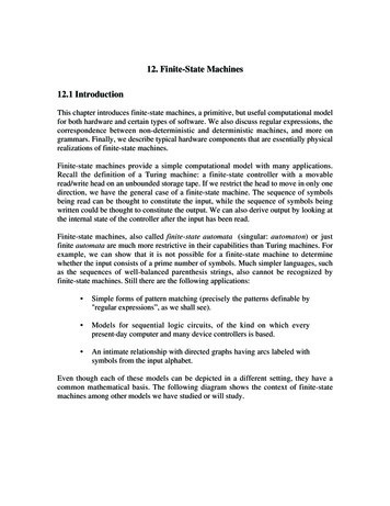
1Finite-State Machine (FSM) DesignFSMs, an important category of sequential circuits, are used frequently in designing digitalsystems. From the daily used electronic machines to the complex digital systems, FSMs are usedeverywhere. For example, in a station the vending machine which dispatches ticket uses a simpleFSM. In the complex digital systems the controlling part is most of the times implemented usingFSMs.FSMs are generally of two types.1. MEALY Machine: MEALY circuits are named after G. H, Mealy, one of the leadingpersonalities in designing digital systems. The basic property of Mealy circuits is that theoutput is a function of the present input conditions and the present state (PS) of thecircuit.2. MOORE Machine: MOORE circuits are named after E. F. Moore, another leadingpersonality in designing digital systems. The basic property of Moore circuits is that theoutput is strictly a function of the present state (PS) of the circuit.Most of the digital systems use either Moore or Mealy machine but both machines also can beused together. In initial days of digital system design when HDL languages are not discovered,Mealy or Moore machines are realized using K-Map optimization technique. The K-mapoptimization technique provides an optimized solution but it is a rigorous and lengthy process.On the contrary HDL provides an easy solution to the design of FSMs by saving design time. Inthis tutorial we will discuss design of some of the digital systems using both Mealy and Mooremachine. We will end up with a comparison between these two machines.Mealy based Sequence DetectorSequence detector is good example to describe FSMs. It produces a pulse output whenever itdetects a predefined sequence. In this tutorial we have considered a 4-bit sequence “1010”. Thefirst step of an FSM design is to draw the state diagram. The sequence detectors can be of twotypes: with overlapping and without overlapping. For example consider the input sequence as“11010101011”. Then in „without overlapping‟ style the output y will be “00001000100” and theoutput y in „with overlapping‟ style will be “00001010100”. The „with overlapping‟ style alsoconsiders the overlapping sequences. The state diagram of the “1010” sequence detector usingMealy machine in „without overlapping‟ style is shown below.
2Figure 1: Mealy based „1010‟ sequence detector without overlapping.The drawing of the correct state diagram is very crucial in designing FSMs. Though there is nofixed rule of drawing state diagrams but some comments can be made. In present state S 0, ifinput is „1‟ then the next state is S1 and if input „0‟ then the next state is the current state. It issimilar for present state S1. In present state S2 if there is a false bit, the next state is S0 and inpresent state S3 if there is a false bit, the next state is S1. From the above statement it can be saidthat if there is a false input, the next state will be the nearest similar state. It is to remember thatfor any combinations we have to reach the branch where output is „1‟. For example considerinput sequence (din) as “011010”. The sequence of next states will be “S0S1S1S2S3S0”.The „1010‟ sequence detector using Mealy machine without overlapping is realized usingVerilog. The Verilog code is given below.module melfsm(din, reset, clk, y);input din;input clk;input reset;output reg y;reg [1:0] cst, nst;parameter S0 2'b00, //all statesS1 2'b01,S2 2'b10,S3 2'b11;
3always @(cst or din) /// use posedge clk to avoid glitchbegincase (cst)S0: if (din 1'b1)beginnst S1;y 1'b0;endelsebeginnst cst;y 1'b0;endS1: if (din 1'b0)beginnst S2;y 1'b0;endelsebeginy 1'b0;nst cst;endS2: if (din 1'b1)begin
4nst S3;y 1'b0;endelsebeginnst S0;y 1'b0;endS3: if (din 1'b0)beginnst S0;y 1'b1;endelsebeginnst S1;y 1'b0;enddefault: nst S0;endcaseendalways@(posedge clk)beginif (reset)cst S0;
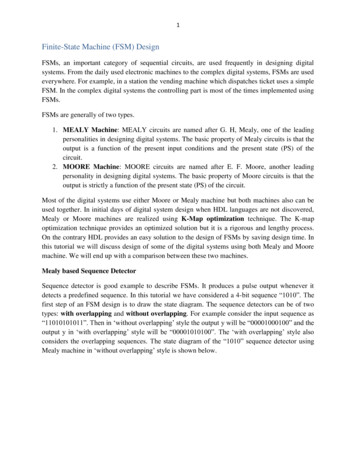
5elsecst nst;endendmoduleThe optimized logic architecture for „1010‟ sequence detector without overlapping using MealyMachine is shown below. Here instead of giving the RTL schematic we have given the K-mapoptimized block diagram for better understanding.Figure 2: „1010‟ sequence detector without overlapping using Mealy machine
6Sequence detector with overlappingFigure 3: State diagram for „1010‟ sequence detector using Mealy machine (with overlapping)The Verilog implementation of this FSM can be found in Verilog file in the download section.Moore based sequence detectorThe same „1010‟ sequence detector is designed also in Moore machine to show the differences.The state diagrams for „1010‟ sequence detector with overlapping and without overlapping areshown below.Figure 4: State diagram for „1010‟ sequence detector using Moore machine (withoutoverlapping)
7Figure 5: State diagram for „1010‟ sequence detector using Moore machine (with overlapping)The Moore machine can be designed same way as Mealy machine using Verilog. Onlydifference is that in case of Moore machine there are 5 states. Instead of output branch, there is aoutput state in case of Moore Machine. The objective is to reach the output state from any state.The Verilog codes for Moore implementations can be found in Verilog file in Download section.The logic diagram is shown below for „1010‟ sequence detector without overlapping.Figure 5: Block diagram for „1010‟ sequence detector using Moore machine (withoutoverlapping)
8A comparison can be drawn between Figure 3 and Figure 5. In Figure 3, which is the blockdiagram, of a Mealy machine, output depends on input and the current states or output of theflip-flops. Whereas in Figure 5, which is the block diagram of a Moore machine, output isfunction of only the present states or output of the flip-flops. And also there is an extra flip-flopused in case of Moore Machine.Serial Adder:Serial adder design using FSM is a popular design which is frequently used in literature. Here inthis tutorial we will design a serial adder using Mealy machine. The state diagram for the serialfull adder is shown below. There are two states defined based on carry. The state S0 is for carryequal to zero and S1 is for carry equal to 1.Figure 6: State diagram for serial full adderThe state diagram can be understood clearly from the truth table of full adder which is shownbelow.Table 1: Truth table for full adderPS cin a b sum cout NSS0 0 0 000S0S0 0 0 110S0S0 0 1 010S0S0 0 1 101S1S1 1 0 101S1S1 1 1 001S1S1 1 1 111S1S1 1 0 010S0
9module serial add(a,b,cin,reset,clk,sum,nst);output reg sum;input a,b,cin;input clk;input reset;reg cst;output reg nst; /// carry outinitial begin cst cin; end/// state assignmentparameter S0 1'b0,S1 1'b1;/// Synvhronous with clockalways @(posedge clk)begincase (cst)S0 : beginsum a b;if(a&b)nst S1;else nst cst;endS0 : beginsum (a b);if( a& b)nst S0;
10else nst cst;enddefault: nst S0;endcaseend/// reset facilityalways@(posedge clk)beginif (reset)cst S0;elsecst nst;endendmoduleVending Machine ProblemVending Machine is a practical example where FSM is used. The ticket dispatcher unit at thestations, the can drinks dispatcher at the shops are some examples of Vending machines. Here inthis tutorial we will try to understand a simple Vending machine which dispatches a can of cokeafter deposition of 15 rupees. The machine has only one hole to receive coins that meanscustomers can deposit one coin at a time. Also the machine receives only 10 (T) or 5 (F) rupeecoin and it doesn‟t give any change. So the input din can take values like1.2.3.4.din 00, no coin deposited.din 01, 5 rupee coin (F) deposited.din 10, 5 rupee coin (T) deposited.din 11, forbidden - Both coin can‟t be deposited at same time.Also a customer can deposit 15 rupees by the following ways1. 10 5 152. 5 10 153. 5 5 5 15
11If more money is deposited than 15 then the machine will be on the same state asking thecustomer to deposit right amount. The state diagram for the vending machine is shown below.Figure 7: The state diagram for the Vending machineThe PS/NS and output table for the Vending machine problem discussed above is shown below.Table 2: PS/NS and outputPresentStateS0S1S2S3Next Statedin 00 din 01 din 10S0S1S2S1S2S3S2S3S2S3S1S2module vending(T,F,reset,clk,y);output reg y;input T,F;din 000000Outputdin 010010din 100100
12input clk;input reset;wire [1:0] din;assign din {T,F};reg [2:0] cst, nst;parameter S0 2'b00,S1 2'b01,S2 2'b10,S3 2'b11;always @(posedge clk or din)begincase (cst)S0: if (din 2'b00)beginnst S0;y 1'b0;endelse if (din 2'b01)beginnst S1;y 1'b0;endelse if (din 2'b10)beginnst S2;
13y 1'b0;endS1: if (din 2'b00)beginnst S1;y 1'b0;endelse if (din 2'b01)beginnst S2;y 1'b0;endelse if (din 2'b10)beginnst S3;y 1'b1;endS2: if (din 2'b00)beginnst S2;y 1'b0;endelse if (din 2'b01)beginnst S3;
14y 1'b1;endelse if (din 2'b10)beginnst S2;y 1'b0;endS3: if (din 2'b00)beginnst cst;y 1'b0;endelse if (din 2'b01)beginnst S1;y 1'b0;endelse if (din 2'b10)beginnst S2;y 1'b0;enddefault: nst S0;
15endcaseendalways@(posedge clk)beginif (reset)cst S0;elsecst nst;endendmoduleComparison between Moore and Mealy MachineMealy MachineOutput depends on present input and presentstate of the circuit.Required less number of statesAsynchronous output generation though thestate changes synchronous to the clockFaster, output is generated on the same clockcycle.Glitches can be generated as output changedepends on input transition.Moore MachineOutput depends only on the present state of thecircuit.Required more number of states than MealymachineBoth output and state change synchronous tothe clock edgeOutput is generally produced in the next clockcycleSafer to use, because they change states on theclock edgeNote: To avoid the glitches in Mealy machine, registered Mealy machine or synchronousMealy or really Moore is used. Synchronous Mealy machines are nothing but a Moore machinewithout output state decoder.
Finite-State Machine (FSM) Design FSMs, an important category of sequential circuits, are used frequently in designing digital systems. From the daily used electronic machines to the complex digital systems, FSMs are used everywhere. For example, in a station the vending ma