Transcription
Week 3 - LectureDetailed Component DesignME 24-688 Introduction to CAD/CAE Tools
Lecture Topics Product Engineering Part 2Rapid PrototypingDesigning for Manufacturing IntroDesigning Styled ComponentsDesigning Plastic ComponentsCase Study ExamplesME 24-688 Introduction to CAD/CAE Tools
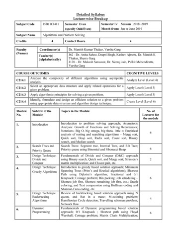
Product Lifecycle – Week oductEngineeringManufacturingEngineeringSimulation &ValidationBuild &ProduceDisposal &RecyclingMaintenance& RepairME 24-688 Introduction to CAD/CAE ToolsSales &DistributionTest & Quality
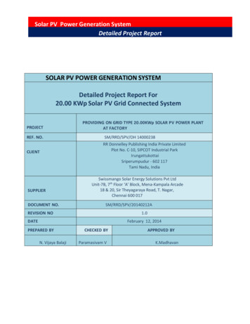
3D Design UseCNCManufacturingRapidPrototypingAutomation3D CAD ModelDesign Detailand FormVisualizationSimulation /AnalysisME 24-688 Introduction to CAD/CAE Tools
3D Design UseCNCManufacturingRapidPrototypingAutomation3D CAD ModelDesign Detailand FormVisualizationSimulation /AnalysisME 24-688 Introduction to CAD/CAE Tools
Common Terms Rapid Prototyping– General term for automaticconstruction of a physicalprototype object on a machine. Rapid Manufacturing– General term for the automatic construction of a physical object thatwill be used as a production item. 3D Printing– Process for creating 3D objects from a materials printer. Generallymore desktop and affordable machines.ME 24-688 Introduction to CAD/CAE Tools
3D Printing Applications Concept Models– Used to evaluate, optimize, andcommunicate your designs. Functional Prototypes– Allow you to test in real-world environments and make decisions. End-use Parts– Build small quantities of parts that are tough enough for production.ME 24-688 Introduction to CAD/CAE Tools
Benefits of Rapid Prototyping Time Savings– Improve Design– Increase Visualization Cost Savings / Reduction– No prototype tooling and parts– Small Qualities– Detect design flaws earlyME 24-688 Introduction to CAD/CAE Tools
Validate Design FormME 24-688 Introduction to CAD/CAE Tools
Functional PrototypesME 24-688 Introduction to CAD/CAE Tools
Considerations Tolerances– /- 0.005 inch or /- 0.0015 inch per inchwhichever is greater Build Sizes– 15” x 14” x 15” (Average)– 36” x 24” x 36” (Large) Material Properties– Wax Based Materials– Plastic Based Materials (ABS, Polycarbonate)– Metal Based Materials (Newer)ME 24-688 Introduction to CAD/CAE Tools
Companies Machine Providers– Stratasys www.stratasys.com– 3D Systems www.3dsystems.com Cubify http://cubify.com– Objet www.objet.com On Demand Service Providers– Quickpart www.quickparts.com– Proto Labs www.protolabs.com– RedEye www.redeyeondemand.comME 24-688 Introduction to CAD/CAE Tools
3D Design UseCNCManufacturingRapidPrototypingAutomation3D CAD ModelDesign Detailand FormVisualizationSimulation /AnalysisME 24-688 Introduction to CAD/CAE Tools
Design Detail and Form Complex Parts and Styled PartsME 24-688 Introduction to CAD/CAE Tools
Plastic Part Modeling Methods Solid Shell Method Surface Thicken MethodME 24-688 Introduction to CAD/CAE Tools
Designing Styles Parts Industrial design products like Autodesk Alias support rapid creation andmanipulation of complex surfaces anddevelopment of Class-A surfaces.ME 24-688 Introduction to CAD/CAE Tools
Design for Manufacturing (DFM) What is DFM?– DFM is the process of proactively designing products to optimize allthe manufacturing functions to assure the best cost and quality. Why DFM?–––––Lower development costShorter development timeFaster manufacturing start to buildLower assembly and test costHigher qualityME 24-688 Introduction to CAD/CAE Tools
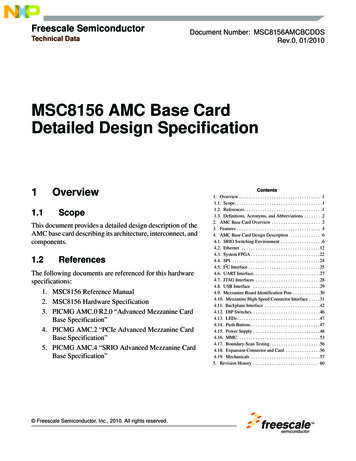
Injection Molding Manufacturing The process consists of a mold thatnormally has two halves that seal togetherfor the filling of melted plastic.ME 24-688 Introduction to CAD/CAE Tools
Injection Molding MachinesME 24-688 Introduction to CAD/CAE Tools
Good Plastic Injected Part Design Most critical factor is keep the part wallthickness uniform throughout part. Have proper draft angle on part to easeejection from mold. (0.5 – 2.0 deg.) Avoid undercuts requiring slider cores whenpossible to avoid complexity. Avoid sharp corners by adding radius.ME 24-688 Introduction to CAD/CAE Tools
ExamplesME 24-688 Introduction to CAD/CAE Tools
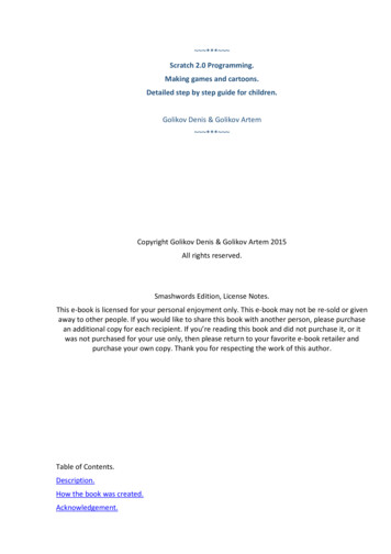
Mold Analysis Autodesk Moldflow allows you tosimulate the filling of the injection moldingprocess to predict the flow of melted plastic.ME 24-688 Introduction to CAD/CAE Tools
Moldflow Benefits Identify Possible Defects– Weld Lines & Sink Marks– Warpage & Shrinkage Optimize Manufacturing– Ensure Proper Injection Mold Design– Material Selection Simulation– Use as-manufactured material propertiesME 24-688 Introduction to CAD/CAE Tools
Computer-Cluster Projects (CP3)ME 24-688 Introduction to CAD/CAE Tools
Cluster Project 1 Guides instructions for creation various filletfeature types.ME 24-688 Introduction to CAD/CAE Tools
Cluster Project 2 Guided instructions for modeling plasticcomponent case.ME 24-688 Introduction to CAD/CAE Tools
Cluster Project 3 Guided instructions for modeling plasticcomponent case.ME 24-688 Introduction to CAD/CAE Tools
Problem Set Assignment Model detailed plastic molded part withvarious features.ME 24-688 Introduction to CAD/CAE Tools
Demo TopicsME 24-688 Introduction to CAD/CAE Tools
Creating Draft Features DraftRibbon: Model tab Modify panel DraftKeyboard Shortcut: D Draft Mini-Toolbar OptionsME 24-688 Introduction to CAD/CAE Tools
Work Features Work PointRibbon: Model tab Work Feature PointKeyboard Shortcut: . Work AxisRibbon: Model tab Work Feature AxisKeyboard Shortcut: / Work PlaneRibbon: Model tab Work Feature PlaneKeyboard Shortcut: ]ME 24-688 Introduction to CAD/CAE Tools
Creating Rest Features RestRibbon: Model tab Plastic Part RestME 24-688 Introduction to CAD/CAE Tools
Creating Grill Features GrillRibbon: Model tab Plastic Part GrillME 24-688 Introduction to CAD/CAE Tools
Creating Boss Features BossRibbon: Model tab Plastic Part BossME 24-688 Introduction to CAD/CAE Tools
Creating Lip Features LipRibbon: Model tab Plastic Part LipME 24-688 Introduction to CAD/CAE Tools
Creating Snap Fit Features Snap FitRibbon: Model tab Plastic Part Snap FitME 24-688 Introduction to CAD/CAE Tools
Creating Fillet Features RevolveRibbon: Model tab Modify FilletKeyboard Shortcut: F Extrude Mini-Toolbar Options– OK– Apply– Cancel– Selected– Radius Value– FilletME 24-688 Introduction to CAD/CAE Tools– Style– Options
Creating Rib Features RibRibbon: Model tab Plastic Part RestME 24-688 Introduction to CAD/CAE Tools
Solid Body Modeling Multi-body parts are a versatile and powerful approach toskeletal modeling. The versatility and power of multi-body parts is expanded withthe ability to derive multiple bodies into a single part, conductBoolean operations between solid bodies, split a solid body intotwo bodies, and move bodies within the part.ME 24-688 Introduction to CAD/CAE Tools
– RedEye www.redeyeondemand.com . ME 24-688 Introduction to CAD/CAE Tools 3D Design Use 3D CAD Model CNC Manufacturing Rapid Prototyping Visualization Simulation / Analysis Design Detail and Form Automation . ME 24-688 Introduction to CAD/CAE Tools Design Detail and Form Complex Parts