Transcription
Structural AnalysisLecture SeriesSA59: Calculating Slope and Deflection in BeamsUsing the Moment-Area TheoremsThis document is a written version of video lecture SA59, which can be foundonline at the web addresses listed belowEducative Technologies, re2019
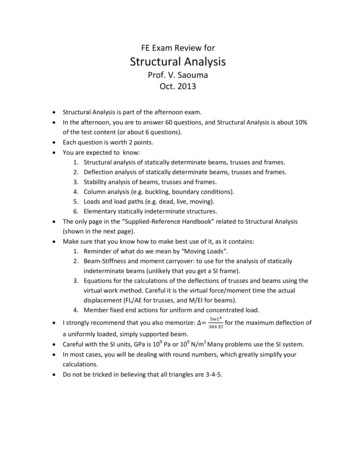
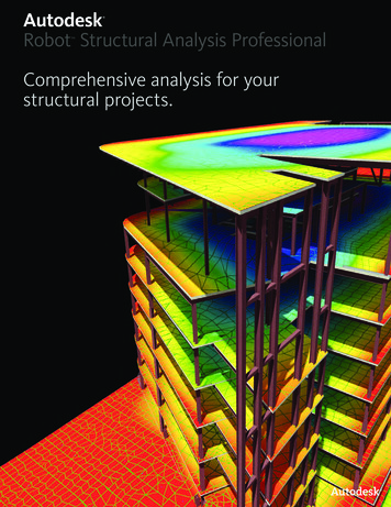
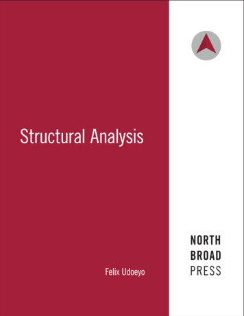
Structural Analysis – SA59The Moment-Area Method for Calculating Slope and Deflection in BeamsIn this lecture, we are going to discuss the use of the moment-area method for calculating slopeand deflection in beams.Let’s start by considering a cantilever beam subjected to a concentrated moment of 3 kN.m at itsfree end. The length of the beam is 4 meters.Figure 1: A cantilever beamNaturally, the beam is going to deflect upward, as shown in Figure 2.Figure 2: The deformed shape of a cantilever beam subjected to a concentrated momentWe refer to the deformed line along the neutral axis of the beam as its elastic curve. The slope ofthe curve we denote using θ . For example, the slope at A and B are denoted asrespectively (see Figure 2 above).θ A and θ B ,According to the moment-area method, the difference between the two slopes is equal to the areaunder the M/EI diagram between the two points. Expressed mathematically, the theorem can bewritten as follows:θB -θ A BAMdxEI[1]Please keep in mind that although we are referring to points A and B here, the theorem works forany pair of points on the beam.Let us see why this relationship holds true.Lab101.SpaceEDUCATIVE TECHNOLOGIES, LLCP a g e 2
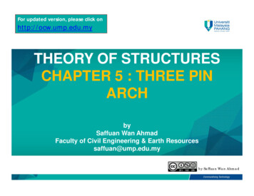
In Lecture SA22, we showed that for an infinitesimal slice of a beam (see Figure 3), thedifference between the slopes of the elastic curve at the ends of the slice can be expressed interms of the internal bending moment at that point. More precisely, we can write:dθ MdxEI[2]Where E is the modulus of elasticity of the material and I is the moment of inertia of the beamabout the axis of bending. Here we are assuming that the beam has a constant EI.Figure 3: An infinitesimal deformed beam elementIntegrating both side of Equation 2 over a specific interval, say from point i to point j along thelength of the beam, we get:jdθ i ijMdxEI[3]The left side of the equation equals: θ j -θ i . The right side of the equation is equal to the areaunder the M/EI diagram between the two points. When we apply the above expression tosegment AB of our cantilever beam, Equation 3 turns into Equation 1.Now that we know the basis for the theorem, let’s use it to calculate the rotation at the free endof the beam. The M/EI diagram for the cantilever beam is shown below.Lab101.SpaceEDUCATIVE TECHNOLOGIES, LLCP a g e 3
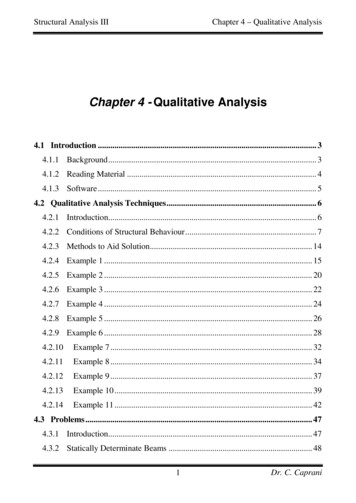
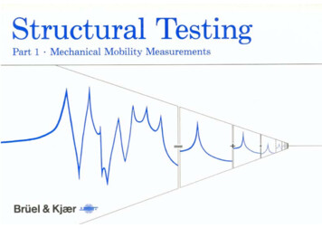
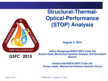
Figure 4: The M/EI diagram for a cantilever beamTherefore, the area under the diagram between A and B is:4(3/ EI) 12/ EI . Consequently,Equation 1 can be simplified to read:θ B -θ A 12/ EIAnd since the slope of the elastic curve at the fixed end of the beam is zero,determined as follows:[4]θBcan easily beθ B -0 θ B 12/ EI[5]Let’s consider another example. Suppose we wish to determine the slope of the elastic curve atθ A , we can write:the midpoint of the cantilever beam. Since we knowθ midpoint -θ A 20MdxEIThe area under the M/EI diagram for the beam segment between 0 and 2 is[6]2(3/ EI) 6 / EI ,therefore:θ midpoint -θ A θ midpoint -0 θ midpoint 6/ EI[7]Now consider a simply supported beam subjected to a concentrated load at its midpoint, asshown in Figure 5.Figure 5: A simply supported beam subjected to a concentrated loadLab101.SpaceEDUCATIVE TECHNOLOGIES, LLCP a g e 4
Suppose we wish to determine the slopes of the elastic curve at the ends of the beam. The M/EIdiagram and the elastic curve for the entire beam are shown below.Figure 6: The M/EI and elastic curve diagrams for a simply supported beamIf we label the end rotations of the beamθ A and θ B , knowing that the area under the M/EIdiagram is 18/EI, then according to the theorem we can write:6 1θ B -θ A 6( )( ) 18/ EIEI 2However, neither[8]θ A nor θ B can be calculated using the above equation, as we have one equationwith two unknowns. To be able to use the first moment-area theorem, we need to know one ofthe slopes in order to determine the other one.In this case, given the symmetrical nature of the load, we know the slope of the elastic curve atpoint C where deflection reaches its maximum value. That slope is zero, hence:6 1θ C -θ A 0-θ A θ A 3( )( ) -9/ EIEI 2Knowing[9]θ A , we can now use Equation 8 to determine θ B , as follows:Lab101.SpaceEDUCATIVE TECHNOLOGIES, LLCP a g e 5
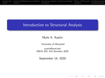
θ B -(-9) 18/ EIEI[10]Or:θ B 9/ EI[11]As we just saw, the first moment-area theorem has limited computational use. The theorem canbe used to calculate the slope of the elastic curve at a point only if we already know the slope atanother point. For example, consider the beam shown below.Figure 7: The elastic curve for a beam subjected to an asymmetrical loadingHere the load is not at the center of the beam, and the maximum deflection occurs somewherebetween points C and D. Therefore, since the exact location at which θ vanishes is not known,the first moment-area method cannot be used to determine the end slopes. For that, we need toutilize the second moment-area theorem.What is this theorem about? In essence, the second moment-area theorem states that the verticaldistance between the tangent lines at A and B, measured at B, is equal to the moment of the M/EIdiagram about B.Lab101.SpaceEDUCATIVE TECHNOLOGIES, LLCP a g e 6
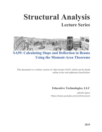
For our statically determinate beam, the M/EI diagram and the tangent lines at A and B areshown in Figure 8.Figure 8: Vertical distance between two tangent lines at the right end of a beamThe vertical distance between the two tangent lines at B is denoted asΔB/A . According to thesecond moment-area theorem, this distance is equal to the moment of the M/EI diagram aboutpoint B. Or,ΔB/A (4)(5.32 145.32 12 42.56)( )(2 ) (2)()( )(2 ) EI 23EI 23EI[12]In writing the above expression, the M/EI diagram is viewed as two right triangles, and themoment of each about B is computed by multiplying the area by the distance from its center topoint B. The two distances (moment arms) are shown in blue in the above equation.Since beam rotations are assumed to be small, we can write:θ A tan(θ A ) Or θALab101.SpaceΔB/A642.56 7.09 6EIEIEDUCATIVE TECHNOLOGIES, LLC[13][14]P a g e 7
Please keep in mind that this is a negative rotation. So, in a strict sense we should writeθ A -7.09/ EI . Now that we have θ A , we can use the first moment-area theorem to determineθ B , hence:θ B -θ ASince the area under the M/EI diagram is: 60MdxEI[15](5.32/ EI)(6)(1/ 2) 15.96/ EI , it follows that:θ B -θ A 15.96/ EIBy substituting[16]-7.09/ EI for θ A , we get: θB15.96 7.09 8.87- EIEIEIPlease note that we can also use the second moment-area theorem to determine[17]θ B . Let’s seehow. Consider the diagram shown in Figure 9. The height difference between the two tangentlines, measured at A, is labeled Δ A/B .Figure 9: Vertical distance between two tangent lines at the left end of a beamLab101.SpaceEDUCATIVE TECHNOLOGIES, LLCP a g e 8
This height can be determined by taking the moment of the M/EI diagram about point A, asshown below.Δ A/B (4)(And since5.32 145.32 12 53.20)( )(2 ) (2)()( )(4 ) EI 23EI 23EI[18]Δ A/B 6θ B , it follows that: θB53.20 8.87 6EIEI[19]Now that we know how the second moment-area theorem works, let us see why the theoremholds true. Consider an infinitesimal element in our cantilever beam, as depicted in Figure 10.Figure 10: An infinitesimal beam element at an arbitrary position in a beamThe element carries an internal bending moment of M which is causing the differential end slopedθ . The mathematical relationship between M and dθ is:dθ MdxEI[20]Without loss of generality, let us assume the element is located at distance x* from the free endof the beam. Multiplying both sides of the above equation by x*, we get:x*dθ x*MdxEI[21]If we integrate both side of the above equation from A to B, we get:Lab101.SpaceEDUCATIVE TECHNOLOGIES, LLCP a g e 9
BAx*dθ BAx*MdxEI[22]Figure 11 shows that the left side of Equation 21 equals the vertical distance between the twoend tangents at distance x* from the element.Figure 11: The vertical distance between the end tangent lines of a beam elementWhen we integrate that distance from A to B, we get the total vertical distance at B between thetwo tangent lines (lines drawn at A and B), as depicted in figure below.Figure 12: The vertical distance between the tangent lines at two distinct points in a beamNow that we know the geometric interpretation of the left side of Equation 22, let’s turn ourattention to the right side of the equation, which represents the first moment of the M/EI diagramabout point B. Therefore, we can rewrite it as follows:ΔB/A x BAMdxEI[23]Where x is the distance from the center of the M/EI diagram to point B. The above equationrepresents the second moment-area theorem. Geometrically speaking, it states that the distancebetween the two tangent lines, measured at B, is equal to the area under the M/EI diagram timesthe distance from the center of the diagram to point B.Lab101.SpaceEDUCATIVE TECHNOLOGIES, LLCP a g e 10
So, for the simply supported beam shown in Figure 7, vertical distanceΔB/A(as depicted inFigure 8) is computed by taking the moment of the area under the M/EI diagram about point B,and vertical distance Δ A/B (see Figure 9) is calculated by taking the moment of the same areaabout point A.Generally speaking, the second moment-area theorem enables us to determine both slope anddeflection in beams, whereas the first moment-area theorem can be used for calculating slopesonly.Let us determine the vertical deflection of the cantilever beam given in Figure 1 using thismethod. The M/EI diagram and the elastic curve for the beam are shown in Figure 13.Figure 13: The M/EI diagram and the elastic curve for a cantilever beamThe vertical deflection at B, which is the same asΔB/A , can be computed by taking the momentof the area under the M/EI diagram (from A to B) about B.324Δ ΔB/A (2)( )(4) EIEILab101.SpaceEDUCATIVE TECHNOLOGIES, LLC[24]P a g e 11
Now it is your turn. Use the moment-area theorems to solve the following problems.A) Determine the slope and deflection at the free end of the cantilever beam.B) Determine the beam’s deflection at B and D, and the slope of the elastic curve at C andD. The beam has a constant EI.Lab101.SpaceEDUCATIVE TECHNOLOGIES, LLCP a g e 12
Structural Analysis - SA59 The Moment-Area Method for Calculating Slope and Deflection in Beams . In this lecture, we are going to discuss the use of the moment-area method for calculating slope and deflection in beams. Let's start by considering a cantilever beam subjected to a concentrated moment of 3 kN.m at its