Transcription
HOW COMPUTERSR E A L LY W O R KAH A N D S - O NW O R K I N G SG U I D EO FT OT H ET H EI N N E RM A C H I N EMATTHEW JUSTICE
HOW COMPUTERS REALLY WORK
HOWCOMPUTERSREALLY WORKA Hands-On Guide to theInner Workings of the Machineb y Ma t t h ew J u s t i c eSan Francisco
HOW COMPUTERS REALLY WORK. Copyright 2021 by Matthew Justice.All rights reserved. No part of this work may be reproduced or transmitted in any form or by any means, electronic or mechanical, including photocopying, recording, or by any information storage or retrieval system, without the prior written permission of the copyright owner and the publisher.ISBN-13: 978-1-71850-066-2 (print)ISBN-13: 978-1-71850-067-9 (ebook)Publisher: William PollockExecuitve Editor: Barbara YienProduction Editor: Katrina TaylorDevelopmental Editor: Alex FreedProject Editor: Dapinder DosanjhCover Design: Gina RedmanInterior Design: Octopod StudiosTechnical Reviewers: William Young, John Hewes, and Bryan WilhemCopyeditor: Happenstance Type-O-RamaCompositor: Happenstance Type-O-RamaProofreader: Happenstance Type-O-RamaThe following images are reproduced with permission:Figures 7-7, 7-9, 7-10, and 7-11 ALU symbol was altered from the image created by Eadthem and is licensed underthe Creative Commons Attribution-Share Alike 3.0 Unported license -2.svg). Figures 11-3, 11-5, 11-14, 11-15, 11-16, 11-17, 12-4, 12-8, 12-9, 12-10, 13-5, 13-9 server icon is courtesy ofVecteezy.com.For information on distribution, translations, or bulk sales, please contact No Starch Press, Inc. directly:No Starch Press, Inc.245 8th Street, San Francisco, CA 94103phone: 1.415.863.9900; info@nostarch.comwww.nostarch.comLibrary of Congress Cataloging-in-Publication Data:Names: Justice, Matthew, author.Title: How Computers Really Work : a hands-on guide to the inner workings of the machine / Matthew Justice.Description: San Francisco : No Starch Press, Inc., [2020] Includesindex.Identifiers: LCCN 2020024168 (print) LCCN 2020024169 (ebook) ISBN9781718500662 (paperback) ISBN 1718500661 (paperback) ISBN9781718500679 (ebook)Subjects: LCSH: Electronic digital computers--Popular works.Classification: LCC QA76.5 .J87 2020 (print) LCC QA76.5 (ebook) DDC004--dc23LC record available at https://lccn.loc.gov/2020024168LC ebook record available at https://lccn.loc.gov/2020024169No Starch Press and the No Starch Press logo are registered trademarks of No Starch Press, Inc. Other productand company names mentioned herein may be the trademarks of their respective owners. Rather than use atrademark symbol with every occurrence of a trademarked name, we are using the names only in an editorialfashion and to the benefit of the trademark owner, with no intention of infringement of the trademark.The information in this book is distributed on an “As Is” basis, without warranty. While every precaution has beentaken in the preparation of this work, neither the author nor No Starch Press, Inc. shall have any liability to anyperson or entity with respect to any loss or damage caused or alleged to be caused directly or indirectly by theinformation contained in it.
About the AuthorMatthew Justice is a software engineer. He spent 17 years at Microsoft wherehe took on various roles, including debugging the Windows kernel, developing automated fixes, and leading a team of engineers responsible forbuilding diagnostic tools and services. He has worked on low-level software(the operating system) and on software far removed from the underlyinghardware (such as web applications). Matthew has a degree in electricalengineering. When he’s not writing code or building circuits, Matthewenjoys spending time with his family, hiking, reading, arranging music, andplaying old video games.About the Tech ReviewersDr. Bill Young is Associate Professor of Instruction in the Deptartment ofComputer Science at the University of Texas at Austin. Prior to joining theUT faculty in 2001, he had 20 years of experience in the industry. He specializes in formal methods and computer security, but often teaches computerarchitecture, among other courses.Bryan Wilhelm is a software engineer. He has degrees in mathematics andcomputer science and has been working at Microsoft for 20 years in rolesranging from debugging the Windows kernel to developing business applications. He enjoys reading, science-fiction movies, and classical music.John Hewes began connecting electrical circuits at an early age, moving onto electronics projects as a teenager. He later earned a physics degree andcontinued to develop his interest in electronics, helping school students withtheir projects while working as a science technician. John has taught electronics and physics up to an advanced level in the United Kingdom and ran aschool electronics club for children aged 11 to 18 years, setting up the websitehttp://www.electronicsclub.info/ to support the club. He believes that everyonecan enjoy building electronics projects, regardless of their age or ability.
BRIEF CONTENTSAcknowledgments . . . . . . . . . . . . . . . . . . . . . . . . . . . . . . . . . . . . . . . . . . . . . . . . . . . . xviiIntroduction . . . . . . . . . . . . . . . . . . . . . . . . . . . . . . . . . . . . . . . . . . . . . . . . . . . . . . . . . xixChapter 1: Computing Concepts . . . . . . . . . . . . . . . . . . . . . . . . . . . . . . . . . . . . . . . . . . . . 1Chapter 2: Binary in Action . . . . . . . . . . . . . . . . . . . . . . . . . . . . . . . . . . . . . . . . . . . . . . 17Chapter 3: Electrical Circuits . . . . . . . . . . . . . . . . . . . . . . . . . . . . . . . . . . . . . . . . . . . . . 31Chapter 4: Digital Circuits . . . . . . . . . . . . . . . . . . . . . . . . . . . . . . . . . . . . . . . . . . . . . . . 53Chapter 5: Math with Digital Circuits . . . . . . . . . . . . . . . . . . . . . . . . . . . . . . . . . . . . . . . . 73Chapter 6: Memory and Clock Signals . . . . . . . . . . . . . . . . . . . . . . . . . . . . . . . . . . . . . . 91Chapter 7: Computer Hardware . . . . . . . . . . . . . . . . . . . . . . . . . . . . . . . . . . . . . . . . . . 117Chapter 8: Machine Code and Assembly Language . . . . . . . . . . . . . . . . . . . . . . . . . . . . 137Chapter 9: High- Level Programming . . . . . . . . . . . . . . . . . . . . . . . . . . . . . . . . . . . . . . . 159Chapter 10: Operating Systems . . . . . . . . . . . . . . . . . . . . . . . . . . . . . . . . . . . . . . . . . . 193Chapter 11: The Internet . . . . . . . . . . . . . . . . . . . . . . . . . . . . . . . . . . . . . . . . . . . . . . . . 233Chapter 12: The World Wide Web . . . . . . . . . . . . . . . . . . . . . . . . . . . . . . . . . . . . . . . . 261Chapter 13: Modern Computing . . . . . . . . . . . . . . . . . . . . . . . . . . . . . . . . . . . . . . . . . . 291Appendix A: Answers to Exercises . . . . . . . . . . . . . . . . . . . . . . . . . . . . . . . . . . . . . . . . 319Appendix B: Resources . . . . . . . . . . . . . . . . . . . . . . . . . . . . . . . . . . . . . . . . . . . . . . . . 333
11THE INTERNETSo far, we’ve focused on computing thatoccurs on a single device. In this chapterand the next, we look at computing thatspans multiple devices. We’re going to examinetwo significant innovations in computing, the internetand the world wide web, which are not the same thing!This chapter focuses on the internet, and we begin bydefining key terms. Then we look at a layered modelof networks and dig into some of the foundationalprotocols used on the internet.Networking Terms DefinedTo discuss the internet and networks in general, you first need to becomefamiliar with some concepts and terms, which we cover here. A computer
network is a system that allows computing devices to communicate witheach other, as illustrated in Figure 11-1. Networks can be connected wirelessly, using technologies like Wi- Fi, which transmits data using radio waves.Networks can also be connected with cables, such as copper wiring or fiberoptics. Computing devices on a network must use a common communicationsprotocol, a set of rules that describe how information is to be exchanged.Figure 11-1: A computer networkThe internet is a globally connected set of computer networks thatall use a suite of common protocols. The internet is a network of networks,connecting networks from various organizations all around the world, asshown in Figure 11-2.Figure 11-2: The internet: a network of networks234Chapter 11
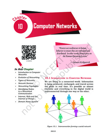
A host or node is a single computing device attached to a network. A hostcan act as a server or a client on the network, or sometimes both. A networkserver is a host that listens for inbound network connections and providesservices to other hosts. Examples are a web server and an email server. A network client is a host that makes outbound connections and requests servicesfrom network servers. Example clients are smartphones or laptops runningweb browsers or email apps. A client makes a request to a server, and the serverreplies with a response, as illustrated in Figure 11-3.RequestResponseClientServerFigure 11-3: A client makes a requestto a server, and the server respondsThe term server, as just used, refers to any device that accepts inboundrequests and provides services to clients. However, server can also refer to aclass of computer hardware that’s specifically intended to act as a networkserver. These specialized computers are physically designed to be mountedinto racks of computers in a datacenter and often include hardware redundancy and management capabilities not found in a typical PC. However, anydevice with the right software can act as a server on a network.The Internet Protocol SuitePhysically connecting the networks of the world isn’t enough to allow thedevices on those networks to communicate with each other. All participating computers need to communicate in the same way. The internet protocolsuite standardizes the method of communication on the internet, ensuringthat all devices on the network speak the same language. The two foundational protocols in the internet protocol suite are Transmission ControlProtocol (TCP) and Internet Protocol (IP), collectively known as TCP/IP.Network protocols operate in a layered model, and an implementation ofsuch a model is referred to as a network stack (not to be confused with a stackin memory, as covered in Chapter 9). The protocols at the lowest layer interact with the underlying networking hardware, whereas applications interactwith protocols in the upper layers. Protocols in the intermediate layers provide services such as addressing and reliable delivery of data. A protocol at acertain layer doesn’t have to concern itself with the entire networking stack,only the layers with which it interfaces, simplifying the overall design. This isanother example of encapsulation.The Internet235
The internet protocol suite is designed around a four- layer model. Thisis sometimes called the TCP/IP model. The four layers of the TCP/IP model,starting from the bottom up, are the link layer, the internet layer, the transport layer, and the application layer, as shown in Figure 11-4.Application layerTransport layerInternet layerLink layerFigure 11-4: The internetprotocol suite model ofnetworkingOSI — A NOTHE R NE T WORK MODE LAnother commonly used model for network protocols is the Open SystemsInterconnection (OSI) model. The OSI model divides protocols into seven layersrather than four. This model is often referenced in technical literature, but theinternet is based on the internet protocol suite, so this book focuses on the TCP/IP model.These networking layers represent an abstraction, a model for us touse when discussing the operation of the internet. In practice, each layer isrealized with specific networking protocols. Each network layer representsa scope of responsibilities, and protocols must fulfill the responsibilities oftheir assigned layer. Table 11-1 provides a description of each layer.Table 11-1: Description of the Four Layers of the Internet Protocol Suite236Chapter 11LayerDescriptionExample protocolsApplicationProtocols that operate at the application layerHTTP, SSHprovide application- specific functionality, suchas sending an email or retrieving a web page.These protocols accomplish tasks that end users (orbackend services) wish to complete. Applicationlayer protocols structure the data used in process- to- process communication across a network. All thelower layer protocols exist as “plumbing” to support the application layer.
LayerDescriptionExample protocolsTransportTransport layer protocols provide a communications channel for applications to send and receivedata between hosts. An application structures dataaccording to an application layer protocol andthen hands off that data to a transport layer protocol for delivery to a remote host.TCP, UDPInternetInternet layer protocols provide a mechanismfor communicating across networks. This layer isresponsible for identifying hosts with addressesand enabling the routing of data from network tonetwork across the internet. The transport layerrelies on the internet layer for addressing androuting.IPLinkLink layer protocols provide a way to communicate on a local network. Protocols at this layerare closely associated with the type of networking hardware on a local network, such as Wi- Fi.Protocols at the internet layer rely on link layer protocols to communicate on a local network.Wi- Fi, EthernetProtocols at each layer communicate with the protocols in adjacentlayers. An outgoing transmission from a host travels down through thenetwork layers, from an application layer protocol, to a transport layerprotocol, to an internet layer protocol, and finally to a link layer protocol.An incoming transmission to a host travels up through the network layers,reversing the order just described.Although network hosts (such as a client or server) make use of protocols from all four layers, other types of networking hardware (such asswitches and routers) only use protocols associated with lower layers. Suchdevices can perform their jobs without bothering to examine the higherlayer protocol data contained in a network transmission.An outgoing request from a client to a server, and its relationship tothe networking layers, is illustrated in Figure 11-5.ClientSends requestApplicationTransportInternetLinkRouter ARoutes request fromNetwork 1 to Network 2Routes request fromNetwork 2 to Network 3InternetLinkNetwork 1ServerReceives requestRouter BInternetLinkNetwork 2ApplicationTransportInternetLinkNetwork 3Figure 11-5: A network request travels through various network layersThe Internet237
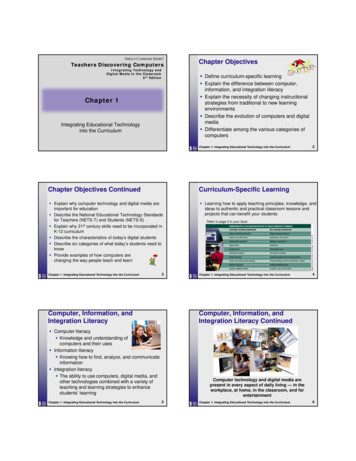
Let’s walk through the flow of Figure 11-5. An application on the clientdevice forms a request using an application layer protocol. That requestis handed off to a transport layer protocol, then to an internet layer protocol, and finally to a link layer protocol. All of this happens on the clientdevice. At this point the request is transmitted onto the local network,labeled Network 1 in the diagram. The request makes its way across theinternet, going from network to network. In this example, Router A routesthe request from Network 1 to Network 2, and Router B routes the requestfrom Network 2 to Network 3. Once the request reaches the destinationserver, it works its way up through the networking protocols, starting with alink layer protocol, and ending at an application layer protocol. A processrunning on the server receives the request, which is formatted accordingto the application layer protocol originally used by the client. The serverprocess interprets the request and responds in an appropriate manner.Let’s now take a look at each layer, starting from the bottom.Link LayerThe lowest level of the internet protocol suite is the link layer. The physicaland logical connections between hosts are known as network links. Linklayer protocols are used by devices on the same network to communicatewith each other. Each device on a link has a network address that uniquelyidentifies it. For many link layer protocols, this address is known as a mediaaccess control address (or MAC address). Link layer data is divided into smallunits known as frames, each including a header describing the frame, a payload of data, and finally, a frame footer used to detect errors. This is illustrated in Figure 11-6.Link layerframeFrameheaderFrame dataFramefooterFigure 11-6: A link layer frameThe frame header contains source and destination MAC addresses. Theheader also includes a descriptor of the type of data carried in the framedata section.If your home has a Wi- Fi network, Wi- Fi is the link between the hostson your network. The Wi- Fi protocol, defined by the IEEE 802.11 specifications, doesn’t know or care what type of data is being sent over the wirelessnetwork; it simply enables communication between devices. Each deviceconnected to the Wi- Fi network has a MAC address and receives frames sentto its address. MAC addresses are only useable on a local network; a computer on a remote network cannot directly send data to a MAC address onyour local network.Another notable link layer technology is Ethernet, used for wired physical connections. Ethernet is defined by the IEEE 802.3 standards. Ethernettypically uses a cable with pairs of copper wires inside that ends in a connector commonly known as RJ45, shown in Figure 11-7.238Chapter 11
Figure 11-7: The cable commonly used for EthernetAll devices connected to the internet participate in the link layer. Thisis required, since it’s the link layer that provides connectivity (either wiredor wireless) to a local network. A host, like a laptop or smartphone, participates in all layers, but certain networking devices operate at the link layeronly. The most basic example of this is a hub. A network hub is a networkingdevice that connects multiple devices on a local network without any intelligence regarding the frames being sent. A simple hub might provide multiple Ethernet ports for connecting devices. The hub simply retransmits everyframe it receives on one physical port to all its other ports. A more intelligent link layer device is a network switch, which examines the MAC addressesin the frames it receives and sends those frames to the physical port wherethe device with the destination MAC address is connected.NOTEPlease see Project #29 on page 254, where you can look at link layer devices andMAC addresses.Internet LayerThe internet layer allows data to travel beyond the local network. The primary protocol used in this layer is simply called Internet Protocol (IP). Itenables routing, the process of determining a path for data that’s transmitted between networks. Every host on the internet is assigned an IP address, anumber that uniquely identifies the host on the global internet. It’s also possible to have private IP addresses that aren’t directly exposed on the internet. IP addresses are usually assigned by a server on the local network, anda device’s IP address typically changes when it connects to a new network.We’ll cover more on address assignment and private IP addresses later.Data sent over the internet layer is called a packet, which is enclosed ina link layer frame. Figure 11-8 illustrates the idea that a packet fits within aframe’s data section.The IP packet header contains a source IP address and a destination IPaddress. The header also includes information that describes the packet,such as the IP version in use and the header length. The data section of theIP packet contains the payload that the IP layer is carrying.The Internet239
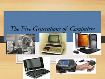
Internet layerpacketLink layerframePacketheaderFrameheaderPacket dataFrame dataFramefooterFigure 11-8: A packet is contained in the data section of a frameTwo versions of Internet Protocol are in use on the internet today.Internet Protocol Version 4 (IPv4) is the dominant version in use, and the otheractive version is Internet Protocol Version 6 (IPv6). You may wonder what happened to IPv5. No such protocol ever existed, but an experimental protocolcalled Internet Stream Protocol identified its IP version as 5, and so IPv5 wasskipped when the successor to IPv4 was developed. A significant differencebetween IPv4 and IPv6 is the size of an IP address. An IPv4 address is 32 bitsin length, whereas an IPv6 address is 128 bits. This difference allows for avastly larger number of addresses with IPv6. This change in address size ismeant to help deal with the relatively short supply of IPv4 addresses. In thisbook, we focus on IPv4 addresses (and just refer to them as IP addresses), asthey are still the primary means of addressing on the internet today.A 32-bit IP address is typically displayed in dotted decimal notation,meaning the 32 bits are separated into four groups of 8 bits each, the 8-bitnumbers are displayed in decimal (rather than hexadecimal or binary), andthe four decimal numbers are separated by periods (dots). An example IPaddress, displayed in dotted decimal notation, is 192.168.1.23. Each 8-bitdecimal number can be referred to as an octet.Computers connected to the same local network have IP addresses thatbegin with the same leading bits and are said to be on the same subnet.Computers that are on the same subnet are able to communicate directlywith each other at the link layer because they are operating on the samephysical network. Computers that are on different subnets must send theirtraffic through a router, a device that connects subnets and operates at theinternet layer.Subnetting divides the IP address into two parts: the network prefix,which all devices on the same subnet share, and the host identifier, which isunique to a host on that subnet. The number of bits included in the network prefix varies based on the network configuration.Let’s look at an example. Assume a subnet uses a 24-bit network prefix,leaving us with 8 bits to represent the host. Also assume that a host on thissubnet uses the example IP address from earlier—192.168.1.23. Giventhis IP address and network prefix, the IP address is divided as shownin Figure 11-9.In this example, all hosts on the local subnet have an IP address thatbegins with 192.168.1. Each host has a different value for the last octet, with 23being assigned to this specific host. This example uses a 24-bit prefix length,meaning the prefix neatly aligns with the first three octets of the IP address.240Chapter 11
This makes for a nice example, but the prefix length doesn’t always align withan octet boundary. A 25-bit prefix, for example, would also include the first bitof the last octet, leaving only 7 bits for identifying the host.24 leading bitsidentify the network11000000 10101000 000000018 bits identifythe host00010111192.168.1.2324-bitnetwork prefix8-bithostFigure 11-9: An example IP address using a24-bit network prefixThe number of bits reserved for the network prefix is commonlyexpressed in one of two ways. Classless Inter- Domain Routing (CIDR) notation lists an IP address followed by a slash (/), and then the number of bitsused for the network prefix. In our example this would be 192.168.1.23/24.Another common way to represent the number of prefix bits is with a subnetmask, a 32-bit number where a binary 1 is used for each bit that’s part of thenetwork prefix and a 0 is used for each bit that’s part of the host number.Subnet masks are also written in dotted decimal notation, so our exampleof a 24-bit network prefix would result in a subnet mask of 255.255.255.0, asshown in Figure 11-10.A binary 1 represents a bit thatis part of the network prefix0 represents abit that is partof the host ID11111111 11111111 11111111 00000000255.255.255.0Figure 11-10: A 24-bit network prefix expressedas a subnet maskLet’s look at how this is useful in practice. Say your computer has an IPaddress of 192.168.0.133 and a subnet mask of 255.255.255.224, or, expressedin CIDR notation, 192.168.0.133/27. Your computer wishes to connect toanother computer with an IP address of 192.168.0.84. As mentioned earlier,two computers can communicate directly if they are on the same subnet,and if not, they must go through a router. So your computer must determineif the other computer is on the same subnet. How can it do this?The Internet241
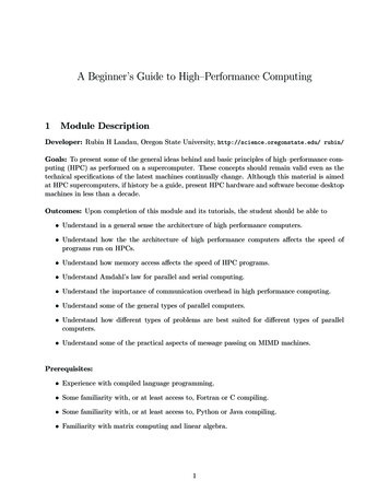
Performing a bitwise logical AND of an IP address and its subnet maskproduces the first address in a subnet. This first address, where the hostbits are all 0, serves as an identifier for the subnet itself. This is commonlyreferred to as the network ID. Two computers that share a network ID areon the same subnet. A host can perform this AND operation against bothits own IP address and the IP address it wishes to connect to, to see if theyshare a network ID and thus are on the same subnet. Let’s try this with ourexample computer’s IP address, as shown here:IP 192.168.0.133 11000000.10101000.00000000.10000101MASK 255.255.255.224 11111111.11111111.11111111.11100000AND 192.168.0.128 11000000.10101000.00000000.10000000 The network IDNow perform the same operation for the second computer in ourexample:IP 192.168.0.84 11000000.10101000.00000000.01010100MASK 255.255.255.224 11111111.11111111.11111111.11100000AND 192.168.0.64 11000000.10101000.00000000.01000000 The network IDAs you can see from this example, this operation produced two different network IDs (192.168.0.128 and 192.168.0.64). This means that thesecond computer is not on the same subnet as your computer. To communicate, these computers need to send their messages through a router connecting the two subnets.E X E RCISE 11-1: W HICH IPS A RE ON THE S A ME SUBNE T ?Is IP address 192.168.0.200 on the same subnet as your computer? Assumeyour computer has an IP address of 192.168.0.133 and a subnet mask of255.255.255.224.Here’s another way to look at this: the network prefix describes the rangeof addresses that can be used on a subnet. The first address in that range isdefined as the network prefix bits followed by all binary 0s for the host identifier. Continuing with our example computer at 192.168.0.133, the first addresson its subnet is 192.168.0.128. The last address in the range is the network prefix bits followed by all binary 1s for the host identifier. In our example that’s192.168.0.159. The first and last addresses have special meanings—the firstidentifies the network, the last is the broadcast address (used for sending a message to all hosts on the subnet). All the addresses in between can be used forhosts on the subnet. Our example IP address of 192.168.0.133 is clearly in thisrange (from 192.168.0.128 to 192.168.0.159), while the other computer withan IP address of 192.168.0.84 is outside this range.You can also use the number of bits reserved for the host identifier todetermine how many IP addresses are available for hosts on a subnet. In242Chapter 11
our example, 27 bits are reserved for the network prefix, leaving 5 bits forhost identifiers. These 5 bits give us 32 possible host addresses, since 25 is32. However, as mentioned earlier, the first and last addresses have specialpurposes, so really only 30 hosts can be identified using this network prefix.This aligns with our earlier findings: the first host identifier is 128, and 128 32 gives us 160, the first address in the next subnet, so 159 would be thelast host in our range.NOTEPlease see Project #30 on page 255, where you can look at the internet layer usingyour Raspberry Pi.Transport LayerThe transport layer provides a communications channel that applications mayuse to send and receive data. There are two commonly used transport layerprotocols: Transmission Control Protocol (TCP) and User Datagram Protocol(UDP). TCP provides a reliable connection between two hosts. It ensures thaterrors are minimized, data arrives in order, lost data is resent, and so forth.Data sent with TCP is known as a segment. On the other hand, UDP is a “besteffort” protocol, meaning its delivery is unreliable. UDP is preferred whenspeed is valued over reliability. Data sent with UDP is known as a datagram.Both protocols have their place, but to keep things simple, I cover only TCPfor the remainder of the chapter. Figure 11-11 illustrates the idea that a TCPsegment fits within a packet’s data section, which in turn fits within a frame’sdata section.As we saw earlier, the link layer includes a destination MAC addressin the frame header to identify a local network interface, and the internetlayer includes a destination IP address in the packet header to identify thehost on the internet. That’s enough information to get a packet to a specificdevice on the internet. Once a packet has reached its destination host, thetransport layer header includes a destination network port number that identifies the specific service or process that will receive the data. A host with asingle IP address can have multiple active ports, each used for performing adifferent type of activity on the network.SegmentheaderTransport layersegmentPacketheaderInternet layerpacketLink layerframeFrameheaderSegment dataPacket dataFrame dataFramefooterFigure 11-11: A TCP segment is contained in the data section of an IP packetTo use an analog
ing computers need to communicate in the same way. The . internet protocol suite. standardizes the method of communication on the internet, ensuring that all devices on the network speak the same language. The two foun-dational protocols in the internet protocol suite are. Transmission Control Protocol (TCP) and . Internet Protocol (IP)