Transcription
African Journal of AgriculturalResearchVol. 9(1), pp. 1-7, 2 January, 2014DOI: 10.5897/AJAR2013.6983ISSN 1991-637X 2014 Academic Journalshttp://www.academicjournals.org/AJARFull Length Research PaperSimulation of air flow in cold chambers using theopenfoam computational fluid dynamics (CFD)softwareJose de Castro Silva, Barbara Janet Teruel Mederos* and Luiz Antonio RossiSchool of Agricultural Engineering, University of Campinas - UNICAMP, SP, Brazil.Accepted 30 October, 2013This work applied the mathematical models already implemented in the OpenFOAM computationalfluid dynamics (CFD) software, to simulate two proposed air distributions inside cold chambers. TheOpenFOAM software was chosen because of the absence of licensing costs associated with its use,compared to the major commercial CFDsoftwares available. In the pre-processing phase, we used thefree Google SketchUp software for the virtual design of the prototypes, and the free enGrid softwarefor the discretization of these virtual prototypes; later the resulting grids were used, by theOpenFOAM , in the post-processing phase.Key words: Air flow distribution, refrigeration, foods.INTRODUCTIONThe refrigerated storage, using vapor compressionrefrigeratedchambers, which causes a decrease in boththe air and products temperature, is the most commonlyused method for preserving food with their desirablecharacteristics; thus, reducing the loss of quality, andincreasing the their shelf life (Ashrae, 2009). The bestresults from a proper preservation are obtained when therecommended temperature for each vegetable ismaintained with fewer fluctuations, as well as theappropriate distribution of cooling air. Moreover, theremust be adequate dimensioning of the cooling systems;thus, avoiding the risk of decreasing the life of theequipment (Furlan and Marques, 2007; Flores-Cantillano,2011).The proper design and operation of a cold chamber canrepresent a significant improvement in the reduction ofcosts, resulting in profits for the producer. Besides thetemperature and relative humidity, distribution and airvelocity of the cold air also have a direct effect on theheat transfer rates; directly affecting the cooling time,which in turn affects the quality and shelf life of theproduce. Within a refrigerated environment, thetemperature levels and their uniformity are directlygoverned by the airflow patterns. The temperaturemaintenance is essential during the transport and storageof a refrigerated cargo in order to preserve the shelf life,safety, and quality of perishable food products (Moureh etal., 2009). The computational fluid dynamics or CFDbegan in the late 1970s and early 1980s, where the flowswith warlike interests were the primary focus, inparticular, the displacement of air around aircraft andprojectiles. For the flow of fluids (gases and liquids), themathematical models are established based on partialdifferential equations of conservation of momentum,*Corresponding author E-mail: barbarat@feagri.unicamp.br
2Afr. J. Agric. Res.mass and energy (Souza, 2011). The use of computers inconjunction with the experimental facilities, are an idealinteraction, which enhances the analysis of fluiddynamics (Krause, 1985).The use of simulation software allows the solution ofmany scientific projects and operational problems withouteither stopping machinery or causing production losses.The reduction of time and number of experiments on testbenches allows for considerable savings in developingnew projects or updating the ones already in operation.Therefore, to ensure consistent simulation results, it isnecessary to validate them with experimental ones(Souza, 2011). According to Djunaedy et al. (2003) andLuo and Roux (2004), with the advancements incomputer technology, the use of simulation in fluiddynamics promoted a reduction in cost during the projectanalysis phase of research.The CFD techniques are helpful in obtaining predictionsof velocity and temperature distribution of indoor air,having an important role in improving designs ofventilation systems (Awbi, 1989). Gan (1995) comparedheating and cooling systems for air conditioners, thesimulations showed that the floor vent is more efficientthan the conventional systems with outlets for ceilingdiffusers. The CFD tools have been used for many yearsin the analysis of ventilation systems designs forbuildings, and in assessing ventilation parameters andenvironmental settings for the air flow in air conditioningsystems with floor vents (Nielsen, 2004). According toFortuna (2000), it is a mistake to think that the CFD willreplace experimental techniques and theoretical analysis.The CFD is an assisting tool in the understanding of thephenomena.Fukuyo (2004) applied the computational simulation toanalyze the relationship between occupations andthermal comfort within working environments. The resultshave shown that the creation of an automatic controlsystem for the cooling system in conjunction withpreventive maintenance scheduled by the technicalsupport would be the ideal way of improving systemefficiency. Jian et al. (2006), used computational tools topre-analyze projects of the entry and exit angles for theair flows inside air conditioned environments,and with thehelp of a CFD tool, concluded that the elevation of theentry angle and reduction of the exit angle contribute to abetter cooling environment, as well as the comfort for theoccupants. The application of computational fluiddynamics in the agricultural sector is becomingincreasingly important. Over the years, the versatility,ease of use and accuracy offered by the CFD led to itswider acceptance within the agricultural engineeringcommunity. Besides the refrigerated storage, the CFD isnow regularly used to solve environmental problems ingreenhouses and livestock facilities (Norton et al., 2007).Numerous studies have elucidated the benefitsassociated with the even distribution of air flow in animaland plant systems (Boulard et al., 2002; Gebremedhinand Wu, 2005). In animal production, control over the airflow is needed to remove moisture and gases frommanure, and to provide shelterfrom cold temperatures,rain and radiation. These analyzes provide a significantimprovement, making the environments healthier andmore productive for both the animals and the workers(Spoolder et al., 2000). This shows that in the ambiencearea as well, the prior knowledge of the principlesgoverning the distribution of internal climate variablesthrough a CFD tool is indispensable for the design ofproduction systems or to optimize its performance.Tassou and Xiang (1998), Hoang et al. (2000), Nahoret al. (2005) and Xie et al. (2006) performed simulationsin cold chambers with the evaporator in the conventionalposition, showing the existence of areas with stagnantair, and large variations in the air flow. The air flowanalysis showed that the CFD can be used in theanalysis of designs; however, it did not provideinformation on how to improve the air distribution withinthe cold chamber. With the complexity of temperaturehomogenization, fruits are stored at different stages ofmaturation, which is very detrimental to their marketing,seeing that they do not follow a maturation pattern.Ho et al. (2010) who studied the distribution of airpressure and temperature inside a cold chamberconcluded that the addition of evaporators, whichincrease the air flow, will help to minimize thetemperature fluctuations. With the complexity oftemperature homogenization, fruits are stored at differentstages of maturation, which is very detrimental to theirmarketing, seeing that they do not follow a maturationpattern. Besides the use of CFD tools for the analysis ofair flow in air conditioning systems and cold chambers,Cortella et al. (2001), Cortella (2002), Gaspar et al.(2003), Gaspar and Pitarma (2005), D'Agaro et al.(2006), Yan-Li et al. (2007) and Gaspar et al. (2012), alldemonstrated the use of CFD software to analyze airflowin refrigerated display cabinets used in supermarkets.Cortella et al. (2001) performed experimentalmeasurements of temperature and air velocity, in order tovalidate the numeric model predictions. The goal was tosimulate the phenomena of heat and mass transfer inopen vertical refrigerated display cabinets; themathematical model implemented in the CFD softwareaccounted for the turbulent, non-isothermal 2D flow, andfor the steady state heat transfer process. According toCortella (2002) and Lu et al. (2007), the refrigerateddisplay cabinet is the weakest link in the cold chain;therefore, researches seeking to improve this equipmentcan impact on the efficiency of the whole chain. However,it is important to add that the cold chambers, studied inthis article, are connected to all the cold chain stages;thus, making them the most important equipment in theentire chain.Gaspar et al. (2003) in a comparison between two commercial CFD software’s; the PHOENICS and the FLUENT , concluded that the PHOENICS is superior in
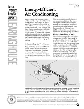
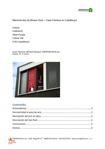
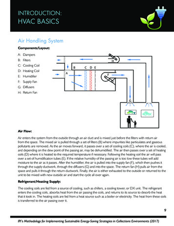
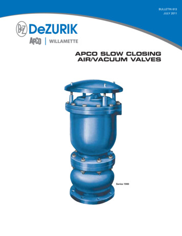
Silva et al.3Figure 1. Show the sequence of the simulation process.the diversity of physical and mathematical models, itpresents major facilities in the construction of thecomputational grid, and in the ability of using largerquantities of mathematical models. Now, the FLUENT issuperior in the ease of use due to the versatility andsimplicity of its interface, with higher velocity ofconvergence of solution, and relatively lower absoluteerror to the experimental values.Gaspar and Pitarma (2005) used the PHOENICS tosimulate and visualize the flow and heat transfer in therefrigerated space from the refrigerated display cabinet,testing alternative configurations corresponding to apreliminary study of optimization. By comparing thenumerical and experimental results for the temperature, itcan be concluded that the simulation model can predict,with appropriate accuracy, the thermal performance ofthis equipment. It is noteworthy that Gaspar et al. (2003)and Gaspar and Pitarma (2005), used the same type ofequipment (refrigerated display cabinets) for theexperimental analyzes.The comparison between the CFD results and theexperimental data, performed by D'Agaro et al. (2006),and Gaspar et al. (2012), demonstrate that a 2Dcomputer simulation is totally inadequate for suchconfigurations, while the 3D simulations are closer to thereal phenomena; therefore, the 3D simulation is a farbetter option for analyzing the engineering design inrefrigerated display cabinets. The work assumes that theuse of a new configuration for the distribution of airthrough the evaporator in the cold chamber makes itpossible to minimize temperature differences betweenthe hot and cold zones.MATERIALS AND METHODSOpenFOAM ApplicationsThe OpenFOAM is basically a set of C libraries using the finitevolume method (FVM) developed on the Linux platform, allowingelements to simulate 3D geometries, unstructured grids with anarbitrary number of faces and turbulence models. The OpenFOAM was chosen because it is free, while the major commercialCFDsoftwares such as the FLUENT and the CFX owned byANSYS and the PHOENICS owned by CHAM carry licensing fees.Simulation stepsIn the pre-processing step, we used the free Google SketchUp software for the virtual design of the prototypes, and the freeenGrid software (Figure 2) for the discretization of these virtualprototypes and to generate the grids; later the resulting grids wereused in the post-processing phase by the OpenFOAM (Figure 3).Figure 1 shows the sequence of the simulation process.Directory of structures and filesFigure 4 shows the folders directory for the simulation setup usedby the OpenFOAM , and Figure 5 shows the directory of a problemwith the three folders (5000, constant and system). The directoryname time will be the number of programmed iterations; thisdirectory contains the files with the field variables (RH, T, P, etc.),5000 iterations were programmed for the simulations. The systemdirectory contains the simulation configuration files (control Dict, fvSolution, fv Schemes, sample Dict, and decompose Part Dict). Theconstant directory contains the polyMesh directory, the files with thephysical and thermodynamic proprieties, (g and thermo physicalProperties), and the turbulence files (RAS Properties). The polyMesh directory also contains the grid structure files (cells, faces andpoints), and the boundary conditions files.Numerical simulationsUnder the assumption that a gas flow is incompressible, turbulent,with constant viscosity, in steady state, and with no heat transferthrough the walls of the chamber, the OpenFOAM used thefollowing equations: mass conservation, momentum, and energy.Such equations, mainly due to non-linearity associated with them,are complex, and to date, their analytical solutions were onlyachieved in a simplified manner. To develop a discreteapproximation of the original equations, the OpenFOAM simulation uses the numerical method of finite volumes to solvethem. In turn, these discretized equations comprise a system ofdifferential equations that are numerically solved at the same time.
4Afr. J. Agric. Res.Figure 5. Directory of a simulated problem performed on theUbuntu Linux .the evaporator was considered to be at 8 C, and the returntemperature at 12 C; these reference values are used for the coldstorage of fruits such as the Tommy Atkins mangoes (ASSIS,2004). For the simulation of the chamber walls and the remainingsurfaces, it was used the zero temperature gradient, that is, dT/dn 0.Figure 2. Show the enGrid window during the grid generation.The no-slip condition was imposed to the refrigerated chamberwalls, that is, zero velocity on the surfaces. Slipping walls wereassigned to the evaporators and ducts, considering that thevelocities in these regions are sufficiently low, and that theboundary layer effects can be ignored; thus, facilitating the gridgeneration, since, in this situation, it is not necessary to build amore detailed layer such as the prism. Constant and normal surfacevelocities, calculated from the flow rates and intake areas, wereconsidered at the ducts opening. For the first proposal (evaporatorwith ductwork) was considered the velocity of v 12.6 ms -1, and forthe second proposal (central evaporator), the velocity was of v 2.98 ms-1. The simulations were performed considering theatmospheric pressure of 1,0 atm at sea level.Turbulence modelFigure 3. show the command terminal window in the UbuntuLinux .The k-ɛ, the most widely used model is robust and economical, witha wide range of applications. It provides good results for flows withhigh Reynolds numbers. It is the most used model in simulations ofenvironments receiving mechanical ventilation (Zhao et al., 2003).We used this model of turbulence in the OpenFOAM because ofits ability to simulate a wide range of flows with minimal adjustmentof the coefficients, the simplicity of formulation, and hardwareavailability. According to Xie et al. (2006), the model can be used topredict the behavior of air flows in cold chambers. Details regardingthe implementation and validation of the k-ɛ turbulence model canbe found in the works by Launder and Spalding (1974), Rodi(1980), and Chandrasekharan and Bullard (2005).Suggestion of settings for the air distributionThe projects and installations of cool chambers for the cooling andpreservation of fruits, vegetables and foods in general, are stillperformed with the evaporator positioned in the so called"conventional position". The following proposals were simulated inthe OpenFOAM according to the theoretical basis describedabove.Proposal #1Figure 4. Structure ofOpenFOAM directories.theThis transformation procedure of the continuous equations into asystem of discrete differential equations is called discretization. Themain boundary conditions for analysis of all simulations were the airflow volumes, and the fluid temperatures at the entry and exit of thesimulated geometries. The exit temperature of the cooled air fromIn this first proposal, the air volumetric flow of 1800 m³ h -1 was usedfor the conventional evaporator. The designed ductwork (Figure 6)is composed of three air distribution branches, with 600 m³ h -1 ineach extension; with the following equation it was possible to tailoreach with three 75 mm outputs with 200 m³ h-1in each exit.Q v. A(1)Where Q is the volumetric flow rate (m³ h-1), V is the average
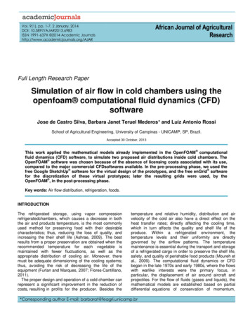
Silva et al.5Figure 9. Air ductwork distribution showing air flowpatternsFigure 6. Proposed air distribution using a ductwork.velocity of the section (ms -1), and A is the sectional area (m²).Proposal #2In this second proposal, we placed an evaporator, commerciallyknown as cassette, in the center of the cold room (Figures 7 and 8).Currently, this evaporator is used exclusively in air conditioners; it issquare-shaped with four air outlets, and a volumetric flow of 1800m³h-1.RESULTS AND DISCUSSIONFigure 7. Ilustration of the cassette evaporatorplaced at the center of the cold chamber.In the first simulationanairflow pipeline networkconnected to the original evaporator of the refrigeratorwas used, but it was not a satisfactory alternative toreduce the temperature differential. The simulationshowed that the temperature differential ( T) had a valueof approximately 16 C higher than the differential ( T) of14 C with the same evaporator without ductwork (Figures9, 10 and 11). The temperature differential ( T) used inthis analysis is the difference between the value of thelowest temperature and thehighest air inside the coldchamber.In simulation # 2, the cassete evaporator originallydesigned for split system air conditioners, proved to bean alternative to reduce the temperature differential. Inthis problem simulated (Figures 12, 13 and 14), thetemperature differential was worth approximately 7 C,and the same difference found in the work of Ho et al.(2010). It is observed in Figure 12, an ordering of thelines of current, different from Figure 9. Figure 14 showsa larger, more symmetrical filling of the air inside thechamber which differs from that observed in simulationNo. 1 (Figure 11).ConclusionsFigure 8. Cassette evaporator.The OpenFOAM tool proved to be useful in the
6Afr. J. Agric. Res.Figure 10. Distribution of air temperature in the network of ducts.Figure 13. Temperature distribution with the evaporator modelcassete.Figure 11. Distribution of air temperature in the center of the Yplan with a network of ducts .Figure 14. Temperature distribution evaporator model cassetein the center of the Y plan.simulation, and analysis of the studies presented here.The proposed simulated in OpenFOAM using a networkof ducts connected to the original evaporator of therefrigerator, was not a good alternative to reduce thetemperature differences, the maximum differentialtemperature remained at a value higher than that with theoriginal evaporator configuration (no ductwork). Toimprove the circulation of air inside cold rooms andminimize temperature differentials, the simulationOpenFOAM pointed out that the use of cassette modelevaporators and air flow in four directions, currently onlyused in Spilt type air conditioners is an engineeringsolution for reducing temperature differentials inchambers.REFERENCESFigure 12. Temperature distribution and streamlines of theair with the evaporator model cassete.Awbi HB (1989). Application of Computational Fluid Dynamics in RoomVentilation, Build. Enrwon. 24:73-84.
Silva et al.Assis JS (2004). Colheita e pós-colheita da mangueira. Embrapa SemiÁrido Sistemas de Produção.ASHRAE (2009). Fundamental handbook. Atlanta, Georgia, USA:American Society of Heating, Refrigerating and Air ConditioningEngineers.Boulard T, Kittas C, Roy JC, Wang S (2002). Convective and ventilationtransfers in greenhouses, part 2: determination of the distributedgreenhouse climate. Biosyst. Eng. 83:129-147.Chandrasekharan R, Bullard C (2005). Design tool for display caseevaporators. ASHRAE Trans. 111:1071-1082.Cortella G (2002). CFD-aided retail cabinets design. Comput. Electr.Agric. 34:43-66.Cortella G, Manzan M, Comini G (2001). CFD simulation of refrigerateddisplay cabinets. Int. J. Refrig. 24:250-260.D’Agaro P, Cortella G, Croce G (2006). Two and three dimensional CFDapplied to vertical display cabinets simulation. Int. J. Refrig. 29:178190.Djunaedy E, Hensen JLM, Loomans MGLC (2003). Development of aguideline for selecting a simulation tool for airflow prediction. EighthInternational IBPSA Conference. pp. 267-274.Flores-Cantillano RF (2011). A cadeia do frio e a qualidade das frutas ehortaliças.Disponívelem: http://www.infobibos.com/Artigos/2011 1/CadeiaFrio/index.htm .Acesso em: 14 set 2011.Furlan EF, Marques D (2007). Refrigeração x Energia elétrica.Frigorífico 139:30-35.Fukuyo K (2004). Simulations of Task-Ambient Air-ConditioningSystems by Computational Fluid Dynamics, Refrigerating-CycleSimulator, and Pedestrian-Behavior Model. Int. Refrig. Air Cond.Conf. P. 729.Fortuna AO (2000). Técnicas computacionais para dinâmica dosfluidos: Conceitos básicos e aplicações. São Paulo: Edusp.Gan G (1995). Evaluation of room air distribution systems usingcomputational fluid dynamics. Ener. Build. pp. 83-93.Gaspar PD, Gonçalves LCC, Pitarma RA (2012). Detailed CFDmodelling of open refrigerated display cabinets. Hindawi PublishingCorporation - Modelling and Simulation in Engineering.Gaspar PD, Miranda A, Pitarma RA (2003). Estudo comparativo dedesempenho de códigos de DFC na modelação de equipamentos derefrigeração abertos. Universidade de Évora - VII Congresso deMecânica Aplicada e Computacional.Gaspar PD, Pitarma RA (2005). Estudo numérico do desempenhotérmico de expositores refrigerados abertos. Rev. Iberoam. Ing.Mecánica 9:21-30.Gebremedhin KG, Wu B (2005). Simulation of flow field of a ventilatedand occupied animal space with different inlet and outlet conditions.J. Thermal. Biol. 30:343-353.Ho SH, Rosario L, Rahman M (2010). Numerical simulation oftemperature and velocity in a refrigerated warehouse. Int. J. Refrig.33:1015-1025.Hoang ML, Verboven P, Baerdemaeker J, Nicoli BM (2000). Analysis ofthe air flow in a cold store by means of computational fluid dynamics.Int. J. Refrig. 23:127-140.Jian Y, Li D, Xu H, Ma X (2006). Analysis of cold air distribution systemin an office building by the numerical simulation method. SixthICEBO-International Conference for Enhanced Building Operations.Krause E (1985). Computational fluid dynamics: Its presente status andfuture direction. Computers. Fluids, 13:239-269.Launder BE, Spalding DB (1974). The numerical computation ofturbulent flows. Comput. Methods Appl. Mech. Eng. pp. 269–2897Luo S, Roux B (2004). Modeling of the HESCO nozzle diffuser used inIEA Annex-20 experiment test room. Build. Environ. pp. 367-384.Lu YL, Zhang WH, Gong Y, Tao WQ (2007). Numerical Simulation ofRefrigerated Display Cabinets. BIC-TA (Bio-Inspired Computing:Theories and Applications) Second International Conference. pp.258-262.Moureh J, Tapsoba S, Derens E, Flick D (2009). Air velocitycharacteristics within vented pallets loaded in a refrigerated vehiclewith and without air ducts. Int. J. Refrig. 32:220-234.Nahor HB, Hoang ML, Verboven P, Baelmans M, Nicolai BM (2005).CFD model of the airflow, heat and mass transfer in cool stores. Int.J. Refrig. 28:368-380.Nielsen PV (2004). Computational fluid dynamics and room airmovement. Int. J. Indoor Environ. Health 14:134-143.Norton T, Sun DW, Grant J, Fallon R, Dodd V (2007). Applications ofcomputational fluid dynamics (CFD) in the modelling and design ofventilation systems in the agricultural industry: A review. Bioresour.Technol. 98:2386-2414.Rodi W (1980). Turbulence models and their application in hydraulics –A state of the art review. International Association for HydroEnvironment Engineering and Research.Souza Z (2011). Projeto de Máquinas de Fluxo. 1ed. Rio de Janeiro,Editora Interciência.Spoolder HAM, Edwards SA, Armsby AW, Corning S (2000). A withinfarm comparison of three different housing systems for finishing pigs.Proceedings of the First International Conference on Swine Housing,Des Moines, Iowa, pp. 40-48.Tassou SA, Xiang W (1998). Modellingthe environment within a wetair-cooled vegetable store. J. Food Eng. 38:169-187.Xie J, Qu X, Shi J, Sun DW (2006). Effects of design parameters onflow and temperature fields of a cold store by CFD simulation. J.Food Eng. 77:355-363.Yan-Li LV, Wen-Hui Z, Yi G, Wen-Quan T (2007). Numerical simulationof refrigerated display cabinets. Bio-Inspired Computing: Theoriesand Applications. Second International Conference.Zhao B, Li X, Yan Q (2003). Simplified method for indoor airflowsimulation. Build. Environ. 38:543-552.
In the pre-processing step, we used the free Google SketchUp software for the virtual design of the prototypes, and the free enGrid software (Figure 2) for the discretization of these virtual prototypes and to generate the grids; later the resulting grids were used in the post-processing phase by the OpenFOAM (Figure 3).