Transcription
nRF5 Series: Developing withSEGGER Embedded StudioGetting Started Guidev1.31159720 163 v1.3 / 2019-09-16
ContentsRevision history. . . . . . . . . . . . . . . . . . . . . . . . . . . . . . . . . .iii1Introduction.42Minimum requirements. . . . . . . . . . . . . . . . . . . . . . . . . . .53Related documentation. . . . . . . . . . . . . . . . . . . . . . . . . . . .64Development kits, boards, and chips.5SoftDevices.6Running a first test.7Setting up your toolchain.89. . . . . . . . . . . . . . . . . . . . . . . . . . . . . . . . . . . . . . . . . . . . . . . . . . . . .7. . . . . . . . . . . . . . . . . . . . . . . . . . . . . . . . . .8. . . . . . . . . . . . . . . . . . . . . . . . . . . . . . . . . . . . . . . . . . . . . . . . . . . . . . .9107.1 Nordic tools and downloads . . . . . . . . . . . . . . . . . . . . . . . . . . .7.2 Setting up the nRF5 SDK . . . . . . . . . . . . . . . . . . . . . . . . . . . . .7.3 Installing SEGGER tools . . . . . . . . . . . . . . . . . . . . . . . . . . . . . .7.4 Installing the nRF5x Command Line Tools . . . . . . . . . . . . . . . . . . . . . .10131314Programming an application.15. . . . . . . . . . . . . . . . . . . . . . . .8.1 Erasing the board . . . . . . . . . . . . . . . . . . . . . . . . . . . . . . . .8.2 Importing Keil projects . . . . . . . . . . . . . . . . . . . . . . . . . . . . . .8.3 Compiling the application . . . . . . . . . . . . . . . . . . . . . . . . . . . .8.4 Configuring placement of the SoftDevice . . . . . . . . . . . . . . . . . . . . . .8.5 Programming the firmware . . . . . . . . . . . . . . . . . . . . . . . . . . . .8.6 Adding files . . . . . . . . . . . . . . . . . . . . . . . . . . . . . . . . . .8.6.1 Adding source files . . . . . . . . . . . . . . . . . . . . . . . . . . . . .8.6.2 Including header files . . . . . . . . . . . . . . . . . . . . . . . . . . . .1516212225252526Communicating with the board.28. . . . . . . . . . . . . . . . . . . . . .9.1 Connecting via RTT . . . . . . . . . . . . . . . . . . . . . . . . . . . . . . .9.1.1 Connecting via RTT on Windows . . . . . . . . . . . . . . . . . . . . . . . .9.1.2 Connecting via RTT on Linux . . . . . . . . . . . . . . . . . . . . . . . . . .9.2 Connecting via CDC-UART . . . . . . . . . . . . . . . . . . . . . . . . . . . .10 Testing the application. . . . . . . . . . . . . . . . . . . . . . . . . . .282829293110.1 Testing with a mobile device . . . . . . . . . . . . . . . . . . . . . . . . . . . 3110.2 Testing with a computer . . . . . . . . . . . . . . . . . . . . . . . . . . . .3211 Debugging. . . . . . . . . . . . . . . . . . . . . . . . . . . . . . . . . .34Glossary . . . . . . . . . . . . . . . . . . . . . . . . . . . . . . . . . . . . . 35Acronyms and abbreviations. . . . . . . . . . . . . . . . . . . . . . . . . . . . 36Legal notices. . . . . . . . . . . . . . . . . . . . . . . . . . . . . . . . . . .1159720 163 v1.3ii37
Revision historyDateVersionDescriptionSeptember 2019 1.3Fixed broken linksJanuary 20191.2Updated Importing Keil projects on page 16October 20181.1Added Adding files on page 25July 20181.0First release1159720 163 v1.3iii
1IntroductionThis guide will help you get started with your nRF5 Series DK (Development Kit) and developing yourapplication with SEGGER Embedded Studio (SES).If you have worked with any of Nordic Semiconductor's products before, you are probably familiar withthe required software tools. In this case, this guide will mostly provide reference information.If this is your first time developing software for a Nordic Semiconductor System on Chip (SoC), this guidewill help you set up your development toolchain and guide you through all the steps that are necessary todevelop, program, test, and debug your application.This guide describes how to work with SES. SES is a cross-platform Integrated Development Environment(IDE), so you can run it on different operating systems. For use with Nordic Semiconductor devices, youcan get a free license that has no limitations.There are two Getting Started Guides that show how to work with different IDEs: nRF5 Series: Developing with SEGGER Embedded Studio (this document) nRF5 Series: Developing on Windows with ARM Keil MDKCheck out the Nordic DevZone for additional setup information and help.1159720 163 v1.34
2Minimum requirementsEnsure that you have all the required hardware and that your computer fulfills the software requirements.Hardware requirements One of the following nRF5 Series development kits: nRF52840 DK nRF52 DK nRF51 DKMicro-USB 2.0 cablePersonal computer (PC) or MacSmartphone or tablet that supports Bluetooth Low EnergyOptional: nRF52840 Dongle or nRF51 DongleSoftware requirementsOne of the following operating systems: Windows 7, Windows 8, or Windows 10 macOS Linux1159720 163 v1.35
3Related documentationThis guide is a starting point and gives essential information for getting started with software developmenton nRF5 Series devices. For more detailed information, check the documentation of the separatecomponents and tools.Development Kit User GuidesnRF52840 Development KitnRF52 Development KitnRF51 Development KitDongle User GuidesnRF52840 DonglenRF51 DongleCompatibility MatricesnRF52840 Compatibility MatrixnRF52832 Compatibility MatrixnRF52810 Compatibility MatrixnRF51 Series Compatibility MatrixnRF5 SDK documentationnRF5 SDK v15.3.0Tools User GuidesnRF Command Line ToolsnRF Connect Bluetooth Low Energy1159720 163 v1.36
4Development kits, boards, and chipsEach nRF5 Series DK contains a board, which in turn contains a chip. Some of Nordic Semiconductor's toolstarget the chip, while others target the development board or the development kit. Therefore, you mustbe aware of the relation between the different components.You can find all compatibility information in the compatibility matrix for each chip. The following tablesummarizes the information that you must be aware of for programming your development board.Development kitDevelopment boardChipnRF52840 DKPCA10056nRF52840nRF52840 DonglePCA10059nRF52840nRF52 DKPCA10040nRF52832/nRF52810nRF51 DKPCA10028nRF51422nRF51 DonglePCA10032nRF51422Table 1: Relation between development kits, boards, and chips1159720 163 v1.37
5SoftDevicesA SoftDevice is a wireless protocol stack that complements an nRF5 Series SoC. Nordic Semiconductorprovides them as qualified, precompiled binary files. While it is possible to build applications withoutusing a SoftDevice, all nRF5 SDK example applications that use Bluetooth Low Energy or ANT require aSoftDevice.See the compatibility matrices for detailed information about which SoftDevice versions are supported foreach chip. The following table summarizes the usage scenarios for each SoftDevice.ProtocolRoleChipSoftDeviceBluetooth Low EnergyPeripheral nRF51422 nRF51822S110 nRF52810 nRF52832S112Central or Peripheral nRF51422 nRF51822S120Central and Peripheral nRF51422 nRF51822S130 nRF52832S132 nRF52840S140 nRF51422S210 nRF52832S212Peripheral nRF51422S310Central and Peripheral nRF52832S332ANTBluetooth Low Energy and ANTTable 2: SoftDevice overview1159720 163 v1.38
6Running a first testBefore you start developing, program and run a simple application on your development board toensure that the board functions as expected and the communication between your computer and yourdevelopment board works.Before you begin, download the latest compatible version of the nRF5 SDK. For information about whichSDK supports which IC revisions, check the compatibility matrices.The nRF5 SDK contains precompiled HEX files of the most common examples. Extract the zip file into afolder of your choosing.1. Power up the nRF5 Series development board:a) Connect one end of a micro-USB 2.0 cable to the USB connector on the board and the other end toone of your PC's USB host ports.b) Slide the power switch to "ON".Observe that LED1 starts blinking.2. Open a file explorer and confirm that the development board has appeared as a removable drivenamed "JLINK".3. In the folder where you extracted the nRF5 SDK, navigate to examples\peripheral\blinky\hex.4. Select the HEX file that corresponds to your development board and copy it to the JLINK drive.The development board will now restart and run the application.If the LEDs on the board start blinking, you have successfully programmed your first application! Next,continue to set up your development toolchain and program a more advanced application.1159720 163 v1.39
7Setting up your toolchainBefore you can start developing, you must install the required software. This software includes toolsto connect to your development board, an IDE for developing your application, and the nRF5 SDK thatprovides libraries and example applications.See Nordic tools and downloads on page 10 for an overview of available tools and the links todownload the latest versions for your operating system.The following tools are required: nRF5 SDK SEGGER Embedded Studio (SES) SEGGER J-Link Software and Documentation PackThe following tools are optional: nRF5x Command Line Tools for Windows, Linux32, Linux64, or macOS (all including nrfjprog)See the following sections for installation instructions.7.1 Nordic tools and downloadsThis overview lists all available Nordic Semiconductor tools and supported IDEs. Not all of these tools arerequired. To help you pick the IDE and tools you want to use, see the following sections for common setupscenarios.Development IDEPick one of the IDEs with a compiler supported by Nordic:IDEWindowsLinuxOSXSEGGER EmbeddedStudio (SES)YesYesYesMDK-ARM Keil µVisionYesNoNoGNU/GCCYesYesYesIARYesNoNoSES is the recommended platform. It is free for use with nRF devices.Essential toolsYou need to download these Nordic tools to develop with our devices.1159720 163 v1.310
Setting up your mples, sourceDevelopment files, SoftDevicesKit)nRFCommandLine ToolsCollection ofcommand linetools, like ows/LinuxnRF5 SDK v15.3.0BLE/ANTnRF5 SDK for Meshv3.2.0BluetoothMeshnRF5 SDK for Threadand Zigbee v3.1.0Thread andZigbeenRF Command LineToolsBLE/ANTnRF Command Line ToolsOptional toolsThese tools are not essential, but we recommend that you use them.1159720 163 v1.311
Setting up your colSoftDeviceWireless protocolstackClick the Downloadtab on:nRF51 SoftDeviceSpecificationsBLE/ANTnRF52840 ProductpagenRF52 SoftDeviceSpecificationsnRF52832 ProductpagenRF52810 ProductpagenRF51822 ProductpagenRF51422 ProductpagenRF Connect forDesktopExpandable desktopnRF Connect for OS-Xtool with several apps,nRF Connect forincluding:Ubuntu Linux Peer devicenRF Connect foremulatorWindows Power ProfilernRF ConnectBLEBluetooth Low Energy Programmer Cloud GatewaynRF Connect forMobilePeer device emulatorapp for smartphonesAndroid v4.3 or laterNordic nRF ToolboxappApp that contains allthe Nordic appsAndroid v4.3 or laterBLEIOS v8 or laterBLEIOS v8 or laterWindows Phone v8.1or laternRF pynrfjprogSimple Pythoninterface for thenrfjprog DLLANTware IIPeer device emulator ANTware IIfor the ANT protocolrunning on computersnRF SnifferApp for monitoring on- nRF Sniffer downloadair trafficnRF Thread Topology Tool for visualizingMonitorThread mesh networktopology in real timenRF pynrfjprognRF Thread TopologyMonitor for UbuntuLinux 64-bitnRF5x pynrfjprogBLE/ANTANTnRF SnifferBLEnRF Thread TopologyMonitorThreadnRF Thread TopologyMonitor for WindowsThread BorderRouter1159720 163 v1.3Gateway forconnecting ThreadThread Border Router12Thread Border Router Thread
Setting up your colnetwork to theInternetSee also Nordic mobile apps for a list of available Bluetooth Low Energy and Mesh mobile apps for iOS,Android, and Windows Phones.7.2 Setting up the nRF5 SDKThe nRF5 SDK does not require installation. You only need to download and extract the files.If you followed the instructions in Running a first test on page 9, you already downloaded and extractedthe nRF5 SDK files and are all set up.To set up your SDK environment:1. Download the nRF5 SDK zip file.If you have an nRF52 device, select the latest version. For nRF51 devices, select the latest version withsupport for nRF51 (currently, v12.3.0). For information about which SDK supports which IC revisions,check the compatibility matrices.2. Extract the zip file to the directory that you want to use to work with the SDK.This folder will be referred to as SDK dir in the following documentation.Note: Compilers tend to run into problems with long path names. Therefore, place the folder asclose to the root level of your file system as possible (for example, at C:/Nordic/SDK). Also,avoid using spaces in the file path and folder name.7.3 Installing SEGGER toolsDownload and install the most recent releases of SES and the J-Link Software and Documentation Pack.1. Download the software packages for your operating system from SEGGER downloads.You need the following packages: Embedded Studio for ARM (version 3.30 or later) J-Link Software and Documentation Pack (version 6.10g or later)2. Install both packages.3. Obtain and activate your free license for SES:a) Open SES.SES will automatically load a test project.b) Click Build Build and Debug.A window asking for a license will pop up. SES is free of charge for use with Nordic Semiconductordevices, but you still need to request and activate a license.c) Select Activate Your Free License and fill in your information to request a license.Note: In SES versions before 3.34, this option was called Get a Free License.The license is sent to you in an email.d) After you receive your license key, enter it to activate the license.1159720 163 v1.313
Setting up your toolchain7.4 Installing the nRF5x Command Line ToolsThe nRF5x Command Line Tools are used for developing, programming, and debugging of NordicSemiconductor's nRF5x SoCs (System on Chip).When installing on macOS or Linux, the SEGGER software must be installed in its default location, or theshared library must be placed so that dlopen() can find it. The default location is: On macOS: /Applications/SEGGER/JLink On Linux: /opt/SEGGER/JLinkThe SEGGER software can be installed by downloading and running the installer from SEGGER Software.When installing the nRF5x Command Line Tools on Windows, SEGGER software is automatically installed inaddition to the tools.Complete the following steps to install the nRF5x Command Line Tools:1. Download the software for your operating system: Windows: nRF5x-Command-Line-Tools for Win32Linux 32-bit: nRF5x-Command-Line-Tools-Linux-i386Linux 64-bit: nRF5x-Command-Line-Tools-Linux-x86 64macOS: nRF5x-Command-Line-Tools for Os X2. Install the software by running the installer and following the given instructions, or by extracting the.tar archive anywhere on your file system and adding the extracted folders to your path.3. Enter the following command in a command line to make sure that nrfjprog is installed correctly:nrfjprog --versionIf you get an error message that the command cannot be found, nrfjprog must be manually added tothe PATH. On Windows:a) Go to the Windows Advanced system settings and click Environment Variables.b) Select the Path variable and click Edit.c) Add the following text at the end of the variable value: ;C:\Program Files (x86)\NordicSemiconductor\nrf5x\binMake sure that you add a semicolon (;) between entries in the PATH values: path1;path2d) Click OK twice.On Linux, assuming that you have extracted the .tar archive into /opt/nrfjprog:a) Add the following command to the configuration file for your command line, for example, to /.bashrc:export PATH PATH:/opt/nrfjprogOpen a new command prompt and repeat the command. It should now succeed.1159720 163 v1.314
8Programming an applicationAfter setting up the required toolchain, you are ready to compile your application and program (or "flash")it to your development board.Starting with v14.1.0, the nRF5 SDK supplies SEGGER Embedded Studio projects. If you are using an olderversion of the nRF5 SDK (for example, nRF5 SDK v12.3.0, which supports nRF51 Series devices), you mustimport and convert the Keil µVision projects.There is a series of video tutorials that show how to get started with SEGGER Embedded Studio incombination with the nRF5 SDK. Check them out here: Getting started with SEGGER Embedded Studio andthe nRF5 SDK8.1 Erasing the boardBefore you program an example to the development board, you should erase the contents of the board.There are different ways to erase the board. You can, for example, use SES or the command line toolnrfjprog (part of the nRF5x Command Line Tools). To erase the contents of the board with SES, complete the following steps:a) Select Target Connect J-Link.b) After the connection is established, select Target Erase All. To erase the contents of the board with nrfjprog, enter the following command:1159720 163 v1.315
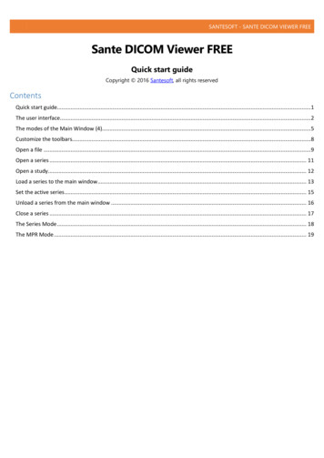
Programming an application For nRF51 devices: nrfjprog --family nRF51 --eraseall For nRF52 devices: nrfjprog --family nRF52 --eraseall8.2 Importing Keil projectsIf you are using a version of the SDK that supports SES, thus nRF5 SDK v14.1.0 or later, you should openone of the supplied SES projects and skip this step. If you are using an older version of the SDK, forexample, nRF5 SDK v12.3.0 for nRF51 Series devices, you must create your own SES projects based on thesupplied Keil projects.Before you begin, install the CMSIS-CORE Support Package. To do so, open SES, go to Tools PackageManager, and select and install CMSIS-CORE Support Package.Figure 1: SES Package ManagerComplete the following steps to import a Keil project into SES:1. Select File Import Project Import Keil MDK Project.In SES versions before 3.40, this option was located under File Import IAR EWARM / Keil MDKProject.2. Navigate to the folder that contains the nRF5 SDK and select the example that you want to import.Use the *.uvprojx file that is located in the arm5 no packs folder.3. In the Import Build Configuration window that appears, select Internal Toolchain.1159720 163 v1.316
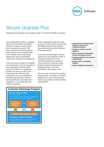
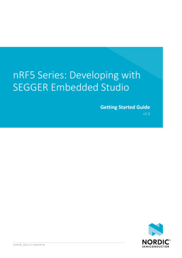
Programming an application4. If the project that you imported contains a Target for flashing the SoftDevice, delete this Target in SES:a) Select Project Build Configurations.b) Under Public Configurations, select the Target (for example, flash s130 nrf51 2.0.1 softdevice).c) Click the - symbol to remove the Target.The build configuration should now look similar to this:5. Add the nRF5 MDK files that are required for startup and system setup.In Keil µVision, these files are provided by the nRF DeviceFamilyPack. Since this pack is not availablefor SES, you must add them manually to the SES project.a) Download ses nrf51 startup.s and ses nrf52 startup.s and save them in a new folder SDK dir/components/toolchain/embedded studio.b) In the Project Explorer, navigate to Internal Files and remove the Cortex M Startup.s file.c) Right-click Internal Files and select Add Existing File.d) Browse to the SDK dir/components/toolchain/ folder and select the .c file thatcorresponds to your device (for example, system nrf52.c).e) Right-click Internal Files and select Add Existing File again. This time, select the startup file thatyou downloaded, for example, SDK dir/components/toolchain/embedded studio/ses nrf51 startup.s.1159720 163 v1.317
Programming an applicationThe Project Explorer should now look similar to this:6. Include the device header files in the project:a) Right-click your project and select Edit Options.b) Select Preprocessor.c) Add the following path to the User Include Directories field: ././././././components/deviceThe user include directories should now look similar to this:1159720 163 v1.318
Programming an application7. If your project uses modules that require section variables (for example, the Peer Manager, Flash DataStorage, or Flash Storage), define where in the flash information from these modules should be stored.a) Download the flash placement.xml and place it in your project directory.Files are provided for the following versions of the nRF5 SDK: For nRF5 SDK v12.x.x: flash placement.xml For nRF5 SDK v13.x.x and nRF5 SDK v14.0.0: flash placement.xmlb) If you are using SES v3.50 or later, right-click your project, select Edit Options, select Linker, andchange the Linker option to GNU.1159720 163 v1.319
Programming an applicationNote: This option does not exist in SES versions before 3.50.c) Right-click on your project in the Project Explorer and select Import Section Placement.1159720 163 v1.320
Programming an applicationd) Confirm that you want to use the section placement for the current build configuration.8.3 Compiling the applicationYou can compile the application from a SES project provided by the nRF5 SDK v14.2.0 or later, or from theproject that you created based on an older SDK example.1. Open your project in SES.In nRF5 SDK v14.2.0 or later, SES projects are located in the ses subfolder of the example folder, forexample, SDK dir/examples/ble peripheral/ble app uart/pca10040/s132/ses.2. Select Build Build project target.Alternatively, press F7. Make sure that there are no build errors.The output should look similar to this:1159720 163 v1.321
Programming an application8.4 Configuring placement of the SoftDeviceIf your application uses Bluetooth or ANT, you must program a SoftDevice in addition to the application.Note:If your application does not use a SoftDevice, you can skip this step.If you are using a SES project from nRF5 SDK v14.2.0 or later, the placement of the SoftDevice isalready configured correctly and you can skip this step.If your application requires a SoftDevice, the flash and SRAM position where the compiled binary will beplaced must be configured as follows:1. In SES, right-click your project and select Edit Options.2. Select Linker.3. In the Section Placement Macros field, add values for FLASH START and SRAM START.To find the correct values, check the Keil project that you imported (in Keil µVision, select Options forTarget Target), or program the firmware with approximate values, run it, and check the log output inthe debug terminal for the recommended values.For example, when running the ble app uart example application from nRF5 SDK v12.3.0 on PCA10028with SoftDevice S130 v2.0.1, specify the section placement macros as shown:1159720 163 v1.322
Programming an application4. Select Build Rebuild project target to rebuild the project.Alternatively, press ALT F7.The output should now look similar to this, with space reserved for the SoftDevice:5. Right-click your project and select Edit Options.6. Select Preprocessor.7. Add the definition NO VTOR CONFIG to the Preprocessor Definitions.This definition tells SES to expect a SoftDevice to be present that will forward exceptions and interruptsto the application.1159720 163 v1.323
Programming an application8. In the Debug section of the project options, select Loader.9. Add the absolute path to the SoftDevice to the Additional Load File[0] field, forexample, ././././././components/softdevice/s130/hex/s130 nrf51 2.0.1 softdevice.hex.1159720 163 v1.324
Programming an application8.5 Programming the firmwareAfter compiling the application, you can program it to the development board. If you configured aSoftDevice to be used, it is programmed together with the application.1. Connect the development board to your computer.2. Select Debug Build and Run.Alternatively, press Ctrl F5.8.6 Adding filesAfter compiling and programming an unmodified example to ensure that your toolchain is set up correctly,modify your project by adding files and libraries.8.6.1 Adding source filesAll source files that are part of the application you are developing must be added to the project.You can add existing files or create files in the project directory. To add an existing file, right-click your project or any subfolder in the Project Explorer and select AddExisting File. Browse to the file that you want to import and open it.The original file is not copied into the project, but it is included from its original location. That meansthat any modifications that you do will apply to all projects that use this file.1159720 163 v1.325
Programming an application To create a file, right-click your project or any subfolder in the Project Explorer and select Add NewFile.By default, the file is created in the project directory.8.6.2 Including header filesRequired header files must be linked to your project by adding their path to the user include directories.Header files contain function declarations and macro definitions. You can request the use of header filesby adding a #include preprocessing directive in your source files.Header files are not linked to the project through the Project Explorer. To include a header file so that SEScan find it, you must add its path to the list of directories in which SES looks for header files:1. In the Project Explorer, right-click your project and select Edit Options.2. In the Project Options window, select the Common configuration (sorted under PrivateConfigurations).3. Select Preprocessor.4. Double-click User Include Directories and add the path to the folder that contains the header file.You can specify an absolute path or a path that is relative to the project directory. Using a relative pathis preferable if you might want to move or copy your project to, for example, a new SDK version in thefuture.1159720 163 v1.326
Programming an application5. Click OK.1159720 163 v1.327
9Communicating with the boardUnless you programmed a very simple application, you probably want to connect to the board from yourcomputer to display logging information or send input. You can use Real Time Transfer (RTT) or UniversalAsynchronous Receiver/Transmitter (UART) for communicating with the board.SEGGER Real Time Transfer (RTT) is a proprietary technology for bidirectional communication thatsupports J-Link devices and ARM-based microcontrollers. The advantage of using RTT is that it is veryefficient and does not require any other peripheral than the J-Link debugging interface. RTT is directlysupported in SES.Connecting via UART is quick and power-efficient, but it requires dedicated use of the UART peripheral forlogging. The nRF5 DKs and the nRF51 Dongle include a UART to USB CDC ACM bridge, which is needed toconnect to the UART. Alternatively, you can use an external UART to USB bridge. We use the term CDCUART to refer to UART communication through the UART to USB CDC ACM bridge, to distinguish it fromcommunication through the Nordic UART Service (NUS) over Bluetooth Low Energy.9.1 Connecting via RTTSES directly supports RTT. You can see RTT output in the Debug Terminal during debugging sessions.Alternatively, you can use J-Link RTT to view RTT output. See the following sections for instructions forWindows and Linux.9.1.1 Connecting via RTT on WindowsTo communicate via RTT, connect your development board via USB and run the J-Link RTT Viewer.Note: SES natively supports RTT. If enabled, the monitor shows up when you start debugging.Alternatively, you can use SEGGER's J-Link RTT Viewer as described below.The J-Link RTT Viewer is installed as part of the nRF5x Command Line Tools.To run the J-Link RTT Viewer on Windows, complete the following steps:1. Select the correct target device.The target device is represented by the ID of your development board.2. Select SWD as the target interface.1159720 163 v1.328
Communicating with the board9.1.2 Connecting via RTT on LinuxTo communicate via RTT, connect your development board via USB and use SEGGER's J-Link RTT toestablish a connection.Note: SES natively supports RTT. If enabled, the monitor shows up when you start debugging.Alternatively, you can use SEGGER's J-Link RTT Viewer as described below.SEGGER's J-Link RTT is part of the J-Link Software and Documentation Pack, which is available fromSEGGER downloads.To use J-Link RTT on Linux, complete the following steps:1. Enter JLinkExe -if SWD to set up the connection:you@yourcomputer: JLinkExe -if SWDSEGGER J-Link Commander V5.10u (Compiled Mar 17 2016 19:06:22)DLL version V5.10u, compiled Mar 17 2016 19:06:19Connecting to J-Link via USB.O.K.Firmware: J-Link OB-SAM3U128-V2-NordicSemi compiled Mar 15 2016 18:03:17Hardware version: V1.00VTref 3.300VType "connect" to establish a target connection, '?' for helpJ-Link 2. Enter connect at the prompt to establish the connection.JLinkExe will ask for additional information. You can accept the default values.3. From another terminal, start JLinkRTTClient.RTT output is visible in the terminal that runs JLinkRTTClient.9.2 Connecting via CDC-UARTTo connect via CDC-UART, start a terminal emulator and connect to the used COM port.There is a wide variety of terminal emulators that you can use, for example, minicom or screen (bothterminal-based, available for Linux), Termite (GUI-based, Windows only), or PuTTY (GUI-based, availablefor multiple operating systems).When configuring the connection, use the following UART settings: Baud rate: 115.2008 data bits1 stop bitNo parityHW flow control: RTS/CTSThe following instructions show how to configure Termite correctly. Other terminal emulators can be setup in a similar way.1. Download and install the latest version of Termite.2. Connect the development board to your computer.3. Open Termite and click Settings.Depending on what devices you have connected to your computer, you might have several choices, asshown in the following figure:1159720 163 v1.329
Communicating with the board4. Select the correct COM port to connect to the board.To find the correct port, follow these steps:a)b)c)d)Go to the start menu in Windows and type devmgmt.msc to open the Device Manager.Scroll down and expand Ports (COM & LPT).Find the port named JL
4.Select the HEX file that corresponds to your development board and copy it to the JLINK drive. The development board will now restart and run the application. If the LEDs on the board start blinking, you have successfully programmed your first application! Next, continue to set up your development toolchain and program a more advanced .