Transcription
The Bose Lifestyle 12 SystemOwner’s GuideDecember 20, 2001AM191409 01 V.pdf
Safety InformationWARNING: To reduce the risk of fire or electric shock, do not expose the system to rain ormoisture.CAUTIONRISK OF ELECTRICAL SHOCKDO NOT OPENCAUTION: TO REDUCE THE RISK OF ELECTRIC SHOCK,DO NOT REMOVE COVER (OR BACK).NO USER-SERVICEABLE PARTS INSIDE.REFER SERVICING TO QUALIFIED PERSONNEL.These CAUTION marks are located on the back panel and bottom of your Lifestyle musiccenter and the bottom panel of your Acoustimass module:The lightning flash with arrowhead symbol, within an equilateral triangle, is intended to alertthe user to the presence of uninsulated dangerous voltage within the system enclosure thatmay be of sufficient magnitude to constitute a risk of electric shock.The exclamation point within an equilateral triangle, as marked on the system, is intended toalert the user to the presence of important operating and maintenance instructions in thisowner’s guide.CAUTION: To prevent electric shock, match wide blade of plug to wide slot, insert fully.Class 1 laser productCLASS 1KLASSE 1LUOKAN 1KLASS s compact disc player is classified as a CLASS 1 LASER product. TheCLASS 1 LASER PRODUCT label is located on the bottomof the unit.CAUTION: Use of controls or adjustments or performance of procedures other than thosespecified herein may result in hazardous radiation exposure. The compact disc player shouldnot be adjusted or repaired by anyone except properly qualified service personnel.Class B emissions limitsThis Class B digital apparatus meets all requirements of the Canadian Interference-CausingEquipment Regulations.BatteriesPlease dispose of used batteries properly, following any local regulations. Do not incinerate.Additional safety informationSee the additional instructions on the Important Safety Information page enclosed with thisowner’s guide.Please read this owner’s guidePlease take the time to follow this owner’s guide carefully. It will help you set up and operateyour system properly, and enjoy all of its advanced features. Save your owner’s guide forfuture reference.2December 20, 2001AM191409 01 V.pdf
Important Safety Instructions1. Read these instructions – for all componentsbefore using this product.2. Keep these instructions – for future reference.3. Heed all warnings – on the product and in theowner’s guide.4. Follow all instructions.5. Do not use this apparatus near water ormoisture – Do not use this product near abathtub, washbowl, kitchen sink, laundry tub, in awet basement, near a swimming pool, or anywhere else that water or moisture are present.6. Clean only with a dry cloth – and as directedby Bose Corporation. Unplug this product fromthe wall outlet before cleaning.7. Do not block any ventilation openings.Install in accordance with themanufacturer’s instructions – To ensurereliable operation of the product and to protect itfrom overheating, put the product in a positionand location that will not interfere with its properventilation. For example, do not place the producton a bed, sofa, or similar surface that may blockthe ventilation openings. Do not put it in a built-insystem, such as a bookcase or a cabinet that maykeep air from flowing through its ventilationopenings.8. Do not install near any heat sources, suchas radiators, heat registers, stoves or otherapparatus (including amplifiers) that produce heat.9. Do not defeat the safety purpose of thepolarized or grounding-type plug. A polarized plug has two blades with one widerthan the other. A grounding-type plug hastwo blades and a third grounding prong. Thewider blade or third prong are provided foryour safety. If the provided plug does not fitin your outlet, consult an electrician forreplacement of the obsolete outlet.10. Protect the power cord from being walkedon or pinched, particularly at plugs, convenience receptacles, and the point wherethey exit from the apparatus.11. Only use attachments/accessories specified by the manufacturer.12. Use only with the cart, stand, tripod,bracket or table specified by themanufacturer or sold with theapparatus. When a cart is used,use caution when moving thecart/apparatus combination toavoid injury from tip-over.13. Unplug this apparatus during lightningstorms or when unused for long periods oftime – to prevent damage to this product.AM191409 01 V.pdf14. Refer all servicing to qualified service personnel. Servicing is required when the apparatushas been damaged in any way: such as powersupply cord or plug is damaged; liquid hasbeen spilled or objects have fallen into theapparatus; the apparatus has been exposed torain or moisture, does not operate normally, orhas been dropped – Do not attempt to service thisproduct yourself. Opening or removing covers mayexpose you to dangerous voltages or other hazards.Please call Bose to be referred to an authorizedservice center near you.15. To prevent risk of fire or electric shock, avoidoverloading wall outlets, extension cords, orintegral convenience receptacles.16. Do not let objects or liquids enter the product –as they may touch dangerous voltage points orshort-out parts that could result in a fire or electricshock.17. See product enclosure for safety relatedmarkings.Information about products thatgenerate electrical noiseIf applicable, this equipment has been tested and foundto comply with the limits for a Class B digital device,pursuant to Part 15 of the FCC rules. These limits aredesigned to provide reasonable protection againstharmful interference in a residential installation. Thisequipment generates, uses, and can radiate radiofrequency energy and, if not installed and used in accordance with the instructions, may cause harmful interference to radio communications. However, this is noguarantee that interference will not occur in a particularinstallation. If this equipment does cause harmful interference to radio or television reception, which can bedetermined by turning the equipment off and on, you areencouraged to try to correct the interference by one ormore of the following measures: Reorient or relocate the receiving antenna. Increase the separation between the equipment andreceiver. Connect the equipment to an outlet on a differentcircuit than the one to which the receiver is connected. Consult the dealer or an experienced radio/TV technician for help.Note: Unauthorized modification of the receiver or radioremote control could void the user’s authority to operatethis equipment.This product complies with the Canadian ICES-003 ClassB specifications.December 20, 2001a
EnglishImportant Safety Instructions18. Use proper power sources – Plug the product intoa proper power source, as described in the operatinginstructions or as marked on the product.19. Avoid power lines – Use extreme care wheninstalling an outside antenna system to keep fromtouching power lines or circuits, as contact withthem may be fatal. Do not install external antennasnear overhead power lines or other electric light orpower circuits, nor where an antenna can fall intosuch circuits or power lines.20. Ground all outdoor antennas – If an externalantenna or cable system is connected to thisproduct, be sure the antenna or cable system isgrounded. This will provide some protection againstvoltage surges and built-up static charges.Section 810 of the National Electrical Code ANSI/NFPA No. 70 provides information with respect toproper grounding of the mast and supportingstructure, grounding of the lead-in wire to an antennadischarge unit, size of grounding conductors,location of antenna-discharge unit, connection togrounding electrodes, and requirements for theground electrode. Refer to the antenna groundingillustration on this page.Antenna groundingExample of antenna grounding as per National ElectricalCode, ANSI/NFPA 70.Antenna lead in wireGround clampAntenna discharge unit(NEC Section 810-20)Grounding conductorsElectric serviceequipment(NEC Section 810-21)Ground clampsPower service groundingelectrode system(NEC ART 250, Part H)Note to CATV system installerThis reminder is provided to call the CATV systeminstaller’s attention to Article 820-40 of the NEC (of USA)that provides guidelines for proper grounding. In particular, it specifies that the cable ground shall be connectedto the grounding system of the building, as close to thepoint of cable entry as is practical.bDecember 20, 2001AM191409 01 V.pdf
ContentsWhere to find Setting UpBefore you begin . 4Unpacking the carton . 5Select the locations for your Lifestyle 12 system . 6Connect the speakers and Lifestyle music center . 9Connecting your home theater components to the Lifestyle 12 system . 12Connect the antennas . 16Attach the wire cover . 16Set up the remote control . 17Set radio channel spacing for dual voltage and 120V systems . 17Turn on the music center . 17Operating Your Lifestyle 12 SystemThe music center display . 18The system controls . 18The music center controls . 19The Lifestyle remote control . 19Listening to your Lifestyle 12 system . 20Listening to video sound . 20Listening to the radio . 21Listening to a CD . 22Using the system with an external component . 22Maintaining Your Lifestyle 12 SystemFine-tuning your system . 23Changing the house code settings . 24Adding speakers . 25Troubleshooting . 26Warranty period . 27Customer service . 27Cleaning the Lifestyle 12 system . 28Product InformationTechnical information . 29Accessories . 29Index . 30Bose Corporation . inside back coverFor your recordsSerial numbers are located on the bottom of the music center and the bottom panel of theAcoustimass module.Music center serial number:Acoustimass module serial number:Dealer name:Dealer phone: Purchase date:We suggest you keep your sales slip and warranty card together with this owner’s guide.AM191409 01 V.pdfDecember 20, 20013
Setting UpBefore you beginThank you for purchasing the Bose Lifestyle 12 system. This complete audio home entertainment system offers superb sound, elegance, technology, and simplicity for music andhome theater.Your system includes: A Lifestyle music center with built-in AM/FM radio and compact disc (CD) player Inputs for a video sound source, an auxiliary source, and a tape deck Powered Acoustimass speakers with a hide-away Acoustimass module An easy-to-use remote controlBose Videostage decoder technology enables the Lifestyle 12 system to reproduce therealism of movie sound especially for a home environment. When a movie soundtrack or CDis produced in a surround sound format, specially encoded sound is sent to any or all of theavailable speakers. Dialogue is usually sent to the front speakers. Sounds from the left orright side of the picture are sent to left or right front speakers. Ambient sounds or specialeffects may be sent to the surround (rear) speakers. Bose Videostage circuitry automaticallydirects the sound to the correct speakers.To select surround-encoded material, look for any of the terms Surround, Dolby Surround,and the double-D symbol* on tapes and discs, and the word “surround”preceding a TV broadcast.When sound is recorded in stereo, but not surround-encoded, Videostage decoder technology directs it to the most appropriate speakers based on the signals received. When viewingolder movies or listening to other monaural programs on your Lifestyle 12 system,Videostage circuitry directs sound so it appears to come from the center of the TV screen.You can listen to any program material in SURROUND (5-speaker) mode, whether theprogram is surround-encoded, stereo, or monaural. You will not hear sound from all fivespeakers all of the time. Even with surround-encoded material there are times when nosounds are directed to the surround speakers. You can select the speaker mode that soundsbest to you for each particular program. * Dolby and the double-D symbol are trademarks of Dolby Laboratories Licensing Corporation.4December 20, 2001AM191409 01 V.pdf
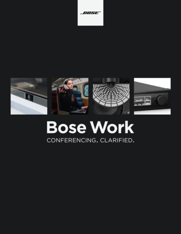
Setting UpUnpacking the cartonCarefully unpack your system. Save all packing materials for possible future use. Theoriginal packing materials provide the safest way to transport your Lifestyle 12 system. Ifany part of the product appears damaged, do not attempt to use the system. Notify Bose or your authorized Bose dealer immediately.Check to be sure your Lifestyle 12 system contains the parts identified in Figure 1.Note: Find the serial numbers on the bottom panel of the Acoustimass module and thebottom of the music center. Then write them on your warranty card and in the spacesprovided on page 3.WARNING: he Acoustimass module weighs 33 pounds (15 kg). Use good lifting practiceto avoid injury.WARNING: To avoid danger of suffocation, keep the plastic bags out of the reach ofchildren.Figure 1What comes with yourLifestyle 12 system: TrebleBassLifestyle music centerAcoustimass module Wire cover AC power pack 5 cubespeaker arraysFM antenna Audio input cableAC power cordSurround speaker cables(orange connectors)Antenna baseAA batteriesAM loop antenna –Lifestyle music centerAC power (mains) pack*Wire coverFM antennaAM loop antennaAM antenna baseRemote control3 AA batteriesAcoustimass module5 cube speaker arraysAC power (mains) cord*Audio input cable5 speaker cables(2 surround and 3 front) 4 self-adhesive rubber feet(for the Acoustimass module) Stereo cable Lifestyle system CD Test CD Front speaker cables(blue connectors)RubberfeetRemote controlStereo cableLifestyle system CDTest CD* Power cord and pack shown above are USA/Canada versions.Dual voltage systems include 1 power cord, 1 adapter, and 2 power packs.The power cords and packs for Europe, UK/Singapore, and Australia are shown below.UK/SingaporeEuropeAM191409 01 V.pdfDecember 20, 2001Australia5
Setting UpSelect the locations for your Lifestyle 12 system When you place your speakers according to the guidelines below, a combination of reflectedand direct sound provides the audio atmosphere of a home theater. You may experiment withthe placement and orientation of the cubes to produce the sound most pleasing to you. Forthe best surround effect, adjust the speakers so you cannot pinpoint where the sound comesfrom. It is preferable not to aim the cubes directly at the listener. For more discussion ofspeaker placement and room acoustics, see “Fine-tuning your system” on page 23.Speaker locationsFollow these guidelines to select locations that provide the maximum home theater effectfrom your Lifestyle 12 system (Figures 2 and 3).CAUTION: Choose a stable and level surface for your speakers. Vibration can cause thespeakers to move, particularly on smooth surfaces like marble, glass, or highly polishedwood. For additional stability, you can add rubber feet to your speakers. You may obtainrubber feet (part no. 178321), free of charge, from Bose . Contact Bose Customer Service(see listings on the inside back cover).Left and right front speakersThe sound from the left and right front speakers should seem to appear at the edge of thepicture, so that the acoustic image is close to the size of the visual image (Figure 2). The frontspeaker cables allow up to 20 feet (6.1 m) distance from the Acoustimass module.1. Place the cubes on line with the horizontal center of the TV screen.2. Place them up to 3 feet (1 m) from the edge of the TV screen.We recommend a maximum distance of 3 feet (1 m) so that the sound does not becometoo separated from the picture. You may wish to vary this distance based on room conditions and personal preference.3. Direct one cube of each array forward. Direct the other cube toward the wall or in adifferent direction to create reflected sound. (See the illustration of reflected sound patterns in Figure 3.)Note: The cube speakers are magnetically shielded so you can place them close to theTV without affecting picture quality.6December 20, 2001AM191409 01 V.pdf
Setting UpCenter speakerThe sound from the center speaker should appear to come directly from the center of thepicture (Figure 2). The center speaker cable allows up to 20 feet (6.1 m) distance from theAcoustimass module.1. Place the speaker on line with the vertical center of the screen, above or below (whichever is closer to the screen), or the closest convenient location.2. Place the speaker in line with the front of the screen (not pushed to the back of the TV).3. Direct each of the cubes slightly away from center, to create a wider area of direct sound(Figure 3).Note: If you put the speakers in a bookcase unit, be sure to place each one at the frontedge of the shelf. Placing speakers in an enclosed space can change the tonal quality of thesound. This effect is minimized if the shelves are filled with books.Figure 2CenterRecommended front speakerlocations Left frontRight front Surround speakersThe surround (rear) speakers create an area of sound around the listener. Place them in theback half of your room. Direct the cubes so that you do not pinpoint the exact location of thesound source (Figure 3). The surround cables allow up to 50 feet (15.2 m) distance from theAcoustimass module.CenterFigure 3Speaker placementAcoustimass 1. Place the speakers at ear height or higher, if possible.2. Direct the cubes to reflect sound off one or more surfaces.3. Do not direct the sound straight at the listener.AM191409 01 V.pdfDecember 20, 20017
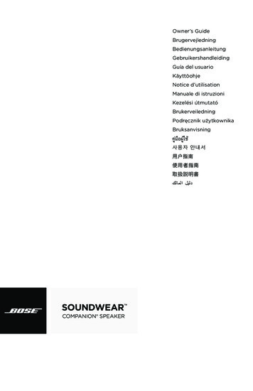
Setting UpAcoustimass module Follow these guidelines to select a location for the Acoustimass module.Note: To avoid interference with the TV picture, place the Acoustimass module at least18 inches (45 cm) from the TV.1. Place the Acoustimass module along the same the wall as the TV, or close to the sameend of the room as the front speakers (see the example along the front wall in Figure 3).2. Select a convenient location – under a table, behind a sofa. Do not allow furniture ordrapes to block the ventilation openings of the module.3. Place the Acoustimass module within reach of the audio input cable, speaker cables, andan AC power (mains) outlet.4. Select a position for the Acoustimass module (Figure 4). For proper ventilation, place it onthe long edge, with the connectors facing the floor. An alternate position is on its largestside, with the bass and treble controls facing up. Do not place the module on either end,as shown by the last two views in Figure 4.Figure 4 Acoustimass module positionsPreferredpositionAlternate positionRIGHTREARRIGHTFRONTLEFTREARCENTER LEFTFRONT OUTPUTSTOCUBE SPEAKERSTrebleBass 5. Once you have selected a position for the module, place the four self-adhesive rubber feetnear the corners of the bottom surface. The rubber feet provide increased stability andprotection from scratches.6. Aim the port (the round opening) into the room or along the wall to avoid blocking the portor creating too much bass.7. For best bass performance, do not place the port at equal distances from any two walls orfrom a wall and the ceiling.CAUTION: Do not cover the ventilation openings of the Acoustimass module. The slots onthe end provide ventilation for the built-in electronic circuitry, and should not be blocked.Music centerSelect a location for the music center.1. Allow enough room to open the CD player cover.2. Place the music center close enough to the sound sources (TV, VCR, etc.) to allow forcable length. If you need additional audio and/or video cables to connect all of yourcomponents, see your dealer or call Bose .3. Place the music center within 30 feet (9.1 m) of the Acoustimass module (the length of theaudio input cable).8December 20, 2001AM191409 01 V.pdf
Setting UpConnect the speakers and Lifestyle music center Once you have selected locations for your music system, connect the speakers.CAUTION: Make sure all components are unplugged from the power outlet before youbegin hooking up the system.Connecting the cube speaker arrays to the Acoustimassmodule Each speaker cable contains two wires. The wire marked with a red collar is positive ( ) andthe plain one is negative (–). These wires match the positive (red) and negative (black) terminals on the back of each speaker. To lengthen the cable, use standard RCA extension cablesor splice in 18-gauge or thicker cord (connecting to and – to –). To purchase cables, seeyour dealer, electronics store, or call Bose customer service.Note: The surround cables are joined together for your convenience, providing an easy-touse cable for connecting the surround speakers. To run the cables in different directions fromthe Acoustimass module, simply pull apart the cables as needed.1. Match the correct cable to the corresponding speaker location. Front speaker cables have blue connectors at one end, with L, R, and C molded intothe connectors. The red collars on the wire are labeled LEFT, RIGHT, and CENTER. Surround speaker cables have orange connectors at one end, with L and R moldedinto the connectors. The red collars on the wire are labeled LEFT and RIGHT.2. Connect the wire end of one speaker cable to the terminals on the rear of the matchingcube speaker array.a. Push each terminal tab down, then insert the end of the appropriate wire into theexposed hole. Release the tab to secure the wire. Connect each wire to its corresponding terminal positive to positive ( to ) and negative to negative (– to –).b. Repeat this step for each of the five cube speaker arrays. (See Figure 5.)Figure 5Speaker cable connections tothe cube speaker arrayCAUTION: Make sure no strands of wire from any terminal touch any other terminal.Bridged wires create short circuits that affect proper operation of your system.3. Connect each cable to the corresponding jack on the Acoustimass module.a. Plug the blue connectors into the matching left front, center, and right front jacks.b. Plug the orange connectors into the matching left surround and right surround jacks.AM191409 01 V.pdfDecember 20, 20019
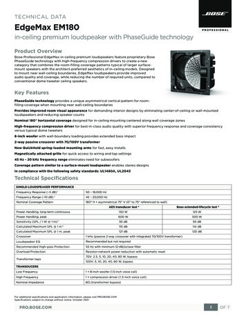
Setting UpConnecting the Acoustimass module to the Lifestyle musiccenter Connect the Acoustimass module to the music center with the audio input cable (Figure 6).1. Insert the three connectors at one end of the audio input cable into the jacks on the rearpanel of the music center: Black connector into the SYSTEM CONTROL 1 jack Red connector into the R (right) FIXED OUTPUT jack White connector into the L (left) FIXED OUTPUT jackNote: Be sure the connectors are fully inserted into each of the jacks. If the black connectoris not inserted fully into the SYSTEM CONTROL jack, you will hear no sound.Note: Do not connect the audio input cable to the SPEAKERS A or SPEAKERS B outputs(Figure 6). The speakers in your Lifestyle 12 system are designed to work properly with thefixed level audio output available from the FIXED OUTPUT jacks.2. Insert the single right-angle multi-pin connector on the other end of the audio input cableinto the AUDIO INPUT jack on the Acoustimass module. Align the connector at the angleshown in Figure 6.3. Extend the audio input cable as much as possible, since it includes an antenna for theremote control.Figure 6Right frontspeakerMusic center and speakerconnectionsCenterspeakerLeft frontspeakerRight-angleconnectorinto UTS TOCUBE SPEAKERSAudioinputcableAC powerjackBlack connectorinto SYSTEMCONTROL 1Red and white connectors intomatching FIXED OUTPUTsSPEAKERSLRBG642Z950 DT LIFESTYLE MODEL 5 MUSIC CENTERABOUTPUTSPEAKERSSBOSE CorporationUL AUXVIDEO SOUNDAMLOOPSYSTEMCONTROL1LPOWER12VAC IN1.0ARR293ABOSE CORPORATION, FRAMINGHAM, MA 01701-9168 MADE IN USA10TAPEgeprüdfteSicherheitLISTED 917DAUDIOEQUIPMENTMANUFACTURED:FIXEDLTÜV RheinlandDecember 20, 2001BOUTPUTRECPLAYINPUTANTENNAAC powerjackAM191409 01 V.pdf
Setting UpConnecting the Acoustimass module power (mains) cord1. On a dual voltage system, the voltage selector switch is preset at the factory to be correctfor your area. Check to be sure it is set for the proper voltage (Figure 7). Use 115V forNorth America; 230V for Europe and Australia. In Europe, use the adapter plug provided. Ifyou are in doubt, contact your local electric utility for the appropriate voltage setting. Figure 7Dual voltage Acoustimassmodule: voltage selector switchsettings230 V115 VCAUTION: Make sure the voltage selector switch is set correctly.2. Plug the small end of the power (mains) cord into the Acoustimass module AC power jack.Note: Do not plug the AC power cord into a power outlet until all component connectionsare complete.Connecting the music center AC (mains) power packThe Lifestyle music center comes with a 120V AC (mains) power pack for use in the USAand Canada or an appropriate 230V or 240V power pack for international use. (See Figures 1and 8.) Dual voltage models include both 120V and 230V power packs.CAUTION: Be sure to use the correct power pack for your area. Using the wrong one maydamage your power pack or your music center. Model PS71, 120V in North America Model PS74, 230V in UK or Singapore Model PS72, 230V in Europe Model PS77, 240V in AustraliaFigure 8The AC power pack(model PS71 shown1. Firmly insert the small connector on the end of the AC (mains) power pack cable into theAC POWER jack on the back of the Lifestyle music center.2. Make sure that the power pack reaches an AC (mains) outlet.Note: Do not plug the AC power pack into a power outlet until all component connectionsare complete.AM191409 01 V.pdfDecember 20, 200111
Setting UpConnecting your home theater components to the Lifestyle 12 system There are many variations of equipment in a home theater. A basic home theater systemmight include a stereo or mono TV and stereo VCR with the Lifestyle 12 system. Your hometheater can include many other combinations of equipment, including cable TV, laserdiscplayers, DVD players, CDI players, additional VCRs, and satellite decoder.Note: A mono TV only serves as a display for the video, not as a source for the audio.In order for the Lifestyle 12 system to provide home theater effects, the program materialmust be in stereo or surround-encoded, and the device playing the material must be stereo.Look for the word “surround” on the tape, CD, or preceding the TV broadcast. To hear stereoor surround sound from encoded video tapes, you must have a stereo (HiFi) VCR. While notall VCRs are stereo devices, all CD, DVD, and CDI players and nearly all laserdisc players arestereo.Note: Line level outputs from most VCRs or laserdisc players are fixed. If your VCR, laserdiscplayer, or other video sound source has fixed and variable outputs, use the fixed outputs.Setting up the primary video sound sourceThe Lifestyle 12 system has one set of video inputs for the primary source (Figure 9).Figure 9Music center connectorsBG642Z950 DT LIFESTYLE MODEL 5 MUSIC CENTERSPEAKERSSBOSE CorporationUL FIXEDTAPEAUXVIDEO SOUNDTÜV RheinlandPOWER1L12VAC IN1.0ALISTED LgeprüdfteSicherheitRR293ABRECOUTPUTBOSE CORPORATION, FRAMINGHAM, MA 01701-9168 MADE IN USAPLAYINPUTANTENNATape input Auxiliary Video soundjacksinput jacks input jacksNote: Your Lifestyle 12 system includes one 6-foot (1.8 m) stereo cable to connect the right(R) and left (L) audio outputs from a component to the music center inputs. Cables may alsob
Example of antenna grounding as per National Electrical Code, ANSI/NFPA 70. Note to CATV system installer This reminder is provided to call the CATV system installer's attention to Article 820-40 of the NEC (of USA) that provides guidelines for proper grounding. In particu-lar, it specifies that the cable ground shall be connected