Transcription
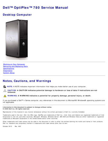
OptiPlex 7040 - Small Form FactorOwner's ManualRegulatory Model: D15SRegulatory Type: D15S003May 2020Rev. A03
ContentsChapter 1: Working on your computer. 5Before working inside your computer.5Turning off your computer. 5After working inside your computer.5Chapter 2: Removing and installing components. 6Recommended tools. 6Removing the cover. 7Installing the cover. 7Removing the front bezel. 7Installing the front bezel. 8Removing the fan duct.8Installing the fan duct.9Removing the memory module.9Installing the memory module. 9Removing the intrusion switch.9Installing the intrusion switch. 10Removing the expansion card.10Installing the expansion card.11Removing the hard drive assembly.11Removing the hard drive from the hard drive bracket. 12Installing the hard drive into the hard drive bracket. 12Installing the hard drive assembly. 13Removing the optical drive. 13Installing the optical drive. 14Removing the system fan. 15Installing the system fan. 15Removing the heat sink assembly.15Installing the heat sink assembly. 16Removing the processor. 16Installing the processor.17Removing the VGA daughter board.17Installing the VGA daughter board.18Removing the power supply unit (PSU). 18Installing the power supply unit (PSU). 20Removing the power switch.20Installing the power switch.21Removing the SD card reader.21Installing the SD card reader. 22Installing the optional SSD card. 22Removing the optional SSD card.23Removing the system board. 23Installing the system board. 25System board layout.262Contents
Chapter 3: Troubleshooting your computer.27Diagnostic and Power LED codes.27Diagnostic error messages. 32System error messages.34Chapter 4: System Setup. 36Boot Sequence.36Navigation keys.36System Setup overview. 37Accessing System Setup. 37System Setup options. 37Updating the BIOS . 44System and setup password.44Assigning a system password and setup password. 45Deleting or changing an existing system and/or setup password.45Chapter 5: Specifications. 47Chapter 6: Contacting Dell.51Contents3
Notes, cautions, and warningsNOTE: A NOTE indicates important information that helps you make better use of your computer.CAUTION: A CAUTION indicates either potential damage to hardware or loss of data and tells you how to avoidthe problem.WARNING: A WARNING indicates a potential for property damage, personal injury, or death. 2018 Dell Inc. or its subsidiaries. All rights reserved. Dell, EMC, and other trademarks are trademarks of Dell Inc. or its subsidiaries.Other trademarks may be trademarks of their respective owners.
1Working on your computerTopics: Before working inside your computerTurning off your computerAfter working inside your computerBefore working inside your computerAbout this taskTo avoid damaging your computer, perform the following steps before you begin working inside the computer.Steps1. Ensure that your work surface is flat and clean to prevent the computer cover from being scratched.2. Turn off your computer (see Turning off your computer).CAUTION: To disconnect a network cable, first unplug the cable from your computer and then unplug thecable from the network device.3. Disconnect all network cables from the computer.4. Disconnect your computer and all attached devices from their electrical outlets.5. Press and hold the power button while the computer is unplugged to ground the system board.6. Remove the cover.CAUTION: Before touching anything inside your computer, ground yourself by touching an unpainted metalsurface, such as the metal at the back of the computer. While you work, periodically touch an unpaintedmetal surface to dissipate static electricity, which could harm internal components.Turning off your computerAfter working inside your computerAbout this taskAfter you complete any replacement procedure, ensure that you connect any external devices, cards, and cables before turningon your computer.Steps1. Replace the cover.CAUTION: To connect a network cable, first plug the cable into the network device and then plug it into thecomputer.2. Connect any telephone or network cables to your computer.3. Connect your computer and all attached devices to their electrical outlets.4. Turn on your computer.5. If required, verify that the computer works correctly by running Dell Diagnostics.Working on your computer5
2Removing and installing componentsThis section provides detailed information on how to remove or install the components from your computer.Topics: Recommended toolsRemoving the coverInstalling the coverRemoving the front bezelInstalling the front bezelRemoving the fan ductInstalling the fan ductRemoving the memory moduleInstalling the memory moduleRemoving the intrusion switchInstalling the intrusion switchRemoving the expansion cardInstalling the expansion cardRemoving the hard drive assemblyRemoving the hard drive from the hard drive bracketInstalling the hard drive into the hard drive bracketInstalling the hard drive assemblyRemoving the optical driveInstalling the optical driveRemoving the system fanInstalling the system fanRemoving the heat sink assemblyInstalling the heat sink assemblyRemoving the processorInstalling the processorRemoving the VGA daughter boardInstalling the VGA daughter boardRemoving the power supply unit (PSU)Installing the power supply unit (PSU)Removing the power switchInstalling the power switchRemoving the SD card readerInstalling the SD card readerInstalling the optional SSD cardRemoving the optional SSD cardRemoving the system boardInstalling the system boardSystem board layoutRecommended toolsThe procedures in this document require the following tools: Small flat blade screwdriver Phillips screwdriver Small plastic scribe6Removing and installing components
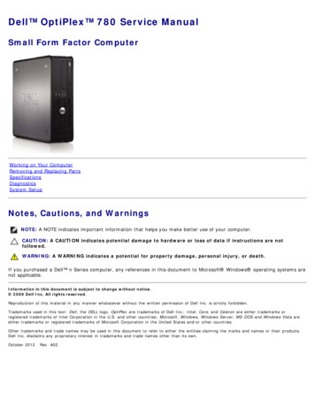
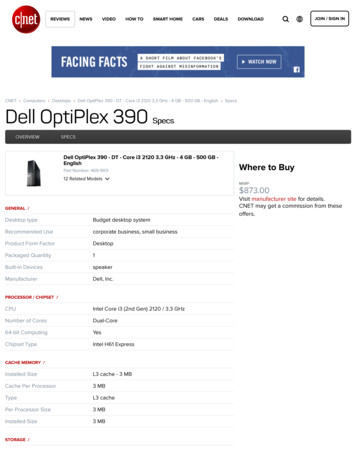
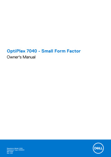
Removing the coverSteps1. Follow the procedure in Before Working Inside Your Computer.2. To remove the cover:a. Slide the blue retention tab to the right to unlock the cover [1].b. Slide the cover toward the back of the computer [2].c. Lift the cover from the computer [3].Installing the coverSteps1. Place the cover on the computer and slide the cover until it clicks into place.2. Follow the procedure in After Working Inside Your ComputerRemoving the front bezelSteps1. Follow the procedure in Before Working Inside Your Computer.2. Remove the cover.3. To remove the front bezel:a. Lift the tabs to release the front bezel from the computer [1].b. Remove the front bezel from the computer [2].Removing and installing components7
Installing the front bezelSteps1. Insert the tabs on the bezel into the slots on the computer.2. Press the bezel until the tabs clicks into place.3. Install the cover.4. Follow the procedure in After Working Inside Your ComputerRemoving the fan ductSteps1. Follow the procedure in Before Working Inside Your Computer.2. Remove the cover.3. To remove the fan duct:a. Holding the touch points, pull the fan duct bracket to release the fan duct [1].b. Lift the fan duct away from the computer [2].8Removing and installing components
Installing the fan ductSteps1. Align the slots on the fan duct, with the screws on the heat sink.2. Insert the fan duct until it clicks into place.3. Install the cover.4. Follow the procedure in After Working Inside Your Computer.Removing the memory moduleSteps1. Follow the procedure in Before Working Inside Your Computer.2. Remove the:a.b.c.d.coverfan ducthard drive assemblyoptical drive3. To remove the memory module:a. Press the memory module retention tabs on both sides of the memory module.b. Lift the memory module from the memory module connector on the system board.Installing the memory moduleSteps1. Align the notch on the memory module with the tab on the memory module connector.2. Insert the memory module into the memory module socket.3. Press the memory module until the memory module retention tabs click into place.4. Install the:a.b.c.d.optical drivehard drive assemblyfan ductcover5. Follow the procedure in After Working Inside Your Computer.Removing the intrusion switchSteps1. Follow the procedure in Before Working Inside Your Computer.Removing and installing components9
2. Remove the:a. coverb. fan duct3. To remove the intrusion switch:a. Disconnect the intrusion switch cable from the connector on the system board [1][2].b. Slide the intrusion switch and lift it away from the computer [3].Installing the intrusion switchSteps1. Insert the intrusion switch into the slot on the chassis.2. Connect the intrusion switch cable to the system board.3. Install the:a. fan ductb. cover4. Follow the procedure in After Working Inside Your Computer.Removing the expansion cardSteps1. Follow the procedure in Before Working Inside Your Computer.2. Remove the:a. coverb. fan duct3. To remove the expansion card:a. Pull the metal tab to open the expansion card latch [1].b. Pull the tab forward [2] and pull the expansion card from the connector on the computer [3].10Removing and installing components
Installing the expansion cardSteps1. Insert the expansion card into the connector on the system board.2. Press the expansion card until it clicks into place.3. Close the expansion card latch and press it until it clicks into place.4. Install the:a. fan ductb. cover5. Follow the procedure in After Working Inside Your Computer.Removing the hard drive assemblySteps1. Follow the procedure in Before Working Inside Your Computer.2. Remove the:a. coverb. fan duct3. To release the hard drive assembly:a. Push the retention tabs and remove the power connector [1,2].b. Disconnect the data and power cables from the hard drives [3, 4].Removing and installing components11
4. To remove the hard drive assembly:a. Pull the hard drive release handle forward to release the hard drive bracket from the computer [1].b. Lift the hard drive assembly away from the computer [2].Removing the hard drive from the hard drive bracketSteps1. Follow the procedure in Before Working Inside Your Computer.2. Remove the:a. coverb. bezelc. hard drive assembly3. To remove the hard drive bracket:a. Pull the hard drive bracket to release the hard drive [1].b. Lift the hard drive out of the hard drive bracket [2].Installing the hard drive into the hard drive bracketSteps1. Insert the hard drive into the hard drive bracket until it clicks into place.2. Install the:a. hard drive assembly12Removing and installing components
b. bezelc. cover3. Follow the procedure in After Working Inside Your Computer.Installing the hard drive assemblySteps1. Insert the hard drive assembly into the slot on the computer.2. Connect the power cable to the slot on the hard drive bracket.3. Install the:a. fan ductb. cover4. Follow the procedure in After Working Inside Your Computer.Removing the optical driveSteps1. Follow the procedure in Before Working Inside Your Computer.2. Remove the:a. coverb. front bezelc. hard drive assembly3. To release the optical drive:a. Remove the hard drive connector cables from the optical drive latch [1].b. Slide the blue latch to the unlock position [2].4. To remove the optical drive:a. Holding the blue latch [1], lift the optical drive cage and disconnect the cables from the optical drive. [2]b. Lift the optical drive cage away from the computer [3].Removing and installing components13
5. To remove the optical drive from the optical drive cage:a. Press the optical drive release latch [1] and slide the optical drive forward. [2]b. Remove the optical drive from the optical drive cage [3].Installing the optical driveSteps1. Slide the optical drive into the optical drive cage.2. Align the tabs on the optical cage with the slots on the computer.3. Lower the optical drive cage into the computer and lock the latch.4. Connect the data and power cables to the optical drive.5. Install the:a. hard drive assemblyb. front bezelc. cover6. Follow the procedure in After Working Inside Your Computer.14Removing and installing components
Removing the system fanSteps1. Follow the procedure in Before Working Inside Your Computer.2. Remove the:a.b.c.d.coverfront bezelhard drive assemblyoptical drive3. To remove the system fan:a. Disconnect the system fan cable from the system board [1].b. Slide the fan grommets toward the slot on the back wall [2].c. Lift the fan away from the computer. [3]Installing the system fanSteps1. Place the system fan in the computer.2. Pass the grommets through the chassis and slide outward along the groove to secure it in place.3. Connect the system fan cable to the system board.4. Install the:a.b.c.d.optical drivehard drive assemblyfront bezelcover5. Follow the procedure in After Working Inside Your Computer.Removing the heat sink assemblySteps1. Follow the procedure in Before Working Inside Your Computer.2. Remove the:a. coverb. front bezelc. fan ductRemoving and installing components15
d. hard drive assemblye. optical drive3. To remove the heat sink assembly:a. Disconnect the heat sink cable from the system board. [1]b. Loosen the captive screws that secure the heat sink assembly and lift it away from the computer [2] [3].Installing the heat sink assemblySteps1. Place the heat sink assembly onto the processor.2. Tighten the captive screws to secure the heat sink assembly to the system board.3. Connect the heat sink cable to the system board.4. Install the:a.b.c.d.e.fan ductoptical drivehard drive assemblyfront bezelcover5. Follow the procedure in After Working Inside Your Computer.Removing the processorSteps1. Follow the procedure in Before Working Inside Your Computer.2. Remove the:a.b.c.d.e.f.coverfront bezelhard drive assemblyoptical drivefan ductheat sink3. To remove the processor:a. Release the socket lever by pushing the lever down and out from under the tab on the processor shield [1].b. Lift the lever upward and lift the processor shield [2].16Removing and installing components
c. Lift the processor out of the socket [3].Installing the processorSteps1. Align the processor with the socket keys.2. Align the pin-1 indicator of the processor with the triangle on the socket.3. Place the processor on the socket such that the slots on the processor align with the socket keys.4. Close the processor shield by sliding it under the retention screw.5. Lower the socket lever and push it under the tab to lock it.6. Install the:a.b.c.d.e.f.heat sinkfan ductoptical drivehard drive assemblyfront bezelcover7. Follow the procedure in After Working Inside Your Computer.Removing the VGA daughter boardSteps1. Follow the procedure in Before Working Inside Your Computer.2. Remove the:a. coverb. fan duct3. To remove the VGA daughter board:a.b.c.d.Remove the screws that secure the VGA connector to the computer [1].Slide the VGA connector to release it from the computer [2].Remove the screw that secures the VGA daughter board to the computer [3].Lift the VGA daughter board using the handle to remove it from the computer [4].Removing and installing components17
Installing the VGA daughter boardSteps1. Align the VGA daughter board with the screw holder on the system board.2. Tighten the screw to secure the VGA daughter board to the system board.3. Insert the VGA connector into the slot at the back of the computer.4. Tighten the screws to secure the VGA connector to the computer.5. Install the:a. fan ductb. cover6. Follow the procedure in After Working Inside Your Computer.Removing the power supply unit (PSU)Steps1. Follow the procedure in Before Working Inside Your Computer.2. Remove the:a.b.c.d.e.coverfront bezelhard drive assemblyoptical drivefan duct3. To release the PSU:a. Disconnect the power cable from the system board [1] [2].b. Unroute the power cables from the retention clips on the chassis [3] [4].18Removing and installing components
4. To remove the PSU:a. Disconnect the power cable from the system board [1] [2].b. Lift the cables away from the computer [3].c. Remove the screws that secure the PSU to the computer [4].5. Press the blue release tab [1], slide the PSU and lift it away from the computer [2].Removing and installing components19
Installing the power supply unit (PSU)Steps1. Insert the PSU in the chassis and slide it toward the back of the computer to secure it.2. Tighten the screws to secure the PSU to the back of the computer.3. Route the PSU cables through the retention clips.4. Connect the power cables to the system board.5. Install the:a.b.c.d.e.fan ductoptical drivehard drive assemblyfront bezelcover6. Follow the procedure in After Working Inside Your Computer.Removing the power switchSteps1. Follow the procedure in Before Working Inside Your Computer.2. Remove the:a.b.c.d.e.coverfront bezelhard drive assemblyoptical drivepower supply unit3. To remove the power switch:a. Disconnect the power switch cable from the system board [1].b. Press the power switch retention tabs and remove it from the chassis [2] [3].20Removing and installing components
Installing the power switchSteps1. Slide the power switch module into the slot on the chassis until it clicks into place.2. Connect the power switch cable to the connector on the system board.3. Install the:a.b.c.d.e.power supply unitoptical drivehard drive assemblyfront bezelcover4. Follow the procedure in After Working Inside Your Computer.Removing the SD card readerSteps1. Follow the procedure in Before Working Inside Your Computer.2. Remove the:a.b.c.d.e.coverfront bezelhard drive assemblyoptical drivepower supply unit3. To remove the SD card reader:a. Remove the power supply unit cables from the retention clips on the SD card reader enclosure [1].b. Remove the screws that secure the SD card reader and lift it away from the computer [2] [3].Removing and installing components21
Installing the SD card readerSteps1. Place the SD card reader on the chassis.2. Tighten the screws that secure the SD card reader to the computer.3. Route the power supply unit cables into the retention clips.4. Install the:a.b.c.d.e.power supply unitoptical drivehard drive assemblyfront bezelcover5. Follow the procedure in After Working Inside Your Computer.Installing the optional SSD cardSteps1. Remove the:a. coverb. front bezel2. Peel the adhesive tape (blue) from the rubber.22Removing and installing components
3. Place the rubber on the computer [1] and peel the adhesive tape (pink) from the rubber [2].4. To install the SSD card:a. Connect the SSD card to the connector on the system board [1].b. Tighten the screw to secure the SSD card to the system board [2].Removing the optional SSD cardSteps1. Follow the procedure in Before Working Inside Your Computer.2. Remove the: cover front bezel3. Remove the screw that secures the SSD card to the system board.4. Disconnect the SSD card from the connector on the system board.5. Remove the rubber from the system board.Removing the system boardSteps1. Follow the procedure in Before Working Inside Your Computer.2. Remove the:Removing and installing components23
a.b.c.d.e.f.g.h.i.j.k.l.coverfan ductfront bezelmemory modulehard drive assemblyoptical driveexpansion cardoptional SSD cardSD card readerVGA daughter boardheat sinkprocessor3. To remove the I/O panel:a. Remove the screw that secures the I/O panel to the chassis [1].b. Remove the I/O panel from the computer [2].4. Disconnect all the cables connected to the system board.5. To remove the system board:a. Remove the screws that secure the system board to the computer [1].b. Slide the system board toward the front of the computer and lift it from the computer [2].24Removing and installing components
Installing the system boardSteps1. Hold the system board by its edges and angle it toward the back of the computer.2. Lower the system board into the computer until the connectors at the back of the system board align with the slots on theback wall of the computer, and the screw holes on the system board align with the standoffs on the computer.3. Tighten the screws that secure the system board to the computer.4. Connect the cables to the system board.5. Install the:a.b.c.d.e.f.g.h.i.j.k.l.VGA daughter boardSD card readeroptional SSD cardexpansion cardprocessorheat sinkoptical drivehard drive assemblymemory modulefront bezelfan ductcover6. Place the I/O panel on the chassis.7. Tighten the screws to secure the I/O panel to the chassis.8. Follow the procedure in After Working Inside Your Computer.Removing and installing components25
System board layout1. PCIex16 connector3. RJ-45/USB 2.0 connector5. PS2 keyboard/MS connector7. DisplayPort connector9. Line-out connector11. Intrusion switch connector13. Processor15. Memory module connectors17. Power switch connector19. System fan connector21. Universal audio jack23. USB 3.0 connector25. SATA0 connector27. Internal speaker connector29. Internal USB connector31. Coin cell battery26Removing and installing components2. PCIex4 connector4. USB 3.0 connector6. Serial port connector8. HDMI connector10. CPU power connector12. VGA daughter board connector14. CPU fan connector16. M.2 socket3 connector18. Media card reader connector20. Hard drive activity LED22. USB 2.0 connector24. ATX power connector26. SATA2 connector28. Hard drive and optical drive power cable connector30. SATA1 connector
3Troubleshooting your computerYou can troubleshoot your computer using indicators like diagnostic lights, beep codes, and error messages during the operationof the computer.Topics: Diagnostic and Power LED codesDiagnostic error messagesSystem error messagesDiagnostic and Power LED codesTable 1. Power LED statesPower LED light statusPossible causeTroubleshooting stepsOffThe computer is either turnedoff or is not receiving poweror in Hibernation mode. Re-seat the power cablein the power connector onthe back of the computerand the electrical outlet. If the computer is pluggedinto a power strip,ensure that the powerstrip is plugged into anelectrical outlet and isturned on. Also, bypasspower protection devices,power strips, and powerextension cables to verifythat the computer turnson properly. Ensure the electrical outletis working by testing itwith another device, suchas a lamp.Solid amber / blinking amberThe second state of the LEDat power up, indicates thatthe POWER GOOD signal isactive and it is
Removing the cover. Steps. 1. Follow the procedure in Before Working Inside Your Computer. 2. To remove the cover: a. Slide the blue retention tab to the right to unlock the cover [1].