Transcription
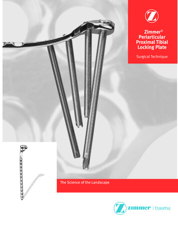
Zimmer PeriarticularProximal TibialLocking PlateSurgical TechniqueThe Science of the Landscape
1Zimmer Periarticular Proximal Tibial Locking PlateTable of ContentsIntroductionLocking Screw TechnologyLocking Plate TechnologyPlate FeaturesIndicationsFracture Classification222333Surgical Techniquefor the Periarticular 5.5mm Proximal Tibial Locking PlateRequired InstrumentationPreoperative PreparationSurgical ApproachFracture ReductionPlate PositioningScrew TrajectoryFracture FixationWound ClosurePostoperative TreatmentImplant RemovalInstruments and ImplantsOrder Information444466991616161720Surgical Techniquefor the Periarticular 3.5mm Proximal Tibial Locking PlateRequired InstrumentationPreoperative PreparationSurgical ApproachFracture ReductionPlate PositioningScrew TrajectoryFracture FixationWound ClosurePostoperative TreatmentImplant RemovalInstruments and ImplantsOrder Information21212121222224253030303134
2Zimmer Periarticular Proximal Tibial Locking PlateIntroductionThe Zimmer Periarticular LockingPlate System combines locking screwtechnology with periarticular plates tocreate fixed-angle constructs for use incomminuted fractures or where deficientbone stock or poor bone quality isencountered. The fixed-angle plate/screw device can be used in osteopenicbone and other areas where traditionalscrew fixation may be compromised.The Periarticular Locking Plates willaccommodate standard screws, as wellas locking screws with threaded heads.When necessary, interfragmentarycompression can be achieved usingstandard screws in the dualcompression slots.Cannulated screws and instrumentsallow provisional fixation with guidepins in the metaphysis. This helpsensure that the threaded locking screwheads align properly with thethreaded plate holes.All plate configurations contain lockingscrew holes in the plate head, andalternating locking and compressionscrew slots in the shaft.Locking Screw TechnologyThe heads of the locking screws containmale threads while the holes in theplates contain female threads. Thisallows the screw head to be threadedinto the plate hole, locking the screwinto the plate. This technical innovationprovides the ability to create afixed-angle construct while usingfamiliar plating techniques.Locking Plate TechnologyBy using locking screws in a bone plate,a fixed-angle construct is created.In osteopenic bone or fractures withmultiple fragments, secure bonepurchase with conventional screws maybe compromised. The locking screws donot rely on bone/plate compression toresist patient load, but function similarlyto multiple small angled blade plates.In osteopenic bone or comminutedfractures, the ability to lock screws intoa fixed-angle construct is imperative.By combining locking screw holes withcompression screw slots in the shaft,the plate can be used as both a lockingdevice and a fracture compressiondevice. If compression is desired,it must be achieved first by insertingthe standard screws in the compressionscrew slots before inserting anylocking screws.The locking plate design does notrequire compression between the plateand bone to accommodate loading.Therefore, purchase of the screws inthe bone can be achieved with a threadprofile that is shallower than that oftraditional screws. The shallow threadprofile, in turn, allows for screws witha large core diameter to accommodateloading with improved bending andshear strength.
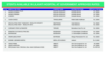
3Zimmer Periarticular Proximal Tibial Locking PlatePlate FeaturesFracture Classification Anatomically contoured platesare precontoured to create a fitthat requires little or no additionalbending and helps with metaphyseal/diaphyseal reductionRefer to the OTA Fracture andDislocation Compendium, or theSchatzker classification below formore information. The low profile plate facilitatesfixation without impinging onsoft tissue5.5mm Proximal Tibial Locking Plate.3.5mm Proximal Tibial Locking Plate. The plate can be used to controla medial fracture fragment 3.5mm Proximal Lateral Tibial LockingPlates are available in six lengths,from 6 hole (104mm ) to16 hole (224mm)The anatomical shapeof the head of the platematches the shape ofthe proximal tibia 5.5mm Proximal Lateral Tibial LockingPlates are available in six lengths,from 4 hole (97mm ) to14 hole (250mm)Multiple locking holesin the plate head allowplacement of the screwsto capture fragments Dual compression slots willaccommodate periarticular screws orconventional stainless steel screwsand allow bi-directional compressionThick-to-thin plateprofiles make the platesautocontourable The last diaphyseal plate hole isdesigned to accommodate thetension device (00-4817-000-05)IndicationsThe Periarticular Locking Plate Systemis indicated for temporary internalfixation and stabilization of osteotomiesand fractures, including: Comminuted fractures Supracondylar fracturesThe plate shaft designallows for a minimallyinvasive technique withsubmuscular passage ofthe plate Intra-articular and extra-articularcondylar fractures Fractures in osteopenic bone Nonunions MalunionsFig. 1. Zimmer Periarticular Proximal Tibial Locking Plate features.
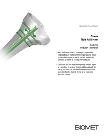
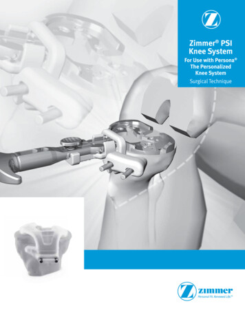
4Zimmer Periarticular Proximal Tibial Locking PlateSurgical Techniquefor the Periarticular 5.5mmProximal Tibial Locking PlateRequired InstrumentationThe following sets may be required forapplication of the 5.5mm PeriarticularLocking Proximal Tibia Plates:Preoperative PreparationAfter assessing the fractureradiographically and preparing apreoperative plan, place the patient inthe supine position on a radiolucenttable. Be sure that the fluoroscope canbe positioned to visualize the proximaltibia in both the lateral and Anterior/Posterior (A/P) views. 5.5mm/4.5mm Locking Screw andInstrument SetPre-operative planning using A/P andM/L templating will allow assessment ofthe ability of the lateral plate to captureand adequately stabilize any medialfragments. If adequate reduction orfixation is not feasible, a medial buttressplate should also be considered. 5.5mm Locking Proximal Tibia Plateand Standard Jig SetSurgical Approach Standard Screw Set Basic Instrument Set Basic Forcep Set Linear Bone ClampsThe patient is positioned supine ona radiolucent operating table.A straight lateral parapatellar incisionis made (Fig. 2). This incision can beextended proximally and/or distally asmore exposure is required.The dissection should go straight downto the bone by detaching the anteriorcompartment muscle origins andsplitting the fibers of the iliotibial tract.The knee joint is then opened below thelateral meniscus in order to get a goodview of the articular surface.Do not dissect across the tibialtuberosity – unless absolutely necessary– the soft tissue coverage on the medialside is very delicate. Take care not toplace incisions over the proposed sitesof implants, or where there is risk ofdevitalizing sensitive structures.When treating fractures with a bicondylarcomponent, an additional posteromedialincision is recommended to ensureanatomic reduction of the medial cortex(Fig. 3). Use of the linear bone clampsgreatly facilitates reduction of this typeof fracture (Fig. 4).Fig. 2Fig. 3
Zimmer Periarticular Proximal Tibial Locking PlateFig. 45
6Zimmer Periarticular Proximal Tibial Locking PlateFracture ReductionCentral Proximal HoleIt is imperative that accurate reductionof the fracture be obtained prior to andmaintained during application of theproximal tibial plate.Reduce the intra-articular fragmentsusing linear bone clamps or Kirschnerwires to temporarily hold the reduction.Use lag screws to secure the intraarticular fragments. To help avoidinserting the lag screws where they willinterfere with the plate placement, holdthe plate on the bone in its approximateposition. Then insert the lag screwsas needed – the lag screws can oftenbe placed through the plate usingcannulated conical screws, or may beinserted in subchondral bone proximalto the plate.Strut Screw HoleFig. 5Plate PositioningHold the appropriate (left or right)Metaphyseal Jig (Fig. 5) on the selectedplate and finger tighten the set screw.Insert the 5.5mm Standard Jig Sleeveinto the CENTRAL PROXIMAL hole ofthe jig (Fig. 6) and thread the 3.2mmStandard Cannula into the plate hole(Fig. 7) through the Jig Sleeve.Fig. 6Note: The Cannula Inserter may be usedto tighten cannulas.Cannula InserterFig. 7
Zimmer Periarticular Proximal Tibial Locking PlateBefore placing the plate on the bone,insert additional 5.5mm Standard JigSleeves into each of the most proximalholes in the Metaphyseal Jig, then threada 3.2mm Standard Cannula into the plate(Fig. 8) through each of the sleeves.It is easier to thread the cannulas intothe plate holes before the plate isapplied to the bone. The cannulas canbe used as handles to position the plate.Use this construct to place the initial3.2mm Drill Tip Guide Wire in themetaphysis. Check plate placement– visually and fluoroscopically to ensurethat the plate is positioned correctlyon the metaphysis of the bone. UseA/P and lateral fluoroscopic images toposition the plate. Note: The position ofthe plate on the bone must be verifiedbecause there is a tendency to placethe distal end of the plate too posterioron the tibial shaft. Posterior placementcan cause the locking screws to beplaced at a tangent and can result ininsufficient holding strength. Becausethe tibial shaft may not be alignedwith the proximal fragment, the platehead should be used to determine theappropriate placement of the plate. Theplate head should conform to the shapeof the intact or reconstructed proximaltibia. This will determine the alignmentof the shaft.Fig. 8Warning: Do not contour or bendthe plate at or near a threaded hole,as doing so may deform the threadedhole and cause incompatibility with thelocking screw.Hold the plate in the desired position(Fig. 9) and insert a 3.2mm Drill TipGuide Wire through the central GuideWire Cannula in the head of the plateuntil the tip engages the oppositecortical wall. Use the fluoroscope toconfirm the position of the wire in boththe A/P and lateral planes. Adjust thewire location if necessary. If preferred,use a linear bone clamp or bonereduction instrument to secure the plate.Fig. 97
8Zimmer Periarticular Proximal Tibial Locking PlateWhen the first wire is satisfactory,adjust the plate rotation, if necessary.The next step is to align the plate shaftwith the tibial shaft. Insert a 3.7mmcannula into the most distal plate shafthole. Use the 3.7mm drill bit throughthe cannula. Make certain under A/Pand lateral fluoroscopy that the plateshaft and tibial shaft are alignedproperly. Measure for the 4.5mm lockingscrew length using the 5.5mm/4.5mmstandard locking screw depth gauge.Insert the 4.5mm locking screw. Theninsert additional 3.2mm Drill Tip GuideWires (Fig. 10) through the otherproximal Guide Wire Cannulas to helpprevent rotation of the plate.If desired, after removal of themetaphyseal jig, additional 1.6mmDrill Tip Guide Wires can be insertedthrough the proximal K-wire holes tofurther stabilize the plate (Fig. 11). Usethe fluoroscope for both A/P and lateralviews to confirm the position of the platehead, shaft, and guide wires. The guidewires should be parallel to the joint line.Fig. 10Fig. 11
9Zimmer Periarticular Proximal Tibial Locking PlateScrew TrajectoryFracture FixationMetaphyseal Screw FixationOnce the plate is properly positioned,slide the 5.5mm Cannulated ScrewDepth Gauge (Fig. 12) over the guidewires to measure for the screw lengths.The tip of the gauge must contact theend of the guide wire cannula for anaccurate measurement. This will positionthe tip of the screw at the tip of the guidewire. Read the proper screw length fromthe guide.Predrilling and tapping are typically notnecessary as the flutes of the screwsare self-drilling and self-tapping. If thebone is dense, the lateral cortex can bepredrilled using the 4.7mm CannulatedDrill and, if necessary, tapped using the5.5mm Cannulated Screw Tap.Note: If required, lag screw reductionof a fragment or compression of thearticular surface must be accomplishedbefore inserting any locking screws.The 5.5mm Cannulated Conical Screwscan be used for lag screw fixation.Fig. 12
10Zimmer Periarticular Proximal Tibial Locking PlateSlide the Screwdriver Stop Ring onto thescrewdriver shaft and place it at the levelof the black ring etched on the drivershaft (Fig. 13). Before the Blue StopRing approaches the top of the JigSleeve, power insertion should stop.Screws must be seated by hand. TheScrewdriver Stop Ring is intended to bea visual cue to stop power insertionof the locking screws.Remove the Guide Wire Cannulas anduse the 5.0mm Hex Cannulated Driver(Fig. 14) to insert a 5.5mm CannulatedConical or 5.5mm Cannulated LockingScrew over each of the guide wires andinto the three proximal holes. Sleevesand cannulas may be inserted into thetwo additional proximal plate holes iflocked screws are necessary in theseholes. Follow the same procedure foreach proximal screw.Fig. 13Note: A screwdriver shaft can beused to loosely insert the screw underpower, but the final seating must beaccomplished by hand to avoidcross-threading of the screws in theplate holes or breakage of thescrew or driver.Note: Screws inserted into the secondrow of metaphyseal holes should beless than 80mm in length to avoidinterference with the other screws.Be sure that all screws aresecurely tightened.Note: If the plate shifts during screwinsertion, all the pins and screws mustbe removed and reinserted for thescrews to lock properly to the plate.Note: If a plate screw impinges onone of the intra-articular lag screws,the lag screw must be removed andrepositioned.Fig. 14
Zimmer Periarticular Proximal Tibial Locking PlateUse direct or indirect reductiontechniques to reduce the proximal tibiato the shaft. Confirm that the leg is inproper rotation. Temporarily secure theplate shaft to the bone with plate holdingforceps, a nonlocking screw or the5.5mm Plate Reduction Instrument.If lag screws will be used through someof the holes in the shaft, insert the firstlag screw to reduce the plate to the bone.Shaft FixationIf both locking and nonlocking screwswill be used in the shaft, the nonlockingscrews must be inserted first. Insertstandard cortical screws through thecompression slots in the plateas desired.Apply the appropriate drill guide(Fig. 15) (4.5mm/3.2mm Double DrillGuide, 4.5mm Universal Drill Guide,4.5mm Compression Drill Guide or6.5mm/3.2mm Double Drill Guide)to one of the nonlocking slots in theshaft. Use the 3.2mm Standard Drill(Fig. 16) to drill through both cortices.Fig. 15Fig. 1611
12Zimmer Periarticular Proximal Tibial Locking PlateUse the Depth Gauge to measure theappropriate screw length (Fig. 17). Theninsert a self-tapping lag screw (Fig. 18).Check the position of the screw withthe fluoroscope. Repeat this procedurefor each of the standard screwsto be inserted.Fig 17Fig 18
13Zimmer Periarticular Proximal Tibial Locking PlateTo insert locking screws, thread the3.7mm Standard Cannula into the mostproximal shaft locking hole of the plate(Fig. 19). Use the 3.7mm StandardDrill through the cannula to drill a pilothole (Fig. 20). Check the depth andposition of the drill with fluoroscopicFig. 19Fig. 20
14Zimmer Periarticular Proximal Tibial Locking Plateimages. Remove the cannula and usethe Depth Gauge (Fig. 21) to measure theappropriate screw length. Then insert thelocking screw (Fig. 22).Tapping is typically not necessary as theflutes of the screws are self-drilling andself-tapping. If the bone is dense, thelateral cortex can be tapped using the4.5mm Locking Screw Tap.Insert additional locking screwsas desired.Fig. 21Fig. 22
Zimmer Periarticular Proximal Tibial Locking PlateStrut Screw FixationA locking strut screw can be insertedinto the plate to support a medialfragment. Insert a 5.5mm Jig Sleeveand a 3.2mm Standard Cannula(Fig. 23) into the oblique locking hole.Then insert a 3.2mm Drill Tip GuideWire through the Cannula (Fig. 24) untilthe tip engages the medial corticalwall. Use the fluoroscope to confirmthe position of the wire in both theA/P and lateral planes.Note: To avoid interference with otherscrews, the Strut Screw should be 80mmin length or shorter.Fig. 23Fig. 2415
16Zimmer Periarticular Proximal Tibial Locking PlateRemove the Guide Wire Cannula anduse the 5.0mm Hex Cannulated Driver(Fig. 25) to insert a Cannulated Conicalor Locking Screw over the guide wire.Make a final check of the limb alignmentand fracture reduction. Then makesure that all locking screws in the headand shaft are securely tightenedbefore closing.Wound ClosureUse the appropriate method for surgicalclosure of the incision.Postoperative TreatmentPostoperative treatment with lockingplates does not differ from conventionalopen reduction internal fixation (ORIF)procedures. Limited weight-bearing andearly knee motion are recommended.Fig. 25Implant RemovalTo remove locking screws, use the largehexagonal screwdriver, 5.0mm hex tofirst unlock all screws from the plate andthen remove screws completely. Do notuse the Forward Captive Drivers forscrew removal.Please refer to the package insertfor product information, includingcontraindications, warnings, andprecautionary information.
17Zimmer Periarticular Proximal Tibial Locking PlateInstrument and Implants5.5mm Proximal Lateral Tibial Plate Jig,Right 00-2360-091-01, Left 00-2360-091-025.5mm/4.5mm Standard Jig Sleeve 00-2360-090-043.2mm Standard Cannula 00-2360-021-325.5mm/4.5mm Cannula Inserter 00-2360-088-003.2mm Standard Drill Tip Guide Wire 00-2360-033-32Guide Wire Inserter 00-2360-085-005.5mm Cannulated Locking Screw Depth Gauge00-2360-041-554.7mm Std Cannulated Drill 00-2360-071-47
18Zimmer Periarticular Proximal Tibial Locking Plate5.0mm Hex Std Cannulated Screwdriver 00-2360-066-50Modular Handle 00-2360-186-003.7mm Standard Cannula 00-2360-020-373.7mm Std Drill 00-2360-225-374.5mm Locking Screw Standard Depth Gauge00-2360-040-454.5mm Locking Screw Tap 00-2360-053-455.0mm Hex Std Screwdriver 00-2360-065-505.0mm Screwdriver Stop Ring 00-2360-065-05
19Zimmer Periarticular Proximal Tibial Locking Plate3211 5.5mm / 4.5mm Locking Plate Reduction Instrument00-2360-012-012 5.5mm / 4.5mm Plate Reduction Sleeve 00-2360-012-023 Spin Knob 00-2360-012-035.5mm Std Cannulated Locking Screw Tap 00-2360-054-55
20Zimmer Periarticular Proximal Tibial Locking PlateOrder InformationPart 800-2357-006-045.5mm Proximal Tibial Plate Standard Jig Set5.5mm Proximal Lateral Tibial Plate Jig, Right5.5mm Proximal Lateral Tibial Plate Jig, Left5.5mm Proximal Lateral Tibial Plate/Jig CaseStandard Jig Set Screw 2 ea.5.5mm Prox Lat Tib Lck Plt Set5.5mm Proximal Lateral Tibial Locking Plate,4 Hole, 97mm Long, Left5.5mm Proximal Lateral Tibial Locking Plate,6 Hole, 128mm Long, Left5.5mm Proximal Lateral Tibial Locking Plate,8 Hole, 158mm Long, Left5.5mm Proximal Lateral Tibial Locking Plate,10 Hole, 189mm Long, Left5.5mm Proximal Lateral Tibial Locking Plate,12 Hole, 219mm Long, Left5.5mm Proximal Lateral Tibial Locking Plate,14 Hole, 250mm Long, Left5.5mm Proximal Lateral Tibial Locking Plate,4 Hole, 97mm Long, Right5.5mm Proximal Lateral Tibial Locking Plate,6 Hole, 128mm Long, Right5.5mm Proximal Lateral Tibial Locking Plate,8 Hole, 158mm Long, Right5.5mm Proximal Lateral Tibial Locking Plate,10 Hole, 189mm Long, Right5.5mm Proximal Lateral Tibial Locking Plate,12 Hole, 219mm Long, Right5.5mm Proximal Lateral Tibial Locking Plate,14 Hole, 250mm Long, 57-005-14Also 1-4700-2360-225-375.5mm Proximal Lateral Tibial Locking Plate,18 Hole, 311mm Long, Left, Sterile Only5.5mm Proximal Lateral Tibial Locking Plate,22 Hole, 372mm Long, Left, Sterile Only5.5mm Proximal Lateral Tibial Locking Plate,18 Hole, 311mm Long, Right, Sterile Only5.5mm Proximal Lateral Tibial Locking Plate,22 Hole, 372mm Long, Right, Sterile Only5.5mm/4.5mm Periarticular Locking Screwand Instrument SetCleaning StyletCleaning Brush5.5mm/4.5mm Locking Screw Instrument Case5.5mm/4.5mm Plate Reduction Instrument5.5mm/4.5mm Plate Reduction SleevePlate Reduction Spin Knob3.7mm Standard Cannula3.2mm Standard Cannula3.2mm Standard Drill Tip Guide Wire(5 per box)4.5mm Locking Screw Standard Depth Gauge5.5mm Cannulated Locking Screw Depth Gauge4.5mm Locking Screw Tap5.5mm Cannulated Locking Screw Tap5.0mm Hex Standard Screwdriver5.0mm Hex Standard Cannulated Screwdriver4.7mm Standard Cannulated Drill3.7mm Standard -04Guide Wire InserterModular Handle5.5mm/4.5mm Cannula Inserter5.0mm Screwdriver Stop RingTorque Limiting AttachmentLarge Hex Screwdriver (1 ea.)5.5mm/4.5mm Standard Jig Sleeve (4 m Locking Screw Set5.5mm Cannulated Locking Screw 30mm Long5.5mm Cannulated Locking Screw 35mm Long5.5mm Cannulated Locking Screw 40mm Long5.5mm Cannulated Locking Screw 45mm Long5.5mm Cannulated Locking Screw 50mm Long5.5mm Cannulated Locking Screw 55mm Long5.5mm Cannulated Locking Screw 60mm Long5.5mm Cannulated Locking Screw 65mm Long5.5mm Cannulated Locking Screw 70mm Long5.5mm Cannulated Locking Screw 75mm Long5.5mm Cannulated Locking Screw 80mm Long5.5mm Cannulated Locking Screw 85mm Long5.5mm Cannulated Locking Screw 90mm Long5.5mm Cannulated Locking Screw 95mm Long5.5mm Cannulated Locking Screw 100mm Long5.5mm Cannulated Conical Screw 50mm Long5.5mm Cannulated Conical Screw 55mm Long5.5mm Cannulated Conical Screw 60mm Long5.5mm Cannulated Conical Screw 65mm Long5.5mm Cannulated Conical Screw 70mm Long5.5mm Cannulated Conical Screw 75mm Long5.5mm Cannulated Conical Screw 80mm Long5.5mm Cannulated Conical Screw 85mm Long5.5mm Cannulated Conical Screw 90mm Long4.5mm Locking Screw 12mm long4.5mm Locking Screw 14mm long4.5mm Locking Screw 16mm long4.5mm Locking Screw 18mm long4.5mm Locking Screw 20mm long4.5mm Locking Screw 22mm long4.5mm Locking Screw 24mm long4.5mm Locking Screw 26mm long4.5mm Locking Screw 28mm long4.5mm Locking Screw 30mm long4.5mm Locking Screw 32mm long4.5mm Locking Screw 34mm long4.5mm Locking Screw 36mm long4.5mm Locking Screw 38mm long4.5mm Locking Screw 40mm long4.5mm Locking Screw 42mm long4.5mm Locking Screw 44mm long4.5mm Locking Screw 46mm long4.5mm Locking Screw 48mm long4.5mm Locking Screw 50mm long4.5mm Locking Screw 55mm long4.5mm Locking Screw 60mm long4.5mm Locking Screw 65mm long4.5mm Locking Screw 70mm long
21Zimmer Periarticular Proximal Tibial Locking PlateSurgical Techniquefor the Periarticular 3.5mmProximal Tibial Locking PlateRequired InstrumentationThe following sets may be required forapplication of the 3.5mm PeriarticularLocking Proximal Tibia Plate:Preoperative PreparationAfter assessing the fractureradiographically and preparing apreoperative plan, place the patient inthe supine position on a radiolucenttable. Be sure that the fluoroscope canbe positioned to visualize the proximaltibia in both the lateral and Anterior/Posterior (A/P) views. Basic Forceps SetThrough A/P and M/L templating, assessthe ability of the lateral plate to captureand adequately stabilize any medialfragments. If adequate fixation is notfeasible, a medial buttress plate shouldalso be considered. 3.5mm/2.7mm Locking Screwand Instrument SetSurgical Approach 3.5mm Locking Proximal Tibia Plateand Standard Jig SetThe patient is positioned supine on aradiolucent operating table.NOTE: The 2.7mm Locking Screwsshould not be used with the 3.5mmLocking Proximal Tibial Plate.A straight lateral parapatellar incisionis made. This incision can be extendedproximally and/or distally as moreexposure is required (Fig. 26). Small Fragment Screw andInstrument Set Cannulated ScrewsFig. 26The dissection should go straight downto the bone by detaching the lateralmuscle origins and splitting the fibersof the iliotibial tract. The knee joint isthen opened below the lateral meniscusin order to get a good view of thearticular surface.Do not dissect across the tibialtuberosity – unless absolutely necessary– the soft tissue coverage on the medialside is very delicate. Take care not toplace incisions over the proposed sitesof implants, or where there is risk ofdevitalizing sensitive structures.When treating fractures with a bicondylarcomponent, an additional posteromedialincision is recommended (Fig. 27).Fig. 27
22Zimmer Periarticular Proximal Tibial Locking PlateFracture ReductionCentral Proximal HolesIt is imperative that accurate reductionof the fracture be obtained prior to orthrough application of the plate andmaintained during application of theproximal tibial plate.Reduce the intra-articular fragmentsusing linear bone clamps or Kirschnerwires to temporarily hold the reduction.Use lag screws to secure the intraarticular fragments. To help avoidinserting the lag screws where they willinterfere with the plate placement, holdthe plate on the bone in its approximateposition. Then insert the lag screwsas needed – the lag screws can oftenbe placed through the plate usingcannulated conical screws, or may beinserted in subchondral bone proximalto the plate.Strut Screw HoleFig. 28Plate PositioningHold the appropriate Metaphyseal Jig(Fig. 28) on the selected plate and fingertighten the set screw. Insert the 3.5mmStandard Jig Sleeve into one of the mostproximal holes of the Jig and thread the1.6mm Standard Cannula into the platehole (Fig. 29).Before placing the plate on thebone, using the Jig Sleeve, threadthe appropriate number of StandardCannulas into each of the other proximalholes in the head of the plate (Fig. 30).It is easier to thread the cannulas intothe plate holes before the plate isapplied to the bone. The cannulas canbe used as handles to position the plate.Fig. 29Note: Cannulas in the proximal row ofthe jig cannot be inserted next to oneanother.Cannula InserterFig. 30
23Zimmer Periarticular Proximal Tibial Locking PlateUse this construct to place the initial1.6mm Drill Tip Guide Wire in themetaphysis. Check plate placement– visually and fluoroscopically to ensurethat the plate is positioned correctly onthe metaphysis of the bone. If placementis appropriate, hold the Jig on the plateand finger tighten the set screw.Use A/P and lateral fluoroscopic imagesto position the plate. Note: The positionof the plate on the bone must be verifiedbecause there is a tendency to placethe distal end of the plate too posterioron the tibial shaft. Posterior placementcan cause the locking screws to beplaced at a tangent and can result ininsufficient holding strength. Becausethe tibial shaft may not be alignedwith the proximal fragment, the platehead should be used to determine theappropriate placement of the plate.The plate head should conform to theshape of the intact or reconstructedproximal tibia. This will determine thealignment of the shaft.Hold the plate in the desired positionand insert a 1.6mm Drill Tip Guide Wire(Fig. 31) through one of the centralGuide Wire Cannulas until the tipengages the opposite cortical wall. Usethe fluoroscope to confirm the positionof the wire in both the A/P and lateralplanes. Adjust the wire location ifnecessary. If preferred, use a linear boneclamp or bone reduction instrumentto secure the plate.When the first wire is satisfactory, adjustthe plate rotation, if necessary. The nextstep is to align the plate shaft with thetibial shaft. Insert a 2.7mm standardcannula into the most distal plate shafthole. Use the 2.7mm drill bit through thecannula. Make certain under A/P andlateral fluoroscopy that the plate shaftand tibial shaft are aligned properly.Measure for the 3.5mm locking screwlength using the 3.5mm/2.7mmstandard locking screw depth gauge.Insert the 3.5mm locking screw. Theninsert Drill Tip Guide Wires through theother proximal Guide Wire Cannulasto help prevent rotation of the plate.Note: If desired, after removal of themetaphyseal jig, additional 1.6mm DrillTip Guide Wires can be inserted throughthe proximal K-wire holes to furtherstabilize the plate (Fig. 32).Use the fluoroscope for both A/P andlateral views to confirm the position ofthe plate head, shaft, and guide wires.The guide wires should be parallel tothe joint line.Warning: Do not contour or bendthe plate at or near a threaded hole,as doing so may deform the threadedhole and cause incompatibility with thelocking screw.Fig. 31Fig. 32
24Zimmer Periarticular Proximal Tibial Locking PlateScrew TrajectoryFig. 33
Zimmer Periarticular Proximal Tibial Locking PlateFracture FixationMetaphyseal Screw FixationIf required, lag screw reduction of afragment or compression of the articularsurface must be accomplished beforeinserting any locking screws. The 3.5mmCannulated Conical Screws can be usedfor lag screw fixation (Fig. 34).Fig. 34Once the plate is properly positioned,slide the 3.5
accommodate periarticular screws or conventional stainless steel screws and allow bi-directional compression The last diaphyseal plate hole is designed to accommodate the tension device (00-4817-000-05) Indications The Periarticular Locking Plate System is indicated for temporary internal fixation and stabilization of osteotomies