Transcription
Name and Address of Certificate Holder:M/s JB Fabinfra Pvt. Ltd907, Bhikaji Cama BhavanBhikaji Cama Place,New Delhi-110066Tel: 0995822857Performance AppraisalCertificate No.PAC No 1014-S/2014Issue No. 01Date of Issue: 16.10.2014Light GaugeFramed SteelStructureUser should check thevalidity of the Certificateby contacting MemberSecretary, BMBA atBMTPC or the Holder ofthis Certificate.Building Materials & Technology Promotion CouncilMinistry of Housing & Urban Poverty AlleviationGovernment of IndiaCore 5A, First Floor, India Habitat Centre,Lodhi Road, New Delhi – 110 003Tel: 91-11-2463 8096, 2463 8097; Fax: 91-11-2464 2849E-mail: bmtpc@del2.vsnl.net.in Web Site: http://www.bmtpc.org
CONTENTSPART 1 CERTIFICATION 31.1 Certificate Holder . .31.2 Description of System .31.3 Assessment .51.4 Uses of the System and its Limitations .51.5 Conditions of Certification .61.6 Certification .7PART 2 CERTIFICATE HOLDER’S TECHNICAL SPECIFICATION .72.1 General .72.2 Specifications of the System .72.3 Inspection & Testing .2.6 Design Considerations .9910102.7 Unloading & Storage And Marking & identification 102.8 Erection & Fixing Process .122.9 Good Practices for Installation & Maintenance .172.10 Maintenance requirements .172.11 Skills/ Training needed for installation 172.12 Guarantees/ Warranties provided by the PAC holder .172.13 Service provided by the PAC holder to the customer .172.14 Manuals .182.15 Responsibility .182.4 Machinery Involved . .2.5Construction Process .PART 3 BASIS OF ASSESSMENT AND BRIEF DESCRIPTION OF ASSESSMENTPROCEDURE . 183.1 Assessment . 18PART 4 STANDARD CONDITIONS .20PART 5 LIST OF STANDARDS AND CODES USED IN ASSESSMENT .22CERTIFICATION .23PART 6 ABBREVIATIONS . 24PERFORMANCE APPRAISAL CERTIFICATION SCHEME – A BRIEF . 25ANNEX A 26ANNEX B . . 27ANNEX C 28ANNEX D . 34ANNEX E . 482
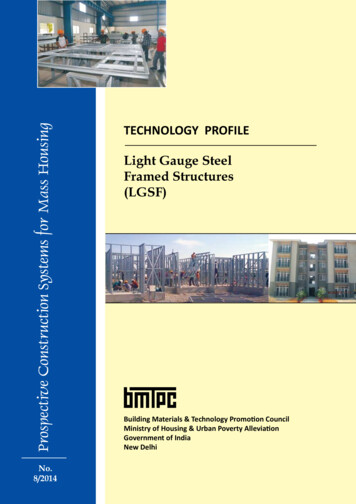
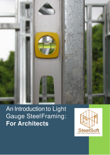
PART1CERTIFICATION1.1Certificate Holder:M/S JB Fabinfra Pvt. Ltd.907, Bhikaji Cama BhawanBhikaji Cama PlaceNew Delhi-110066Phone No. 099582228571.2Description Of System1.2.1Name of the System – Light Gauge Framed Steel Structure1.2.2Brief DescriptionLight Gauge Framed Steel Structure (LGFSS) is based on factory madegalvanized light gauge steel components produced by the cold formingmethod assembled as panels at site forming structural steel framework ofa building and varying wall and floor construction as detailed in thisCertificate. The panels are assembled on site with screws and bolts toform the internal and separating walls and inner leaf of the external wallsof a building and floors & ceiling. The building is completed by theinstallation of an external layer of insulation material and outer leaf of CPBoard or dry mix shotcrete.The system can incorporate all types of architectural features like coving,boxes, cantilevers, projections, infill walls, mezzanine floors etc. Thissystem can also incorporate all types of services viz. electrical, gas andplumbing etc. The design and engineering of the structures is executed byfollowing the norms & guidelines stipulated in relevant Indian Standards.Typical section showing various components of Light Gauge Framed Steelstructure is illustrated in Fig. 1.3
1.2.3Fig. 1Profiles and Sizes of Framing ComponentsThe wall and floor panels are assembled from C section studs on a 610mm grid aligning on centerlines and U section perimeter track ofgalvanized steel of specified grade, thickness and size, conforming toASTM A 653/A, 653/M: 2013, IS277:1992 with minimum coating of Z 275as per the details given below in Tables 1 and 2.Table 1: Stud ProfilesShapeWidth (Web) (mm)STUDThickness of 0.84, 1.2, 1.6 &2mm in required cut size withservice slots, as per design 52.4152.4152.4203.2203.2203.2Flange Height .5
Table 2: Track ProfilesShapeWidth (Web) (mm)TRACKThickness of 0.84, 1.2, 1.6 &2mm in required cut size withservices slots, as per design& requirementFlange Height 9.463.5ANGLE1.3Assessment1.3.11.3.1.1Scope of AssessmentScope of assessment included conformance ofsteel sections to the specified requirements for use as:i)Multistoreyed residential Apartmentsii)Low rise residential buildings1.3.21.3.2.1Basis of AssessmentAssessment of the suitability of the sections manufactured at M/s JBFabinfra, Raigarh as framed structure is based on(i)Inspection of the factory(ii)Inspection of the test equipment used, test procedures followed andtesting personnel involved in the laboratory of the factory(iii)Design details of G 3 two bed room flat considering wind load,seismic load etc. complete duly vetted by IIT Madras(iv)Assessment of quality assurance procedures implemented in thefactory(v)Inspection of different stages of 12 blocks of Staff Quarters atPrasadha, Raigarh and Construction of 2 nd floor extension of Girlshostel of GP Jindal Institute of Technology, Raigarh.1.41.4.1Use of The LGSS And LimitationsThe system shall be used as framed steel structure.5manufactured
1.4.2Limitation of Use1.4.2.11.4.2.2LGSS may be used only upto G 3 level without any compositionLGSS may be used in G 3 and above with composition of hot rolledstructuresLGSS shall not be used for buildings with vibrationsAdvisable span for LGSS buildings shall be up to 6.5m.1.4.2.31.4.2.41.4.3DurabilityThe Certificate Holder shall provide necessary structural warrantyensuring durability of the system to the user, on demand. The windows,doors and internal fittings used on specified projects are outside the scopeof this Certificate and their durability must be assessed independently.1.51.5.1Conditions of CertificationTechnical Conditions1.5.1.1The raw materials and the finished sections shall conform to therequirements of the prescribed specifications.The building to be constructed using Light Gauge Steel Structure shall bedesigned by competent structural engineer in accordance with thespecifications following relevant codal requirements, manufactured as perthe details worked out in design and constructed by trained persons onlywith technical support or supervision by qualified engineers and builders,based on structural designs and seismic evaluation & wind forces as perthe details given in the Construction Manual and this PAC.The structural engineers and building designers associated with such typeof construction should be thoroughly familiar with the various structuralaspects. It is also recommended that Architects and ConstructionEngineers who undertake such building design and construction gainfamiliarity with the properties and materials, characteristics of Light GaugeSteel System and its applications.1.5.1.21.5.1.31.5.2Quality AssuranceThe Certificate Holder shall implement & maintain a quality assurancesystem in accordance with Scheme of Quality Assurance (SQA) given inAnnex A attached with this Certificate. Process Flow (Standard OperatingProcedure) for Light Gauge Steel Structure is also given in Annex B.1.5.31.5.3.1Handling of User ComplaintsThe Certificate holder shall provide quick redressal to consumer/usercomplaints proved reasonable & genuine and within the conditions ofwarranty provided by it to customer/purchaserThe Certificate holder shall implement the procedure included in the SQA.As part of PACS Certification he shall maintain data on such complaints1.5.3.26
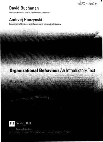
with a view to assess the complaint satisfaction and suitable preventivemeasures taken.1.61.6.1PARTCertificationOn the basis of assessment given in Part 3 of this Certificate & subject tothe conditions of certification, use & limitations set out in this Certificateand if selected, installed & maintained as set out in Part 1 & 2 of thisCertificate, the sections covered by this Certificate are fit for use set out inthe Scope of Assessment.2CERTIFICATE HOLDER’S TECHNICAL SPECIFICATION2.12.1.1GeneralThe PAC holder shall manufacture these sections in accordance with therequirements specified in the relevant Standards. In addition it shall followthe Company standards specifying requirements of various materials usedin the manufacture of these sections (see Part 5)2.22.2.1Specifications for the SystemSpecificationThe manufacturer shall only use the raw materials supplied with therelevant documents as laid down in the prescribed Quality AssurancePlan. The raw materials shall be subject to agreed controls and tests bythe manufacturer before acceptance.2.2.22.2.2.1Technical SpecificationsRaw materials1. Stud & track profiles shall be manufactured from pre-galvanized hightensile steel conforming to IS 277:1992, ASTM A 653/A 653M-2013 Grade350 having Yield stress of min.350 MPa & Tensile stress of min. 380 MPaand coating of min. Z 275 or equivalent as per the Performancerequirement, Dimensions and Permissible tolerances shall to ASTM C:95507. See Fig 2 and table 3(i) Track shall be formed in a U-shaped configuration, having a depthcompatible with that of the studs of the same nominal size.(ii) Min. height of track flanges shall be 19 mm.(iii) Bracing and bridging shall have configuration and steel thickness toprovide secondary support for the studs in accordance with the relevantspecifications for the Design of Cold-formed Steel Structural Members.(iv) Members shall be manufactured within the tolerance limits as shown inFig.2 and Table 1 below(v) The width of the board to which the sheathing board is attached shallnot be less than 32 mm7
Manufacturing TolerancesFig. 1Table 1: Manufacturing TolerancesFig. 2 Manufacturing TolerancesDimensionABCDEFGHITable 3 Manufacturing TolerancesItemStructural StudStructural Track(mm)(mm)Length 2.38 12.7- 6.35-2.38Web width 0.79 0.79- 0.79-3.18Flare overbend 1.59 0-1.59-2.38Holecentre 1.59NA-1.59widthHolecentre 6.35NAlength-6.35Crown 1.59 1.59-1.59-1.59Camber0.790.7912.7 max12.7 maxBow0.790.7912.7 max12.7 maxTwist0.790.7912.7 max12.7 max8
2.2.2.22.2.2.3MS plate shall conform to IS 2062:1999, E250Other components(a) Heavy duty CP Board shall conform to IS 14862:2000(b) Gypsum board shall conform to IS 2095 (Part-1):2011(c) Gunniting/shotcreting(d) shall conform to IS 9012:1978(e) Screws as per the details given below shall be used:(i)Panel Assembly – Low profile screws(ii)LGS-LGS Wall panel to roof cassette – 12-14x15mm(iii)LGS to concrete – Tapcon screw 14-12x60mm Hex head(iv)Wire mesh EPS board – SDS Hexhead with Ceresinwithout washer(v)HRS-LGS – Hex heat(vi)CP board 6mm – WT 8 CSK Phillips(vii) Gypsum board – Flat heat self-driven type(viii) Deck sheet/Wire mesh – SDS WT, CSK, Flat head2.2.2.4Wire mesh – made of 4mm dia wire of UTS 480 MPa of spacing 150x150mm or 1.4mm dia of spacing 40x40mm2.2.2.52.2.2.6Rockwool slab having density 100 kg/m3 shall conform to IS 8183:1993Rockwool roll with Aluminium foil having density 36 kg/m3 shall conform toIS 8183:19932.3Inspections & TestingInspections & testing shall be done at appropriate stages manufacturingprocess. The inspected sections shall be stored & packed to ensure thatno damage occurs during transportation. As part of quality assurance,regular in process inspections shall be carried out by the trained personnelof the PAC holder.Detailed Guidelines for Inspection of Cold-formed Steel StructuralFraming in Low Rise Buildings are given in Annex C.2.42.4.12.4.22.4.3Design ConsiderationThe system is intended for use where Architectural drawings are availableand satisfy the various requirements. The Architect and Engineer designerteam of the concerned developer/ owner (client) is responsible for thedrawings and overall building design to comply with the various regulatoryrequirements applicable to the area. However, design of any structureshall be done based on the details given in Annex D.All installation using light gauge steel structure panels shall be designedby qualified structural engineer, based on the data supplied by theCertificate holder.The design engineer shall liase with the engineer of the developer for9
2.4.4design of the foundation.The design assumptions, detailed calculations, references to necessaryand detailed design drawings shall be made available on demand, ifrequired. The structural design calculations should clearly demonstratestructural integrity and stability including connection details. Designcalculations should have proper sketches annotated in English.2.4.5Foundation shall be specifically designed in accordance with provisiongiven in IS 1904:1986. All foundations should be designed by structuralengineer with appropriate reference.2.4.6In addition, any other requirement regarding safety against earthquakeneed to be ensured by the designer as per prevailing codal requirements.2.5Machinery Involved(i)Four Pinnacle Roll forming machines having capacity upto 3000 m/hrand capability of 25 m/min manufactured in USA(ii)One Vertical Saw machine Felder Kappa V60 having capacity upto 20m/s and capability of 1140 m3/hr2.6Construction ProcessConstruction phases of steel buildings resemble the phases ofconventional reinforced concrete buildings. The building is designed anddetails of sections are worked out. Then the steel frame constructionstarts. The production takes place in the factory as floor, wall and roof etc.components of the building are manufactured as galvanized steel profilesin appropriate sizes. These profiles are sent to the construction sitewithout loss, either as profiles or as panelized parts, considering thedistance of the construction site and transportation conditions. Profiles areassembled by expert assembling teams at the construction site in line withthe architectural plan. Only special studs are used during the assembly,no welding is done. When the assembly is done, the frame is filled withinsulation materials (fiberglass, rock wool etc.). Walls are covered withstandard boards or similar materials.2.72.7.1Unloading & Storage and Marking & IdentificationUnloading and StorageThe panels for each floor shall be unloaded and stacked so that theyare in the necessary sequence for erection. Panels shall be protectedfrom high winds and sharp impact. Panels shall be usually set starting atone corner of the building and proceeding to clockwise fashion. At thetime of unloading:2.7.1.1Before starting erection, it should be made sure that a complete set oferection drawings marked “Good for Construction (GFC)” are availablein the register, which shows all the drawings in the set along with the10
latest revision number and date. All the panels should check with theDispatch Packing List.2.7.1.2If the panel has been damaged through transportation, it should be notedby the engineer in charge.As the material is unloaded, it can be stored conveniently around the site.a)On receipt of material, it should be examined for damage. If asmall amount of moisture is present, the member should be driedbefore restacking or storage. Damp material should never berestacked until thoroughly dry.b)The stud/joist/panel must be properly packaged and stored,otherwise, white rust may develop at minute cracks at the cutedges. When galvanized stud/joist/panel become wet from rain,natural condensation, or other causes, white rust may result. Thismay occur either in transit or in storage at the jobsite.c)Roofing and siding sheets should be erected as soon as possibleafter their arrival at the jobsite. If temporary storage is absolutelynecessary, they should be stored indoors. Where indoor storage isnot possible, entry of moisture into the bundle and consequentstorage stain should be prevented.d)Steel bundles shall be stored level.e)Steel members shall be protected from weather.f)Do not open bundles until time of installation. Care shall be takenwhen handling bundles and individual components to preventinjury to handlers or damage by forklift or crane.g)Twisting of steel members, or applying loads to the memberswhen flat, may damage them.h)Damaged steel members shall not be used.i)Care should be exercised when handling flat steel joist members.Beginning with the unloading process, and throughout all phasesof construction, care must be taken to avoid lateral and torsionalbending (twisting) of members, which may cause damage to thesteel joist members.2.7.22.7.2.1Marking and IdentificationGroups of like members shall be marked with a label or a tag attachedthereto. Marking shall include the manufacturer’s identification (name, logoetc.), length, quantity and manufacturer’s member designator includingdepth, flange size and min. steel thickness.2.7.2.2In addition to the marking reference, individual members shall have alegible label, stencil or embossment at a max. distance of 2.44m on centreon the member with the following minimum information:(i)(ii)The min. steel thickness in mm, exclusive of protective coatingsThe min. yield strength in N/m211
(iii)Where colour coding of members or bundles of like members isemployed, the standard colour coding shall be used.2.8Erection & Fixing Process2.8.1FoundationFoundations to light steel framing are essentially the same as for anyother form of construction, although the dead loads applied by the lightsteel frame will be much lower than in concrete or masonry construction.The foundation line should be matched with GFC drawings.All forms of frame construction require an accurate ‘starting point’.Therefore, the foundations or ground beams must be finished accurately inorder to be acceptable for ‘hand-over’ to the frame erector. For accurateerection of the frame, the following tolerances are provided while in widethe engineering practice (SCI P301)Length of wall frame /- 10 mm in 10 m.Line of wall frame /- 5 mm from outer face of plate.Level of base of wall frame /- 5 mm over complete wall line.a) All tracks should completely rest on foundation to concrete.b) Before doing any fabrication or erection, the engineering departmentwill usually submit fabrication and erection drawings to the architectand obtain approval. After approval, careful site measurements shouldbe taken that any variations from the original plans can be allowed for.c) The level should be maintained for foundation if there any leveldifference erection can be done with insert plate and finally it shouldbe grouted at the site.2.8.2Wall Panels¾ All load bearing studs, including king and jack studs, shall be seated inthe tracks with a maximum of 0.32 mm between the end of the studand the web of the track.¾ Wall bridging shall use the same pattern of blocked bay at the end ofeach run with additional intermediate blocked bays at 3.6 m on centrefor lengths of walls greater than 3.6 m. Wall bridging is not necessary ifappropriate sheathing is placed on both flanges of the stud prior toloading the wall.¾ Adequate temporary wall bracing shall be provided until permanentbracing has been installed. Temporary construction bracing may alsoremain in place after permanent bracing is installed.¾ A sill sealer, or equivalent, shall be provided between the underside ofthe wall when fastened directly to concrete.12
¾ During erection, support may be provided in sufficient number toprevent distortion and damage to frame work due to wind or erectionforces. These cables may also be used to plumb and align the work.¾ All erection work must be level and to dimensions and elevations asindicated by plans, using leveling instruments and plumb bob.¾ Report any discrepancies in plumbing or leveling to engineerin charge.¾ Make certain that, equipment of adequate capacity are available.¾ All the wall lines should be marked in the site.¾ Starting at any convenient external corner stand and plumb a wallframe panel in its exact position.¾ Stand and plumb the adjoining frame to make a self-supportingcorner.¾ Clamp the frames together and check again both the frames are intheir exact locations and standing vertical.¾ Connect the frames using the manufacturers recommended method.¾ Proceed with the erection of the frames around the house, standinginternal and external frames as they occur.¾ Provide adequate temporary bracing during wall frame erection. Theline of top plates in a run of walling should be checked with a string.¾As-built tolerances for light steel framed structuresLight steel framing is very accurate and dimensional variationsare largely due to the inaccuracy of the other components,particularly the foundations. Light steel framing may be used withall foundation types but care must be taken to ensure that targetline and level tolerances are achieved, in order to assemble thewall panels accurately.¾Head of Stud WallOverall HeightPlumb of stud wall:Maximum deviation of /-15mm in overall height of wall (3 storey) or /- 10mm in overall height of wall (2 storey) and /- 5mm in storeyheight (approx. 2.5m)¾Base of stud wallVerticality of frame (relative to base) Temporary bracingWall frames are unstable until floor members are fixed in position.As with any type of building, it is unsafe practice to leave a partiallyerected structure in an unstable state. Therefore, temporary sidesupports or bracing may be required, particularly when thestructure is left overnight in a partially erected condition.The requirements of every individual case should be separatelyconsidered but it may be appropriate to use a scaffold ‘cage’ for13
extra restraint. The addition of other loads, such as stacking ofplasterboard on suspended floors, is not acceptable until theframework has been completed and fully braced. These loadsshould be checked by the designer.2.8.3Floor Panels¾ Follow in-line-framing layout when require¾ Use of string line, plumb bob, level, or transit is encouraged to ensurethat the foundation is relatively “true” before beginning installationbecause tolerances are very critical in achieving an acceptable floor¾ Track members shall not be used individually for any load carryingapplications without an approved design.¾ Bearing surfaces for joists shall be uniform and level.¾ Adequate temporary joist bracing shall be provided until permanentbracing has been installed. Temporary construction bracing may alsoremain in place after permanent bracing is installed.¾ All anchors, hangers, tie-downs, bearing ledgers, etc., that are part ofthe supporting structure shall be properly placed and attached. Nosteel joist shall ever be installed on anchors or ties that havetemporary connections to the supporting structure.¾ Web stiffeners shall be installed at all concentrated load locationsand are often required at bearing points (i.e., where joists bear onbearing walls or beams) unless designed otherwise.¾ Web stiffeners are permitted to be installed on either face of the joistweb.¾ Floor joists shall not be loaded before bracing or sheathing isinstalled. Heavy construction loads, such as stacks of plywood,gypsum board, bricks, etc., shall not be placed on floor joists beforethey are properly braced or without appropriately distributing the loadso the capacity of the floor system is not exceeded.¾ Walking across unbraced floor systems should be avoided. This maycause an unexpected fall.¾ Sub-flooring should be checked for squeaks. Correct as necessary.¾ Allow a small gap on either end of the floor joist to keep the floor joistaway from the rim joist so that the potential problem of the floor joistrubbing against the rim joist and causing squeaks in the floor iseliminated.2.8.4Roof PanelsThe truss system is the most common roof system. The truss spacing isdetermined by the type of roof cladding (i. e. tile or steel sheeting), thestrength and rigidity of the battens and safety guidelines for safeinstallation of cladding. It is possible to increase this spacing if a ‘workmethod statement’ is developed to show it is safe to install battens andcladding on trusses spaced further apart.14
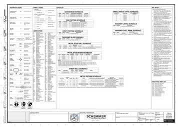
Truss chords typically use one of following sections:¾ Floor or roof trusses shall be engineered by a design professional.¾ Dimensions and proper bearing locations, as shown on truss designdrawing, shall always be verified before starting installation of thetruss.¾ Temporary construction bracing shall remain in place as long asnecessary for the safe and acceptable completion of the roof or floorand may also remain in place after permanent bracing is installed.¾ Trusses are laterally unstable until bracing is properly installed;necessary caution shall be employed during the installation process.Overloading of roof trusses before permanent bracing and/orsheathing is installed is not permitted.¾ Heavy construction loads, such as stacks of plywood, gypsum board,bricks, HVAC units, etc., shall never be placed on trusses before theyare properly braced. Trusses are not typically designed for dynamicloads (moving loads). Sleepers for mechanical equipment shall belocated at panel points or over main supporting members, or ontrusses that have been designed to carry such loads.¾ Any corrections that involve cutting, drilling, or relocation of any trussmember or component shall not be made without notifying the trussmanufacturer of the need for and extent of the modifications. Allmajor corrections, cutting, or drilling of truss members without theapproval of a qualified design professional shall be prohibited.¾ Trusses shall not be placed over loose lintels, shelf angles, headers,beams, or other supporting structures not securely attached to thebuilding.¾ Trusses that do not meet interior load bearing walls shall be shimmedfor adequate bearing.¾ Trusses shall not be pulled down to any interior partition.Table 4 Minimum Allowable Fastener Capacity for Steel to Steel Connections1.2 [Safety factor 3.0]Minimum Capacity (N)ScrewSizeMinimumShankDiameterMinimum HeadDiameterShear CapacityPullout Capacity1.10mm0.84mm1.10mm0.84mmNo. 80.7381.4491098738423324No. 100.8551.7281183796.54903781 Values represent the smaller thickness of two pieces of steel being connected.2. Screw capacities given are calculated in accordance with CCFSS Technical Bulletin [25].2.8.5Decking SheetThickness and profile of decking sheet shall be verified with the erection15
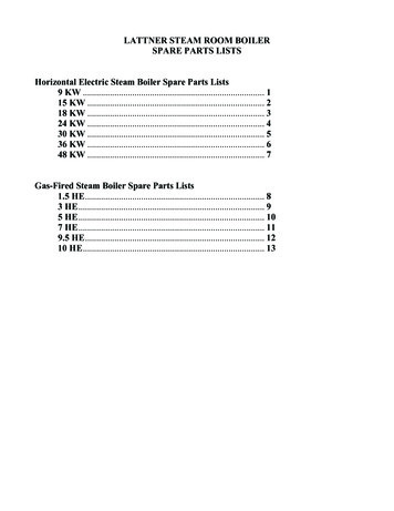
drawings. These are normally used as temporary supports for the concrete tillhardens. Decking sheet has to be screwed to the joist with maximum spacingof 600 mm c/c for uniform action of concrete and joist. All the joints of deckingsheets longitudinal direction requires a minimum lap of 100 mm.2.8.6Finishing of WallWalling materials such as CP board, Gypsum board, Gunniting/shotcreting &PPGI sheet etc. when used for completing the wall internally & externallyshall conform to the relevant Indian Standards as applicable wall. Details offixing of wall panels using these materials as shown in Figs. 11 to 17 ofAnnex E may be referred for guidance.Walling materials used in the system shall be such that the completed wallprovides fire resistant property as per requirements given in NationalBuilding Code 2005.2.8.7Cladding with GI SheetsThickness and profile of sheet shall be verified with the erection drawings.These are normally used as roof/ wall cladding and design to resist windload. Sheet has to be screwed to the joist/ purlin with maximum spacing of300 mm c/c. All the joints of sheets longitudinal direction requires a minimumlap of 150 mm in order to make leak proof. Sealant tape/ sealant paste shallbe used at joints to avoid any type of leakageStructural drawings (Fig. 5 to 27) showing Erection & Fixing details of LGSStructure are appended at Annex E.The erection procedure for a light gauge steel frame used in housing is illustrated inFig. 3Fig. 316
2.8.8M & E ServicesPre-punched service holes in the web of the steel frame allows electrical,gas and plumbing services to be installed within the wall framing system.Plastic grommets and silicone seals shall be used to fasten and protectwiring and pipes from corrosion and damage arising from vibrations.2.8.9Electrical and Plumbing ServicesElectrical and plumbing services are outside the scope of this Certificate;however, in designing and installing these services, precautions must betaken to avoid the possible risk of long term damage to the structure or theservices by e.g. the ingress of water, water vapour or condensation fromwater service pipes.Electrical cables running within the insulation layer in the separating floorconstruction should be protected with cartridge fuses or min circuitbreakers.Where it is necessary for fittings, services or ducts to penetrate a wall orfloor construction, the detailing must ensure that the relevant fireresistance, acoustic performance and water & vapour resistance is notimpaired, particularly in relation to the fire integrity requirements2.9Good Practices for Installation & MaintenanceGood practice as per requirement including Do’s & Don’ts of working withLGSS System of the manufacturer shall be followed for erection andmaintenance of these sections.2.10Maintenance RequirementsIt is assumed that no special maintenance is required during intendedworking life. Should repairs prove necessary, it shall ably be carried out bythe trained persons using appropriate products and materials. Thestructures shall be r
6 1.4.2 Limitation of Use 1.4.2.1 LGSS may be used only upto G 3 level without any composition 1.4.2.2 LGSS may be used in G 3 and above with composition of hot rolled structures 1.4.2.3 LGSS shall not be used for buildings with vibrations 1.4.2.4 Advisable span for LGSS buildings shall be up to 6.5m. 1.4.3 Durability The Certificate Holder shall provide necessary structural warranty