Transcription
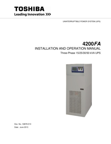
UNINTERRUPTIBLE POWER SYSTEM (UPS)4200FAINSTALLATION AND OPERATION MANUALThree-Phase 15/25/30/50 kVA UPSDoc. No.: 53878-013Date: June 2013
4200FA Installation and Operation Manual
4200FAINSTALLATION AND OPERATION MANUALThree-Phase 15/25/30/50 kVA UPSFOR all 15 – 50 kVA MODELS WITH TOUCHSCREEN INTERFACE:TOSHIBA INTERNATIONAL CORPORATIONINDUSTRIAL DIVISION13131 West Little York RoadHouston, TX 77041-99904200FA Installation and Operation Manual3
Product Use and Warranty RestrictionsThe Toshiba products listed in this document are intended for usage in general electronics applications(computer, personal equipment, office equipment, measuring equipment, industrial robotics, domesticappliances, etc.). These Toshiba products are neither intended nor warranted for usage in equipment thatrequires extraordinarily high quality and/or reliability or where a malfunction or failure may cause loss ofhuman life or bodily injury (Unintended Usage). Unintended Usage includes atomic energy controlinstruments, airplane or spaceship instruments, transportation instruments, traffic signal instruments,combustion control instruments, life-support equipment, all types of safety devices, etc. Unintended Usageof Toshiba products listed in this document shall be made at the customer’s own risk.NOTICEPLEASE INFORM A TOSHIBA INTERNATIONAL CORPORATION REPRESENTATIVE IN CASEOF INCONSISTENCIES, OMISSIONS, OR QUESTIONS.The instructions contained in this manual are not intended to cover all of the details or variations inequipment, or to provide for every possible contingency concerning installation, operation, or maintenance.Should further information be required or if problems arise which are not covered sufficiently, contact yourToshiba sales office.The contents of this instruction manual shall not become a part of or modify any prior or existingagreement, commitment, or relationship. The sales contract contains the entire obligation of ToshibaInternational Corporation UPS Division. The warranty contained in the contract between the parties is thesole warranty of Toshiba International Corporation UPS Division and any statements contained herein DONOT create new warranties or modify the existing warranty.Any electrical or mechanical modifications to this equipment without prior written consent of ToshibaInternational Corporation will void all warranties and may void the UL/CUL listing. Unauthorizedmodifications can also result in personal injury, loss of life, or destruction of the equipment.QUALIFIED PERSONNEL ONLYQualified Personnel are those who have the skills and knowledge relating to the construction, installation,operation, and maintenance of the electrical equipment and have received safety training on the hazardsinvolved (Refer to the latest edition of NFPA 70E for additional safety requirements).4200FA Installation and Operation Manual
UNINTERRUPTIBLE POWER SYSTEMIf additional information or technical assistance is required call TOSHIBACustomer Support Center toll free at 1- 877-867-8773, or write to: ToshibaInternational Corporation, 13131 West Little York Road, Houston, TX 770419990 Attn: UPS Product Manager.Please complete the following information for your records. Unless otherwisespecified on the warranty card, the warranty period for the UPS or UPS part is36 months from the shipment date (see bill of lading).Unless otherwise specified on the warranty card, the warranty period for aUPS battery is 24 months from the shipment date (see bill of lading).Keep this manual with the UPS equipment.Job Number:Model Number:Serial Number:Application:Shipping Date:Date of Installation:Inspected By:4200FA Installation and Operation Manual5
Purpose and Scope of ManualThis manual provides information on how to safely install, operate, and maintain your TOSHIBA powerelectronics product. This manual includes a section on General Safety Instructions that describes thewarning labels and symbols that are used throughout the manual. Read the manual completely beforeinstalling, operating, or performing maintenance on this equipment.This manual and the accompanying drawings should be considered a permanent part of the equipment andshould be readily available for reference and review. Dimensions shown in the manual are in metric and/orthe English equivalent.TOSHIBA reserves the right, without prior notice, to update information, make product changes, or todiscontinue any product or service identified in this publication.TOSHIBA is a registered trademark of TOSHIBA INTERNATIONAL CORPORATION. All other product ortrade references appearing in this manual are registered trademarks of their respective owners.TOSHIBA shall not be liable for technical or editorial omissions or mistakes in this manual. Norshall it be liable for incidental or consequential damages resulting from the use of informationcontained in this manual.This manual is copyrighted. No part of this manual may be photocopied or reproduced in any form withoutthe prior written consent of TOSHIBA INTERNATIONAL CORPORATION. Copyright 2013 TOSHIBA INTERNATIONAL CORPORATION.All rights reserved.Printed in the U.S.A.Contacting TOSHIBA Customer Support CenterThe TOSHIBA Customer Support Center can be contacted to obtain help in resolving any UninterruptiblePower System problem that you may experience or to provide application information.The center is open from 8 a.m. to 5 p.m. (CST), Monday through Friday. The Support Center’s toll freenumber in USA is (877) 867-8773.You may contact TOSHIBA by writing to:TOSHIBA INTERNATIONAL CORPORATION.INDUSTRIAL DIVISION13131 West Little York Rd.Houston, TX 77041-9990Attn: UPS Product Manager4200FA Installation and Operation Manual
TABLE OF CONTENTSTABLE OF CONTENTS . iList of Tables . ivTable of Figures. v1GENERAL SAFETY INSTRUCTIONS . 11.11.2EQUIPMENT WARNING LABELS . 2IMPORTANT SAFETY INSTRUCTIONS . 52INSTRUCTIONS IMPORTANTES CONCERNANT LA SÉCURITÉ . 83Product Description . 93.13.23.33.44Product Unpacking / Inspection / Storage / Disposal .114.14.24.34.44.54.64.74.84.95Unpack the Premium 15/25/30 kVA UPS (with Casters) . 11Unpack the Base and Seismic model 15/25/30 kVA UPS (without Casters) . 12Unpack the Premium 50 kVA UPS (with Casters) . 13Unpack the Base and Seismic 50 kVA UPS (without Casters) . 14Inspect UPS equipment After Unpacking: . 15Permanent Anchoring for Premium 15/25/30/50 kVA UPS (with Casters) . 15Permanent Anchoring for Base and Seismic model 15/25/30/50 kVA UPS (without Casters) . 16Storage of UPS equipment . 17Disposal . 17Installation Precautions . 185.15.25.36Theory of Operation . 9Application and Use . 9Power Backup . 9Power Conditioning . 9Equipment Placement . 18System Preparation (Pre-Power) . 19Operating Precautions . 19UPS Connections. .4.16.56.66.7Power Connections . 20Power Connections 15/25/30 kVA with Internal Batteries . 20Power Connections 15/25/30 kVA with Internal Transformer . 20Recommended Wire Size and Torque Requirements for 15/25/30kVA. 21Power Connection Cable Routing and Conduit Placement 15/25/30 kVA . 24Control Circuit and External Battery Interface Connections 15/25/30 kVA . 25Recommended Wire Size and Torque Requirements . 27Power Connections – 50 kVA . 27Recommended Wire Size and Torque Requirements for 50kVA. 29Power Cable Routing and Conduit Placement 50 kVA . 31Control Circuit and External Interface Connections 50 kVA . 32Recommended Wire Size and Torque Requirements . 34Remote Contact . 35RemotEye III. 36RS-232C . 364200FA Installation and Operation Manuali
6.7.17UPS Shutdown (via RS-232C) . 37Specifications . 387.14200FA 15 / 25 kVA @ 208 VAC Input/ 208 VAC Output - No Internal Batteries or Transformer 387.24200FA 15 / 25 kVA @ 208 VAC Input/ 208 VAC Output w/Internal Batteries . 407.34200FA 15/25 kVA w/Internal Transformer . 427.44200FA 30 kVA @ 208 VAC Input/ 208 VAC Output - No Internal Batteries, No InternalTransformer . 447.54200FA 30 kVA @ 208 VAC Input/ 208 VAC Output w/Internal Batteries . 467.64200FA 30 kVA w/Internal Transformer . 487.74200FA 50kVA @ 208 VAC Input/ 208 VAC Output - No Internal Batteries, No InternalTransformer . 507.84200FA 50kVA @ 208 VAC Input/ 208 VAC Output w/Internal Batteries . 527.94200FA 50kVA w/Internal Transformer . 547.104200FA Efficiencies and Thermal Losses at Various Loads . 557.10.17.10.27.10.37.10.47.10.58Operating the UPS . 578.18.28.38.48.58.68.79AC Input Mode (Normal Operation) . 57Bypass Mode. 58Bypass Mode for Optional Alternate Input Models . 59Battery Backup Mode . 60Battery Backup Time and Discharge Process . 61Battery Low Voltage Tolerances . 61Battery Recharging. 62Operator Interface. 9.149.159.169.17iiEfficiency with No Internal Transformers . 55Efficiency with Input Transformer . 56Thermal Loss in BTU/Hr. with Input Transformer . 56Efficiency with Input and Output Transformer. 56Thermal Loss in BTU/Hr. with Input and Output Transformers . 56Front Panel Display Layout . 63Display LEDs . 63Operator Manual Controls . 64Bypass/Online Switch . 64EPO (Emergency Power Off) Function . 64Display Reset Switch . 65Audible Alarm Functions . 65Touch Screen Display . 67Header Bar . 68Footer Bar . 68Touch Screen Controls . 694200FA Touchscreen Menu Tree . 71Toolbar: Security . 72Toolbar: Buzzer ON/OFF . 72Toolbar: Touch ON/OFF . 72Toolbar: QUICK VIEW ON/OFF . 72MAIN Tab . 74MONITOR Tab . 754200FA Installation and Operation Manual
9.189.199.209.219.229.239.249.2510SETUP Tab . 76Setup: Calibrating the Touchscreen . 79RECORD Tab. 80HELP Tab . 81System Fault Messages . 81System Warning Messages . 83System Mode Messages . 84System Status Messages . 84UPS Operation . 8610.110.210.310.410.510.610.710.810.9Initial UPS Startup . 86Starting the UPS. 86Stopping the UPS . 87EPO (Emergency Power Off) Function . 87Audible Alarm Functions . 88Initial Battery Charge . 89Start-up Procedure . 89Shutdown Procedure . 90Maintenance Bypass Procedure . 9110.9.110.9.210.9.310.1110.1211To safely set the unit in Maintenance Bypass: . 91Switch from UPS to Maintenance Bypass . 91Switch from Maintenance Bypass to UPS . 92Equalize Charge Mode Select. 93Overload Operation . 93UPS Protection System . 9311.111.212System Protection Features . 93System Protection Functions . 94Start-up / Scheduled Maintenance / Part Replacement. 9512.112.212.313Start-up . 95Preventive Maintenance . 95Parts Replacement . 96External Dimensions / Shipping Dimensions / Weights. 9713.1External Dimensions . 9713.1.113.1.213.1.313.1.413.213.3Dimensions – 15/25/30 kVA with Casters. 97Dimensions – 15/25/30 kVA without Casters. 99Dimensions – 50kVA with casters . 100Dimensions – 50kVA without Casters . 101Shipping Dimensions and Weights . 102Cabinet Color . 102APPENDIX A – Seismic Anchorages . 103APPENDIX B – Installation Planning Guides . 107APPENDIX C – 4200 FA Parameter Definitions . 1154200FA Installation and Operation Manualiii
List of TablesTable 1.1 Recommended Over-Current Protection . 5Table 6.1 Cable Size for Different 3P-3W I/O Voltages . 22Table 6.2 Cable Size for 3P-4W I/O Voltages . 22Table 6.3 Cable Size for Ground . 22Table 6.4 Bypass Wire Size . 23Table 6.5 Remote Contacts Assignment . 26Table 6.6 UPS Control and Battery Wiring . 27Table 6.7 50kVA Cabling Sizes . 29Table 6.8 Bypass Cabling Sizes . 29Table 6.9 Battery Cabling - 50kVA . 30Table 6.10 Grounding Cabling - 50kVA . 30Table 6.11 TB-3 Lug Assignment . 33Table 6.12 TB-3 Tightening Torque . 34Table 6.13 RemotEye III Monitored Parameters . 37Table 7.1 Thermal Loss in BTU/Hr. at Load (No Internal Transformers) . 55Table 9.1 LED Behavior Key . 63Table 9.2 AUDIBLE ALARMS . 65Table 9.3 Touch Screen Layout Components (Initial Main Display) . 67Table 9.4 Header Bar Components . 68Table 9.5 Footer Bar Components . 68Table 9.6 Monitor Touch Screen Controls - . 69Table 9.7 Quick Access Toolbar Controls . 70Table 9.8 Quick View Display Layout . 73Table 9.9 MAIN Tab Components . 74Table 9.10 Setup Parameter Categories . 77Table 9.11 Touchscreen KIeypad Identification . 78Table 9.12 RECORD Tab Description . 80Table 9.13 System Fault Messages . 82Table 9.14 System Warning Messages . 83Table 9.15 System Mode Messages . 84Table 9.16 System Status Messages . 84Table 10.1 AUDIBLE ALARMS . 88Table 11.1 Built-in UPS Fault Protection Functions . 94Table 11.2 Fault Alarms . 95Table 13.1 15-30kVA Shipping Dimensions . 102Table 13.2 50kVA Shipping Dimensions . 102Table 13.3 Weight of Premium and Seismic Units . 102Table 13.4 Weight of Base Units . 102iv4200FA Installation and Operation Manual
Table of FiguresFigure 4-1 Offload 50kVA UPS (No Casters) . 14Figure 4-2 Anchoring for 15-30kVA with Casters . 15Figure 4-3 Anchoring for 50kVA with Casters . 16Figure 4-4 Anchoring Pattern for Basic and Seismic 50kVA (C-Channel Feet) . 16Figure 6-1 Power Cabling for 15-30kVA Units with Internal Batteries . 20Figure 6-2 Power Connections 15/25/30 kVA with Internal Transformer . 21Figure 6-3 15030kVA Cable Routing . 24Figure 6-4 15-30kVA Control and Battery Terminals –TB-3 . 25Figure 6-5 Power Terminals - 50kVA . 27Figure 6-6 Terminal Board Locations - 50lVA . 28Figure 6-7 50kVA Cable Routing and Terminal Location . 31Figure 6-8 50kVA External Interface Assign
4200FA Installation and Operation Manual 3 4200FA INSTALLATION AND OPERATION MANUAL Three-Phase 15/25/30/50 kVA UPS . FOR all 15 - 50 kVA MODELS WITH TOUCHSCREEN INTERFACE: . of Toshiba products listed in this document shall be made at the customer's own risk. NOTICE.