Transcription
632Framing
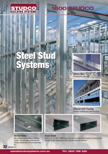
64General RequirementsThe choice and installation of framing depends on a number of factors.In the case of wood framing these include the species, size and gradeof lumber used. In the case of steel framing, the cross-sectional shapeof the frame member, size and the thickness and grade of steel mustbe considered. Equally important are height of the wall, the framespacing and the maximum span of the surfacing material. Selection ofsteel stud size is usually derived from limiting height tables, based onthe capacity of the steel and the allowable deflection of finish surfaces.The limiting heights tables included in the Gypsum ConstructionHandbook are from ASTM C754 and were developed by the GypsumAssociation. CGC presents these data as a reference, but is notresponsible for performance of the wall based on them.TipFor instructions onsafety in the applicationof framing, seeChapter 13.Loads Framing members and their installation must be selected accordingto their ability to withstand the loads to which they will be subjected. Theseinclude live loads (contributed by the occupancy and elements such aswind, snow and earthquake) and dead loads (weight of the structure itself).Minimum lateral load for interior partitions is 240 Pa (5 psf); for exteriorwalls 720 Pa (15 psf) to 2160 Pa (45 psf) or greater depending on buildingheight and geographic location.Deflection Even though an assembly is structurally capable of withstanding a given load, its use may be restricted if the amount of deflection that would occur when the lateral load is applied exceeds thatwhich the surfacing materials can sustain without damage. Obviously,this deflection factor influences the selection of surfacing materials.For drywall assemblies it is desirable to limit deflection to L/240 (L length of the span) and to never exceed L/120 (L/180 in some codes).The preferred limit for veneer assemblies is L/360 and should notexceed L/240. Using L/240 as an example, and where the length of aspan (distance between supports) is 3 metres, deflection is determinedas follows:deflected shapeLoad12.5 mm3000 mmLD Deflection Limit 240L 3 m or 3000 mm3000D D 24012.5 mm
Framing65Bending Stress Framing members also must withstand any unit forceexerted that will break or buckle the stud, based on the capacity of thestuds acting alone.End Reaction Shear This factor is determined by the amount of forceapplied to the stud which will bend or shear the runner, or buckle theweb of the stud.Frame Spacing A factor in load-carrying capability and deflection, italso is a limiting factor for the finishing materials. Every finishing orsurfacing material is subject to a span limitation—the maximum distance between frame members that a material can span without unduesagging. For that reason, “maximum frame spacing” tables for the various board products are included in this chapter. However, where framespacing exceeds maximum limits, furring members can be installed toprovide necessary sag resistance support for the surfacing material(covered in this chapter under wall and ceiling furring).Insulation and Services Chase walls provide vertical shafts wheregreater core widths are needed for pipe runs and other service installations. They consist of a double row of studs with gypsum panel ormetal cross braces between rows. Plumbing, electrical and other fixtures, and mechanicals within the framing cavities must be flush withor inside the plane of the framing. Fasteners used to assemble theframing must be driven reasonably flush with the surfaces.In wood frame construction, the flanges of batt-type insulation must beattached to the sides of frame members and not to their faces. Anyobstruction on the face of frame members that will prevent firm contact between the gypsum board and framing can result in loose ordamaged board and fastener imperfections.Wood FramingWood framing meeting the following minimum requirements is necessary for proper performance of all gypsum drywall and plaster baseassemblies:1. Framework should meet the minimum requirements of applicablebuilding codes.2. Framing members should be straight, true and of uniform dimension.Studs and joists must be in true alignment; bridging, fire stops, soilpipes, etc., must not protrude beyond framing.3. All framing lumber should be the correct grade for the intended use,and 38 mm x 89 mm (nominal 2 x 4) or larger should bear the grademark of a recognized inspection agency.4. All framing lumber should have a moisture content not in excess of19% at time of gypsum board application.Failure to observe these minimum framing requirements, which are applicable to screw, nail and adhesive attachment, will substantially increase thepossibility of fastener failure and surface distortion due to warping ordimensional changes. This is particularly true if the framing lumber hasgreater than normal tendencies to warp or shrink after erection.2
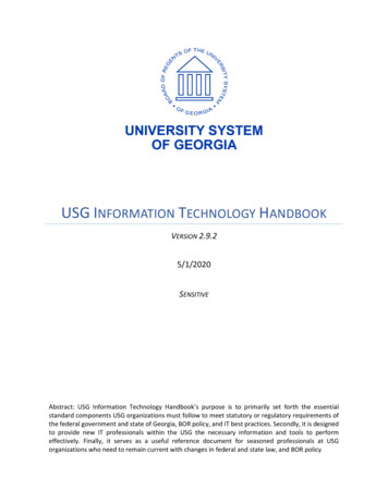
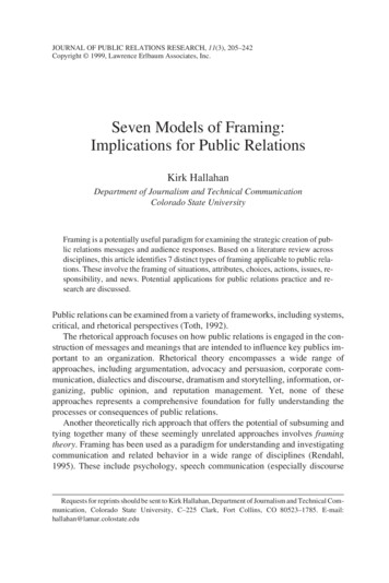
66The moisture content of wood framing should be allowed to adjust asclosely as possible to the level it will reach in service before gypsumdrywall or plaster base application begins. After the building isenclosed, delay board application as long as possible (consistent withschedule requirements) to allow this moisture content adjustment totake place.Framing should be designed to accommodate shrinkage in widedimensional lumber such as is used for floor joists or headers. Gypsumwallboard and veneer plaster surfaces can buckle or crack if firmlyanchored across the flat grain of these wide wood members as shrinkageoccurs. With high uninterrupted walls, such as are a part of cathedralceiling designs or in two-story stairwells, regular or modified balloonframing can minimize the problem.Framing Corrections If joists are out of alignment, 38 mm x 140 mm (2 x 6)leveling plates attached perpendicular to and across top of ceiling joists maybe used. Toe-nailing into joists pulls framing into true horizontal alignmentand ensures a smooth, level ceiling surface. Bowed or warped studs innon-load bearing partitions may be straightened by sawing the hollow sidesat the middle of the bow and driving a wedge into the saw kerf until the studis in line. Reinforcement of the stud is accomplished by securely nailing19 mm x 89 mm (1 x 4) wood strips or “scabs” on each side of the cut.bowed orwarped studsaw kerfFraming MemberSpacingscab nailedto studwedgeTo assure adequate support for gypsum panels, and the integrity ofwalls and ceilings, attention must be paid to the distance betweenframing members. Minimum spacing requirements will depend on anumber of variables, including the location of the paneled surface (ceiling or wall), the thickness of the gypsum panels, the number of panellayers on each side of the completed wall, and the orientation of thepanels to the framing members. For thicker gypsum panels or doublelayer applications, the distance between framing members can beincreased. For wood framing installed in the conventional manner, withlumber meeting requirements outlined above, maximum frame spacingis as shown in the tables on the following pages:
67FramingMaximum Frame Spacing—Drywall ConstructionDirect ApplicationPanel thickness(1)LocationApplication method(2)Max. frame spacing o.c.Single-Layer Application9.5 mm(3/8 4)perpendicularceilings(6)parallel(4)parallel or 00400600161624(5)(6)16241624sidewallsparallel or perpendicular6002412.7 mm(1/2 )sidewalls15.9 mm(5/8 )Double-Layer Application9.5 mm(3/8 )12.7 & 15.9 mm(1/2 & 5/8 pendicular or parallelperpendicular or 4(8)(1) 15.9 mm (5/8 ) thickness is recommended for the finest single-layer construction, providing increased resistance to fire and transmission ofsound; 12.7 mm (1/2 ) for single-layer application in new residential construction and remodeling; and 9.5 mm (3/8 ) for repair and remodeling overexisting surfaces. (2) Long edge position relative to framing. (3) Not recommended below unheated spaces. (4) Not recommended if water-basedtexturing material is to be applied. (5) Max. spacing 400 mm (16 ) if water-based texturing material is to be applied. (6) If 12.7 mm (1/2 ) SHEETROCKBrand Interior Ceiling Board is used in place of gypsum panels, max. spacing is 600 mm (24 ) o.c. for perpendicular application with weight of unsupported insulation not exceeding 6.5 kg/m2 (1.3 psf.), 400 mm (16 ) o.c. with weight of unsupported insulation not exceeding 11 kg/m2 (2.2 psf.)(7) Adhesive must be used to laminate 9.5 mm (3/8 ) board for double-layer ceilings. (8) Max spacing 400 mm (16 ) o.c. if fire rating required.Maximum Frame Spacing—Veneer Plaster ConstructionDirect ApplicationGypsum basethicknessConstruction12.7 mm(1/2 )one layer,1-coat finishApplicationmethod(1)Max. frame spacing perpendicular or parallelperpendicularsidewallstwo layer,ceilings1 & 2-coat finish sidewallsone layer,ceilings1-coat finishsidewallsperpendicular or parallelperpendicular40016400 or 600(2) 16 or 24(2)400 or 600(2)) 16 or 24(2)60024one layer,2-coat finish15.9 mm(5/8 )Locationone layer,2-coat finishceilingssidewallstwo layer,ceilings1 & 2-coat finish sidewallsperpendicular or parallelperpendicular16perpendicular or parallelperpendicular60024400 or 600(2) 16 or 24(2)400 or 600(2) 16 or 24(2)600(2))24(2)24(2)600(2))60024perpendicular or parallel600perpendicular or parallelperpendicular24(1) Perpendicular preferred on all applications for maximum strength. Where fire rating is involved, application must be identical to that in assemblytested. Parallel application not recommended for ceilings. (2) 600 mm (24 ) o.c. frame spacing with either one or two-coat veneer applicationrequires CGC Brand Joint Tape Reinforcement and DURABOND or SHEETROCK Brand Setting-Type Joint Compound.Ceiling Insulation To prevent objectionable sag in ceilings, weight ofoverlaid unsupported insulation should not exceed 6.5 kg/m2 (1.3 psf)for 12.7 mm (1/2 ) thick panels with frame spacing 600 mm (24 ) o.c.;11 kg/m2 (2.2 psf) for 12.7 mm (1/2 ) panels on 400 mm (16 ) o.c.framing and 15.9 mm (5/8 ) panels 600 mm (24 ) o.c.; 9.5 mm (3/8 )thick panels must not be overlaid with unsupported insulation. A vaporretarder should be installed in all exterior ceilings, and the plenum orattic space properly vented.2
68Resilient Application On ceiling assemblies of both drywall and veneerplaster, install resilient channels perpendicular to framing and spaced600 mm (24 ) o.c. for joists 400 mm (16 ) o.c.; 400 mm (16 ) o.c. forjoists 600 mm (24 ) o.c. For sidewalls, install at 600 mm (24 ) o.c. max.See single-layer sections in tables, preceding pages, for limitations forspecific board thickness. Fasten channels to framing with screws only.Cable Heat Ceilings Maximum frame spacing is 400 mm (16 ) o.c. for12.7 mm (1/2 ) IMPERIAL Brand Gypsum Base; 600 mm (24 ) o.c. for15.9 mm (5/8 ) base.Spray-Textured Ceilings Where water-based texturing materials or anyslow-drying surface treatment are used over single-layer panels, max. framespacing is 400 mm (16 ) o.c. for 12.7 mm (1/2 ) panels appliedperpendicular to framing. Parallel application is not recommended, nor is useof 9.5 mm (3/8 ) thick panels. For best results use SHEETROCK Brand InteriorCeiling Board, Sag-Resistant, with max. spacing 600 mm (24 ) o.c. Note:Airless spraying of latex paint in one heavy application 0.25 to 0.36 mm (10to 14 mil) also will sag ceilings. See “Ceiling Sag Precautions” in Chapter 10.Water-based texturing materials applied to ceilings should be completely dry before insulation and vapor retarder are installed. Undermost conditions, drying takes several days.PartitionLayoutProperly position partitions according to layout. Snap chalk lines atceiling and floor. Be certain that partitions will be plumb. Where partitionsoccur parallel to and between joists, ladder blocking must be installedbetween ceiling joists. Double joists are recommended beneath partitions.Steel FramingSteel stud framing for non-load bearing interior partitions is secured tofloors and ceilings with runners fastened to the supporting structure.RunnerInstallationSecurely attach runners:1. To concrete and masonry use stub nails, power-driven fasteners.2. To foam-backed metal (max. 14-ga.) concrete inserts use 9.5 mm(3/8 ) TYPE S-12 Pan Head Screws.3. To suspended ceilings use expandable hollow wall anchors, togglebolts, screws or other suitable fasteners.4. To wood framing use 32 mm (1-1/4 ) TYPE S Oval Head Screws or 8d nails.Fastening channel runnersTo all substrates, secure runners with fasteners located 51 mm (2 )from each end and spaced max. 600 mm (24 ) o.c. (Tall walls requirethat fasteners be spaced closer together. Contact your local sales officefor more detailed information.) Attach runner ends at door frames withtwo anchors when 3-piece frames are used. (One-piece frames shouldbe supplied with welded-in-place floor anchor plates, pre-punched fortwo anchors into structure.)At partition corners, extend one runner to the end of the corner andbutt the other runner to it. Runners should not be mitered.Fastening angles
Framing69Interior Framing Limiting HeightsStudSpacingDesignLimitStud Depth mm (in.)mm in.Pa psf41 mm (1-5/8) (162S125-18/33)41 mm (1-5/8) (162S125-18/33)41 mm (1-5/8) (162S125-18/33)41 mm (1-5/8) (162S125-18/33)41 mm (1-5/8) (162S125-18/33)41 mm (1-5/8) (162S125-18/33)64 mm (2-1/2) (250S125-18/33)64 mm (2-1/2) (250S125-18/33)64 mm (2-1/2) (250S125-18/33)64 mm (2-1/2) (250S125-18/33)64 mm (2-1/2) (250S125-18/33)64 mm (2-1/2) (250S125-18/33)92 mm (3-5/8) (362S125-18/33)92 mm (3-5/8) (362S125-18/33)92 mm (3-5/8) (362S125-18/33)92 mm (3-5/8) (362S125-18/33)92 mm (3-5/8) (362S125-18/33)92 mm (3-5/8) (362S125-18/33)102 mm (4) (400S125-18/33)102 mm (4) (400S125-18/33)102 mm (4) (400S125-18/33)102 mm (4) (400S125-18/33)102 mm (4) (400S125-18/33)102 mm (4) (400S125-18/33)152 mm (6) (600S125-18/33)152 mm (6) (600S125-18/33)152 mm (6) (600S125-18/33)152 mm (6) (600S125-18/33)152 mm (6) (600S125-18/33)152 mm (6) 6161655555555555555555555555555555520 Gauge (33 mil)Allowable 25 Gauge (18 mil)Deflection 0.455 mm min.(0.01799 min. ) 0.836 mm min.(0.03299 min. 0)(30-10)(24-6)(21-4)Notes: The number following the stud depth is a new industry-wide product identification, created by the Steel Stud ManufacturersAssociation; (U.S.) the number identifies the member depth, style, flange width and material thickness in mils.This limiting heights data is from ASTM C754. CGC presents this information only as a reference, and will not be responsible for the performance of walls based on this table. Consult current information from ASTM C754 and SSMA (Steel Stud Manufacturers Association),and the stud manufacturers for limiting heights characteristics of their particular products.Limiting heights apply to walls constructed with minimum 12.7 mm (1/2 ) thickness of gypsum board and with a minimum of one fullheight layer on both sides of the stud framing.Limiting heights are based on tests conducted with gypsum board attached with screws spaced 300 mm (12 ) o.c. to framing members.StudInstallationInsert floor-to-ceiling steel studs between runners, twisting them intoposition. Position studs vertically, with open side facing in same direction,engaging floor and ceiling runners and spaced 400 mm (16 ) or 600 (24 )o.c. max. as required. Proper alignment will provide for proper bracing, utility runs and prevention of stepped or uneven joint surfaces. The recommended practice for most installations is to anchor only those studs adjacent to door and borrowed light frames. This would also be applicable to2
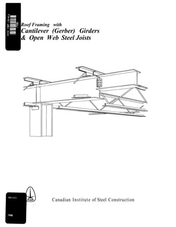
70Steel studs are positioned infloor and ceiling runners.Splicing of steel studs.partition intersections and corners. In cases where a significant slablive load deflection must be accommodated, the anchoring of thesestuds may restrict slab movement and cause partition cracking. Inthese cases, anchoring of these studs may need to be omitted. Theservices of a design professional is desirable to identify theseinstances and address them on a case-specific basis.Place studs in direct contact with all door frame jambs, abutting partitions, partition corners and existing construction elements. Spot grouting of door frames is always suggested and is required where heavy oroversize doors are used. Contact door frame manufacturer for specificrequirements and recommendations.Where a stud directly abuts an exterior wall and there is a possibility ofcondensation or water penetration through the wall, place a No. 15asphalt felt strip between stud and wall surface.Over metal doors and borrowed light frames, place a section of runnerhorizontally with a web-flange bent at each end. Secure runner tostrut-studs with two screws in each bent web. At the location of verticaljoints over the door frame header, position a cut-to-length studextending to the ceiling runner. (See section ‘Door and WindowOpenings’ later in this chapter.)Steel studs may be conveniently spliced together when required. Tosplice two studs, nest one into the other forming a box section, to adepth of at least 200 mm (8 ).Fasten together with two 10 mm (3/8 ) TYPE S Pan Head Screws ineach flange. Locate each screw (shown above) no more than 25 mm(1 ) from ends of splice.Resilient Channel Framing—Steel FramingStud System Installation Attach steel runners at floor and ceiling tostructural elements with suitable fasteners located 50 mm (2 ) from eachend and spaced 600 mm (24 ) o.c. Position studs vertically, with open sidefacing in same direction, engaging floor and ceiling runners, and spaced600 mm (24 ) o.c. For non-fire rated resilient channel system, anchorstuds to floor and ceiling runners on the resilient side of the partition.Fasten runner to stud flange with 10 mm (3/8 ) TYPE S Pan Head Screw.
71FramingResilient Channel Installation Position resilient channel at right anglesto steel studs, space 600 mm (24 ) o.c. and attach to stud flanges with10 mm (3/8 ) TYPE S Pan Head Screws driven through holes in channelmounting flange. Install channels with mounting flange down, except atfloor to accommodate attachment. A strip of gypsum panel is sometimesused at the base of a partition in lieu of the first inverted resilient channel.Locate channels 50 mm (2 ) from floor and within 150 mm (6 ) of ceiling.Splice channel by nesting directly over the stud, screw-attach throughboth flanges. Reinforce with screws located at both ends of the splice.Chase Wall FramingAlign two parallel rows of floor and ceiling runners according to partitionlayout. Spacing between outside flanges of each pair of runners must notexceed 600 mm (24 ). Follow instructions above for attaching runners.Position steel studs vertically in runners, with flanges in the same direction,and with studs on opposite sides of chase directly across from each other.Except in fire-rated walls, anchor all studs to floor and ceiling runnerflanges with 10 mm (3/8 ) or 13 mm (1/2 ) TYPE S Pan Head Screws.Cut cross-bracing to be placed between rows of studs from gypsumboard 300 mm (12 ) high by chase wall width. Space braces 1220 mm(48 ) o.c. vertically and attach to stud web with screws spaced 200 mm(8 ) o.c. max. per brace.Bracing of 64 mm (2-1/2 ) min. steel studs may be used in place ofgypsum board. Anchor web at each end of metal brace to stud web withtwo 10 mm (3/8 ) pan head screws. When chase wall studs are notopposite, install steel stud cross-braces 600 mm (24 ) o.c. horizontally,and securely anchor each end to a continuous horizontal 64 mm (2-1/2 )runner screw-attached to chase wall studs within the cavity.Methods of cross bracing25 mm (1" )TYPE S screwsteel studsteel stud600 mm(24") max.12.7 or 15.9 mm(1/2" or 5/8" )gypsum panelcross brace300 mm (12" ) x widthscrew attachedGypsum braceTwo10 mm (3/8" )TYPE S panhead screwSteel stud brace64 mm (21/2" )steel studcross bracesteelstud64 mm(21/2" )steel studcross brace10 mm (3/8" )TYPE S panheadscrew64 mm (21/2" )steel runnerSteel stud & runner braceDrywall and Plaster Ceiling Suspension SystemsSpace metal furring channels 600 mm (24 ) o.c. at right angles to barjoists or other structural members. As an alternate, 41 mm (1-5/8 ) steelstuds may be used as furring. Saddle-tie furring channels to bar joists withtriple-strand 1.2 mm (18-ga.) tie wire at each intersection. Provide 25 mm(1 ) clearance between furring ends and abutting walls and partitions. Atsplices, nest furring channels with at least an 200 mm (8 ) overlap andsecurely wire-tie each end with triple-strand 1.2 mm (18-ga.) tie wire (seeillustration). Frame around openings such as light troffers with additionalfurring channels and wire-tie to bar joists.2
72Max. allowable spacing for metal furring channel is 600 mm (24 ) o.c.for 12.7 mm (1/2 ) and 15.9 mm (5/8 ) thick gypsum panels or plasterbase. See frame spacing tables for limiting spans.For bar joist spacing up to 1500 mm (60 ), steel studs may be used asfurring channels. Wire-tie studs to supporting framing as shown.Position 41 mm (1-5/8 ) studs with open side up; position larger studswith opening to side. See table for stud spacings and limiting spans.Limiting Span(1)—Metal Furring Members(2)Type furring memberDWC-25-ga.DWC-20-ga.41 mm (1-5/8 ) stud, 25-ga.Single layer panelsDouble layer panels12 kg/m2 (2.5 psf max.)24 kg/m2 (5.0 psf max.)Member spacingmm in. o.c.1-span3-span1-span3-span4006004006004006001750 mm (5 9 )1520 mm (5 0 )2110 mm (6 11 )1830 mm (6 0 )2180 mm (7 2 )1910 mm (6 3 )2160 mm (7 1 )1880 mm (6 2 )2590 mm (8 6 )2260 mm (7 5 )2690 mm (8 10 )2360 mm (7 9 )1400 mm (4 7 )1220 mm (4 0 )1650 mm (5 5 )1450 mm (4 9 )1730 mm (5 8 )1520 mm (5 0 )1730 mm (5 8 )1500 mm (4 11 )2060 mm (6 9 )1800 mm (5 11 )2130 mm (7 0 )1880 mm (6 2 )162416241624(1) For beams, joists, purlins, sub-purlins; not including 38 mm (1-1/2 ) cold rolled channel support spaced 1220 mm (4’0 ) max. Check Manufacturer’sliterature to verify that the selected furring member is capable of the indicated span. (2) Limiting spans for 12.7 mm (1/2 ) and 15.9 mm (5/8 ) thickpanels, max. L/240 deflection and uniform load shown. Investigate concentrated loads such as light fixtures and exhaust fans separately.Metal furring channeltypical hangerspacing1200 mm(4 ) o.c.max.38 mm (1-1/2 ) channel1200 mm (4 ) o.c. max.metal furring channel clip(non-fire rated only)or tie wiremax. spacing600 mm (24 ) o.c.12.7 or 15.9 mm (1/2” or 5/8”)GRAND PRIX Plaster base or SHEETROCKBrand gypsum panels regular orfoil-back max. spacing 400 mm(16 ) or 600 mm (24 ) o.c.
Framing73Steel stud furring38 mm (1-1/2”) channel1220 mm (4 ) o.c. max.hanger spacing1220 mm (4 ) o.c. max.wire tie for fire-ratedconstructionmax. spacing600 mm (24 ) o.c.GRAND PRIX Plaster base orSHEETROCK Brand gypsumpanels regular or foil-backControl jointgypsum panelzinc control jointno. 093SHEETROCK Brandjoint compoundSuspendedCeiling GrillageErectionSpace 4.1 mm (8-ga.) hanger wires 1220 mm (48 ) o.c. along carryingchannels and within 150 mm (6 ) of ends of carrying-channel runs. Inconcrete, anchor hangers by attachment to reinforcing steel, by loopsembedded at least 50 mm (2 ) or by approved inserts. For steelconstruction, wrap hanger around or through beams or joists. Do notattach components to air ducts.Install 38 mm (1-1/2 ) carrying channels 1220 mm (48 ) o.c. (spaced astested for fire-rated construction) and within 150 mm (6 ) of walls.Position channels for proper ceiling height, level and secure with hangerwire saddle tied along channels (see illustration). Provide 25 mm (1 )clearance between runners and abutting walls and partitions. At channelsplices, interlock flanges, overlap ends 300 mm (12 ) and secure eachend with double-strand 1.2 mm (18-ga.) tie wire.Erect metal furring channels at right angles to 38 mm (1-1/2 ) carryingchannels. Space furring within 150 mm (6 ) of walls. Provide 25 mm(1 ) clearance between furring ends and abutting walls and partitions.Attach furring channels to 38 mm (1-1/2 ) channels with wire ties or2
74Steel stud framing systemcross bracing 1220 mm(48") o.c.boxed stud at hanger300 mm (12") long12.7 or 15.9 mm (1/2" or 5/8")GRAND PRIX Plaster base orSHEETROCK Brand gypsum panelsregular or foil-backLighting fixturecross reinforcingas requiredmetal furringchannellight trofferwire tiegypsum base andveneer plasterfurring channel clips installed on alternate sides of carrying channel.Saddle tie furring to channels with double-strand 1.2 mm (18-ga.) tiewire when clips cannot be alternated. At splices, nest furring channelswith at least an 200 mm (8 ) overlap and securely wire tie each endwith double-strand 1.2 mm (18-ga.) tie wire.Where required, in fire-rated assemblies, install double furring channels tosupport gypsum panel ends and back block with gypsum board strip.When staggered end joints are not required, control joints may be used.At light troffers or any openings that interrupt the carrying or furringchannels, install additional cross-reinforcing to restore the lateralstability of grillage.
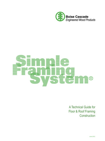
75FramingSingle spanDouble spanTriple spanLimiting Span-Steel Stud Ceiling System (1)StudSingle Span (mm)Spacing (uniform load-Pa)Stud Style64 mm25-ga.92 mm(2)25-ga.102 mm(2) 25-ga.64 mm20-ga.92 mm20-ga.102 mm20-ga.152 602970513042203100StudSingle Span (ft.-in.)Spacing (uniform load-psf)Stud Style2-1/2 25-ga.3-5/8 (2)25-ga.4 (2)25-ga.2-1/2 20-ga.3-5/8 20-ga.4 20-ga.6 20-ga.2Double and Triple Span (mm)(uniform load-Pa)Double and Triple Span (ft.-in.)(uniform 2412162412162412162410 11 9 11 8 8 14 7 13 3 11 7 15 9 14 4 12 6 13 2 11 11 10 5 17 6 15 11 13 11 19 0 17 3 15 0 26 3 23 10 20 10 8 8 7 11 6 9 11 7 10 6 7 3 12 6 11 0 9 0 10 5 9 6 8 3 13 11 12 8 11 0 15 0 13 8 11 11 20 10 18 11 16 6 7 7 6 10 4 9 9 8 7 3 4 9 10 4 9 0 6 8 9 1 8 3 7 3 12 2 11 0 9 8 13 2 11 11 10 4 18 2 16 6 13 11 6 9 5 4 —7 3 5 5 —9 0 7 6 5 0 8 3 7 6 6 4 11 0 10 0 8 4 11 11 10 10 9 0 16 6 14 9 12 0 13 6 12 4 10 2 17 5 14 8 11 2 17 6 14 7 11 0 16 4 14 10 12 11 21 9 19 9 17 8 23 6 21 4 18 8 32 6 29 6 25 9 10 2 8 8 6 11 11 2 9 2 6 8 11 0 8 9 6 3 12 11 11 9 10 1 17 3 15 8 13 3 18 8 16 11 14 3 25 9 21 10 16 10 8 2 6 11 5 9 8 4 6 8 4 9 8 0 6 3 4 4 11 4 10 0 8 2 15 0 13 3 10 10 16 3 14 3 11 7 20 3 16 10 13 10 6 11 5 9 4 4 6 8 5 3 —6 3 4 10 —10 0 8 9 7 1 13 3 11 6 9 4 14 3 12 4 9 9 16 10 13 10 10 2 (1) Based on L/240 allowable deflection. Bracing of top flanges is required and must not exceed 1220 mm (48 ) o.c. Check manufacturer sliterature to verify that the selected framing member is capable of the indicated span. (2) Stud end stiffening required. Additional hangersare necessary when span area exceeds 1.5 m2 (16 ft.2)
76Light Fixture Protection Use over recessed lighting fixtures installed indirect suspension grid when required in fire-rated construction. Cut piecesof 12.7 mm (1/2 ) or 15.9 mm (5/8 ) SHEETROCK Brand Gypsum Panels orGRAND PRIX Plaster Base with FIRECODE C Core to form a five-sided enclosure, trapezoidal in cross-section (see detail). Fabricate box larger than thefixture to provide at least 13 mm (1/2 ) clearance between the box and thefixture, and in accordance with fire test report.Light fixture fire protectiongypsum panelsmain teenails 150 mm(6" ) o.c.cross furringchannelcross teeLighting fixturegypsum panelfixture protectionlight fixture25 mm (1" )TYPES-12 screwsNo. 200 metal trimCGC DrywallSuspension SystemFlat CeilingsMain tees shall be spaced a maximum of 1220 mm (48 ) on center and supportedby hanger wires spaced a maximum 1220 mm (48 ) on center and asspecified by ULC/UL Fire Resistance Directory, attaching hanger wiresdirectly to structure above. Cross tees shall be spaced per manufacturers’recommendations and as specified by ULC or UL Fire Resistance Directory.Curved Ceilings Valley and Vault main tees shall be spaced a maximum 1220 mm (48 ).Hanger wires shall be spaced a maximum 1220 mm (48 ) for Vaultmain tees. Hanger wires shall be spaced a maximum 600 mm (24 ) forValley main tees. Cross tees shall be spaced as per manufacturers’recommendations.
Maximum Frame Spacing—Drywall Construction Direct Application Panel thickness(1) Location Application method(2) Max. frame spacing o.c. Single-Layer Application mm in. 9.5 mm ceilings(3) perpendicular(4) 400 16 (3/8 ) parallel(4) 400 16 12.7 mm ceilings perpendicular 600 24(5)(6) (1/2 ) parallel(4) 400 16 sidewalls parallel or perpendicular 600 24