Transcription
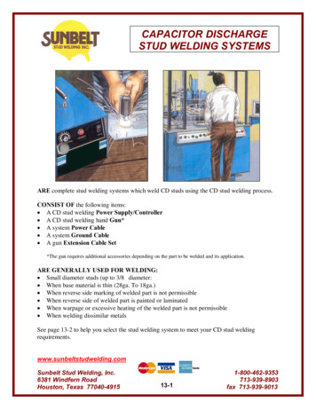
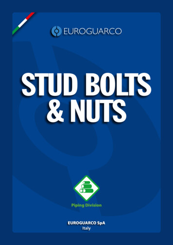
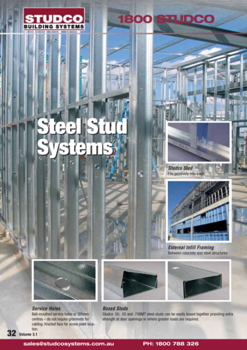
1800 STUDCOSteel StudSystemsStudco StudFits positively into trackExternal Infill FramingBetween concrete and steel structuresService Holes32Bell-mouthed service holes at 500mmcentres – do not require grommets forcabling. Knurled face for screw point location.Volume 3.1Boxed StudsStudco .50, .55 and .75BMT steel studs can be easily boxed together providing extrastrength at door openings or where greater loads are required.sales@studcosystems.com.auPH: 1800 788 326
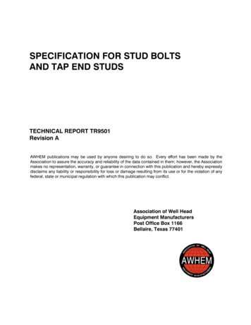
1800 STUDCOSteel Stud SystemsComponentsStud and Track SectionsTable 44LIPPED WALL STUDS - PART NUMBERSBase Metal Thickness - BMTSection Width"a"0.5mm 0.55mm0.75mm1.15mmLipped Wall 115S92115S15012Steel Stud SystemsThe Studco steel stud framing system is engineered to provide designers and installers the solution to createframing systems that are not only durable and versatile but can also achieve the needs and design criteria inaccordance with the BCA and appropriate Australian standards. The Studco steel stud framing system ismanufactured in a range of various widths, lengths and material gauges from 0.50mmBMT to 1.5mm BMT. Thisrange of stud and track profiles not only offer greater span and performance, but also are accompanied by a rangeof accessories including noggings, nogging track and bracket joining systems. The design tables in this sectionhave been formulated to comply with the relevant Australian standards, accompanied by substantial laboratoryand field testing. Construction of fire-rated or sound rated wall systems can be achieved by using the Studco steelframing system and accessories. Refer to the building board manufacturers for more detailed information.Table 45aSTANDARD TRACK - PART NUMBERSBase Metal Thickness - BMTSection Width"a"0.5mm 0.5mm Hemmed 0.55mm 0.7 Hemmed 0.75mm 1.15mm35mmStandard 115T92115T15012Table 46DEFLECTION HEAD TRACK - PART NUMBERS32mmBase Metal Thickness - BMTSection Width"a"0.5mm 0.55mm 0.7mm hemmed 0.75mm51mm64mm76mm92mm150mmaDeflection 15mmN/ADT64115DT76115DT92115DT15012Table 47NOGGING TRACK - PART NUMBERS50mmBase Metal Thickness - BMTSection Width Nogging Track"a"Centres0.5mm 0.55mm0.75mm1.15mmaNogging Track32mmPH: 1800 788 com.au33
1800 STUDCOSteel Stud Systems – ComponentsNOGGINGS - PART NUMBERSNoggingsSteel Stud SystemsBase Metal Thickness - BMTSection Width Nogging Track"a"Centres0.5mm mmTable 48a32mmNogging AN/AN/AN/AN/AN/AN/AN/ANOGGING BRACKETS - PART NUMBERSbbbPart No Section Height Section length"a""b"BMTTimber Nogging 7-60Table /AN/AN/AN/AN/AStudco Ezy-TrackTable 50EZY TRACK - PART NUMBERSSection Width"a"51mm64mm76mm92mm150mmBase Metal Thickness - BMTTrack legheight lectionCleataaaM126StaggeredStud WallClipTrackbc1mm 1mmbbcTable 51c34BRACKETS - PART NUMBERSM104SlottedHEDAconnectoraabcVolume 3.1M545UniversalL BracketbPart No.Section Width"a"Section 35mm75mmSection Width"c"40mm80mm80mm55mm* To be superseded by M104sales@studcosystems.com.auPH: 1800 788 326BMT1.5mm3.0mm2.0mm1.5mm
1800 STUDCOSteel Stud Systems - Wall StudsHEDAjambSteel Stud SystemsTable 52STUDCO HEDA JAMB - PART NUMBERSSection Width"a"a76mm89mmBase Metal Thickness - k Slotted Deflection TrackTable 53150RAPIDTRACKSECTION /AN/AN/ABase Metal Thickness - mN/AN/AN/ADS92115DS150115Hole size is ø14mm, suitable for M12 bolts or M10 masonry sleeve anchors.Strongarm Wall BraceTable 54STRONGARMPART NoM110StrongArm Wall Brace 1200mmSection AHeightSection BLengthBMT120030012.0120030090Slimwall Brackets & ChannelTable 5520PART NoM163M163-6M163-8M355SLIMWALLSlimwall Bracket 69-92mm CavitySlimwall Bracket 85-108mm CavityM355 Ceiling ChannelSection AHeight68mm84mm51mmM35553a35mmaVolume 3.1PH: 1800 788 326sales@studcosystems.com.au35
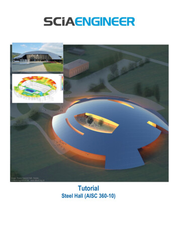
1800 STUDCOSteel Stud Systems - StudsSteel Stud SystemsThe Studco lipped wall studs are manufacturedin various widths and gauges from 0.50BMT to1.15BMT. Bell mouth service holes are punchedat 500mm centres eliminating the need forcabling grommets. The knurled face along thestud flange provides a positive screw pointlocation. Studs can be boxed or spliced toextend the overall length or to providestrengthening if required. Refer to Table 47 forsplice fixing details.Table 56SPLICE STUD FIXING DETAILWallHeight0-6000mmSplicePositionIn WallNo. of Fasteners for both sides of studs atsplice joint0.50 / 0.55 / 0.75BMT1.15BMT0 -10%2310% - 25%35Spliced Studs0.75 BMT - 150mm studs1.15 BMT - 64, 76, 92, 150mm studsSpliced Studs0.50 BMT - 51, 64mm studs0.55 BMT - 76, 92mm studs0.75 BMT - 51, 64, 76, 92mm studsMinimumoverlap500mmNote: 1.Splicing of studs is not suitable for load bearing wallsunless certified by an engineer.2.Splices to be alternated top and bottom along wall length3.Do not splice studs between 25% - 75% of wall height4.Maximum stud spacing 600mm centres.Boxed StudsBack to Back Studs0.50 & 0.55 BMT - all stud sizes0.75 & 1.15BMT - all stud sizesMinimumoverlap300mm500mmMaximumRefer to Table 47for fastenerrequirementsFig. 136Spliced Studs – Back to BackScrew through at maximum500mm centres.Volume 3.1Fig. 2Fig. 3Fig. 4Spliced Studs - BoxedBoxed Studs - Screw Fixingonly required if studs areunlined.Back to Back – Fixing for 1.15stud range in lieu of Boxing stud.Refer to Table 47 for fixing requirementssales@studcosystems.com.auRefer to Table 56 for fixing requirementsPH: 1800 788 326
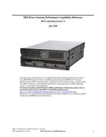
1800 STUDCOSteel Stud Systems - TracksDEFLECTION HEAD TRACK NOTES1) 0.55 D/TrackFor use in walls using 0.50 - 0.55 Stud up to 2.7m high, with a maximum internal pressure of 0.25kPa.2) 0.75 D/TrackTo be used in walls over 2.7m high or if the wall calls for 0.75 stud and/or the internal pressure is greater then 0.25 kPa.3) 1.15 D/TrackUse 1.15 D/Track for top & bottom tracks when a 1.15 stud wall exceeds 3.0m high and where the wall design calls for 1.15 stud system.4) Deflection Head Tracks should be used for top & bottom tracks when wall heights exceeds 4.8m.Fig. 1Fig. 2Bottom Track FixingNote:DPC is not required under thetrack unless specified otherwiseWall studSteel Stud SystemsThe Studco Track sections provide a friction fit for the lipped wall studs. The friction fit holds the studs in position until the lining boards are fixed; this friction fit also accommodates a slip joint to allow for any movementin the primary structure. To allow for this movement to occur it is not recommended that the lining board isfixed to the track sections unless specifically stated. Studco Track Sections are manufactured in two differentprofiles: a standard track with a nominal leg height of 32mm and the deflection head track with a nominal legheight of 50mm. The standard track is also available with a rolled hemmed edge. This safety hem along theentire length of the track section reduces the exposure to sharp edges whilst also enhancing the rigidity ofthe profile.Fixing CentresStuds should be orientated inthe same direction to makefitting of lining boards easierTrack fixings at600mm centresTrack sectionAcoustic sealant if required600mmFixing centres600mm100mm - Minimum end of track fixingNote:Use 2 fixings at 600mm centres for the 150mm track section,approximately 20mm in from either side of the track.Fig. 3Note:Where tracks are fastened to concrete minimum edgedistances for all fixings must be maintained.Fig. 4Friction FitDeflection HeadFixings at 600mm centresFixings at 600mm centres100mm max to first fixing5-10mmclearanceto stud20mmclearanceto stud100mm max to first fixingFasteners to liningboard as permanufacturer’sspecifications32mm track sectionFasteners to lining board as permanufacturers specificationsNote:Do not fix cornice to walls rigidlywhere friction joints are installed.Row of noggings100mm down requiredif wall lined one side.Note:Do not rigidly fix cornice to wallswhere deflection head is used.Volume 3.1PH: 1800 788 326sales@studcosystems.com.au37
1800 STUDCOSteel Stud Systems - NoggingsSteel Stud SystemsStudco noggings and nogging tracks are manufactured in a range of sizes to suit standard wall stud centres. Noggingtrack to suit custom centres and back to back studs is available. The use of noggings is to provide support and also toprevent twisting of the studs during the installation of the lining boards. Noggings also provide extra support to thewall construction, and in some instances a more cost effective design can be achieved by using noggings. Studcomanufactures two types of noggings, individual noggings or nogging track. Noggings are supplied as pre-cut individualnogging pieces to save cutting on site and can also be installed after the studs and tracks have been fitted. Noggingtrack is a continuous track that can be installed in stud framing in one length and requires only two screw fixings perstud connection. Timber noggings may be used, providing they are fixed as per diagram Fig. 3. Treated timber mustnot be used. The minimum number of noggings for different wall configurations can be established from Table 49. Thisis applicable for internal walls subjected to 0.25kPa. Walls connected to the underside of a concrete slab must beinstalled with deflection head track and an additional row of noggings 100mm down, if lined one side only.Fig. 3 Timber NoggingFig. 1 Nogging18mmFig. 2 Nogging TrackFix thru web of studsyTreated timbersmust not be usedx18mmxTable 57NOGGING 45N7675-60N9275-45N9275-60N1507-45N1507-60Nogging TrackCentres 0mm450mm600mmN/AN/AN/AN/AN/AN/AN/AN/ANoggingLength 12mm562mm412mm562mm412mm562mmxTable 58NOGGING REQUIREMENTSWall HeightWall LiningRows Of NoggingsRequired0 - 4.2m4.2m - 8.4m0 - 3.0m3.0m - 6.0m6.0m - 8.0mWall Lined Both Sides01123Wall Lined One SideNote: Walls connected to the underside of a concrete slab must beinstalled with deflection head track and additional row of noggins100mm down if unlined or lined one side only. If slotted deflection headtrack is used, additional row of noggins 100mm down not required.Volume 3.1sales@studcosystems.com.auPH: 1800 788 326
1800 STUDCOInstallation Guide - Wall to Ceiling IntersectionsFig. 1 Top Track to Bridging Support DetailFig. 2 Concealed Ceiling with Wall Parallel toSteel Stud SystemsFurring Channel DetailTrack fixed at maximum600mm centresBridging requirements to be specifiedM25/M27 Top Cross RailBridging fixed toprimary structure100mm Max to first fixingWhere walls runparallel to furringchannel provideextra furringchannel for fixing.Fig. 3 Concealed Ceiling with WallFig. 4 Exposed T-Bar Ceiling Connection DetailRight Angles Connection DetailM534 Spring HangerFix track into each intersecting main bar38M Main barM27/M25Top Cross RailFix track into eachfurring channelM29/M308Furring ChannelNote:Where studs are adjacentto doors and windowsand stud loads exceed0.25 kPa this constructionis not recommended.Fig. 5 Decorative Stopping Section with Wall Track DetailFix track into eachfurring channelExposed grid to be fixedwith brackets back toperimeter walls to stopceiling from movingFig. 6 Decorative Stopping Header Track DetailM29/M308Furring ChannelFix track into eachfurring channel100mm Max to first fixingSL10 Shadowlinestopping bead100mm Max to first fixingExtrudedaluminium tracksections for 64, 76& 92mm studs.Additional fixings maybe required nearintersecting walls.Volume 3.1PH: 1800 788 326sales@studcosystems.com.au39
1800 STUDCOInstallation Guide - Internal Stud WallsFig. 1 Door OpeningFig. 2 Window OpeningSteel Stud SystemsJamb studs to be fixed to toptrack or see page 43 fordeflection bracket connectionDoor/Window headerfrom track section fixedto jamb studs1000mm max*Jamb studs to beboxed at openings1500mm max*Stud centresshould match thestandard wallstud spacing* Door openings over 1000mm and external openings must bechecked prior to commencement of work.Fig. 3 Wall End Intersection to Concrete* Jamb studs to be boxed at openings,window openings over 1500mm andexternal openings must be checked prior tocommencement of work.100mmINTERNAL WALLS ONLYDESIGN NOT SUITABLEFOR EXTERIOR WALLSVertically fix with masonryfixings max 500mm centresFig. 4 Angle Bracket Connection* Resilient mount can also be used - see page 30.Masonry fixingMinimum 2 tek screws per connection* Bracket locations should be checked priorto commencement of work40Volume 3.1Volume 3.1sales@studcosystems.com.auPH: 1800 788 326
1800 STUDCOFig. 5 Wall EndFig. 6 CornerTrack fixingsEzy Cap wall end cap600mm100mm600mm max.fixing centres100mm max.first fixing point100mmWalls connected to theunderside of a concreteslab must be in
The Studco steel stud framing system is engineered to provide designers and installers the solution to create framing systems that are not only durable and versatile but can also achieve the needs and design criteria in accordance with the BCA and appropriate Australian standards. The Studco steel stud framing system is manufactured in a range of various widths, lengths and material gauges .