Transcription
After the foundation is built and the batter boards are removed, the carpenter builds theframework. The framework consists of beams, trusses, walls and partitions, flooring, ceilings,sheathing and siding, stairways, roof framing and coverings (Chapter 7), and doors andwindows (Chapter 8). This chapter familiarizes the carpenter with materials, tools, andtechniques used to build the framework.TYPES OF FRAMINGFraming consists of light, heavy, and expedient framing.LIGHT FRAMINGThere are three principal types of framing for light structures: western, balloon, and braced.Figure 6-1, page 6-2, illustrates these types of framing and specifies the nomenclature andlocation of the various members.Light framing is used in barracks, bathhouses, and administration buildings. Figure 6-2, page6-3, shows some details of a 20-foot wide building (such as ground level, window openings,braces, and splices) and labels the framing parts.Much of light framing can be done in staging areas while staking out, squaring, and floorframing is being done. Subflooring can begin when a portion of the floor joists has been laid.The better-skilled men should construct the frame, and with good coordination, a large force ofmen can be kept busy during framing.Western FrameThe western or platform frame (Figure 6-1, 1) is used extensively in military construction. It issimilar to the braced frame, but has boxed-sill construction at each floor line. Also note thatcross bridging is used between the joists and bridging is used between the studs. The platformframe is preferred for one-story structures since it permits both the bearing and nonbearingwalls (which are supported by the joist) to settle uniformly.Balloon FrameThe balloon frame (Figure 6-1, 2) is a widely used type of light framing. The major differencebetween balloon and braced framing in a multistory building is that in balloon framing thestuds run the full length, from sill to rafters. It is customary for second-floor joists to rest on a1- x 4-inch ribbon that has been set into the studs. The balloon frame is less rigid than a bracedframe.
Braced FrameA braced frame (Figure 6-1, 3) is much more rigid than a balloon frame. Exterior studs extendonly between floors and are topped by girts that form a sill for the joists of the succeeding floor.Girts are usually 4 x 6 inches. With the exception of studs, braced frame members are heavierthan those in balloon framing. Sills and corner posts are customarily 4 x 6 inches. Unlike thestuds, corner posts extend from sill to plate. Knee braces, usually 2 x 4 inches, are placeddiagonally against each side of the corner posts. Interior studding for braced frames is thesame as for balloon-frame construction.HEAVY FRAMINGHeavy-frame buildings are more permanent, and are normally used for warehouses and shops.Heavy framing is seldom used in TO construction. Figure 6-3, page 6-4, shows the details ofheavy framing. Heavy framing consists of framing members at least 6 inches in dimension(timber construction). Long, unsupported areas between walls are spanned by built-up rooftrusses.
EXPEDIENT FRAMINGSome field conditions require expedient framing techniques. For example— Light siding. Chicken wire and water-resistant bituminous paper can be sandwiched toprovide adequate temporary framing in temperate climates.Salvaged framing. Salvaged sheet metal, such as corrugated material or gasoline cans, canbe used as siding in the construction of emergency housing.Local timber. Poles trimmed from saplings or bamboo can be constructed into reasonablysound framing and may be secured with native vines if necessary.Wood-substitute framing. Adobe (soil, straw, and water—mixed until spreadable) can beused to form walls, floors, and foundations. A similar mixture may be used to form sundried bricks.Excavations. Proper excavation and simple log cribbing may also be covered with sod andcarefully drained to give adequate shelter.CONNECTIONS
Weak points in a structure usually occur at the connections (joints and splices) between piecesof lumber. However, these connections can be structurally sound if done correctly. Such weakpoints are usually a sign of poor workmanship.JOINTSJoints are connections between two pieces of timber that come together at an angle. The typesof joints most commonly used in carpentry are butt joints and lap joints.Butt JointsA butt joint is formed by placing the end of one board against another board so that the boardsare at an angle (usually a right angle), forming a corner. The types of butt joints are shown inFigure 6-4 and are described below.Straight Butt Joint. This joint is formed by placing the square-cut end of one board againstthe square face of another. The butt end of one board should be square and the face of the otherboard smooth so that they fit perpendicular to each other. Select the right type of nails orscrews to hold such a joint securely. For framing, butt joints are secured by 8d or 10d nails thatare toenailed to strengthen the joint. The end grain is the weakest part of a piece of wood whenused in joints. A butt joint is made at either one or two endgrain parts. It will be no stronger than the quality of thoseparts. A butt joint is, therefore, the weakest type of joint.This is especially true if the joint is made of two pieces ofwood only.Oblique Butt Joint. This joint is formed by butting themitered end of one board against the face of another board.Bracing is typically made with this joint. It should not beused where great strength is required. The strength of theoblique butt joint depends upon the nailing. The nail size
depends upon the timber size. Nails should be toenailed to strengthen the joint; not too manynails should be used.Miter Butt Joint. This joint is formed by bringing themitered ends of two boards together to form the desiredangle. This joint is normally used at corners where astraight butt joint would not be satisfactory. To form aright-angle miter joint (the most commonly used), cut eachpiece at a 45 angle so that when the pieces are joined theywill form a 90 angle. The miter joint is used mostly inframing. However, it is a very weak joint and should not beused where strength is important.Lap JointsThe lap joint is the strongest joint. Lap joints (Figure 6-5)are formed in one of two ways: a plain lap joint or a half-lapsplice joint.Plain Lap Joint. This joint is formed by laying one boardover another and fastening the two with screws or nails.This is the simplest and most often used method of joining.This joint is as strong as the fasteners and material used.Half-Lap Splice Joint. This joint is formed by cuttingaway equal-length portions (usually half) from the thicknessof two boards. The two are then joined so that they overlapand form a corner. Overlapping surfaces must fit snugly andsmoothly. Overlaps should be sawed on the waste side of thegauge line, to avoid cutting laps oversize by the thickness ofthe cut. This joint is relatively strong and easy to make.NOTE: Some useful variations of the half-lap joint arethe cross-lap, the middle-lap, and the mitered half-lapjoints.SPLICESSplices connect two or more pieces of material that extend inthe same line. The joint will be as strong as the unjoinedportions. The type of splice used depends on the type ofstress and strain that the spliced timber must withstand. Vertical supports (longitudinal stress) require splicesthat resist compression.Trusses, braces, and joists (transverse and angularstress) require splices that resist tension.Horizontal supports, such as girders or beams, requiresplices that resist bending tension and compression.
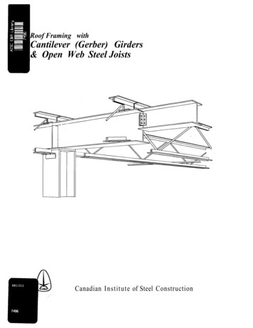
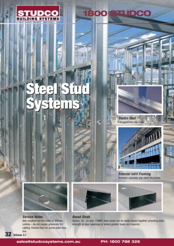
For example, splices for resistingcompression are usually worthlessfor resisting tension or bending.Figure 6-6 shows splice types;Figure 6-7 shows splice stresses.Compression-ResistantSplices. Compression-resistantsplices support weight or exertpressure and will resistcompression stress only. The mostcommon types of compressionresistant splices are the butt spliceand the halved splice.Figure 6-7. Splice stressesButt Splice. This splice is constructed by butting the squared ends of two pieces of timbertogether and securing them in this position with two wood or metal pieces fastened on oppositesides of the timber. The two short supporting pieces keep the splice straight and preventbuckling. Metal plates used as supports in a butt splice are called fishplates. Wood plates arecalled scabs and are fastened in place with bolts or screws. Bolts, nails, or corrugated fastenersmay be used to secure scabs. If nails are used with scabs, they are staggered and driven at anangle away from the splice. Too many nails, or nails that are too large, will weaken a splice.Halved Splice. This splice is made by cutting away half the thickness of equal lengths fromthe ends of two pieces of timber, then fitting the tongues (laps) together. The laps should belong enough to provide adequate bearing surfaces. Nails or bolts may be used to fasten thehalved splice. Note: To give the halved splice resistance to tension as well ascompression, fishplates or scabs may be used.Tension-Resistant SplicesIn members such as trusses, braces, and joists, the joint undergoes stress in more than onedirection; this creates tension, buckling the member in a predictable direction. Tensionresistant splices provide the greatest practical number of bearing surfaces and shoulderswithin the splice.Square Splice. This splice is a modification of the compression halved splice. Notches are cutin the tongues or laps to provide an additional locking shoulder. The square splice may befastened with nails or bolts. Note: It may be greatly strengthened by using fishplates orscabs.Long, Plain Splice. This splice is a hasty substitute for the square splice. A long overlap oftwo pieces is desirable to provide adequate bearing surface and enough room for fasteners tomake up for the lack of shoulder lock.Bend-Resistant SplicesHorizontal timbers supporting weight undergo stress at a splice that results in compression ofthe upper part; this has a tendency to crush the fibers. Tension of the lower part also tends to
pull the fibers apart. Bend-resistant splices resist both compression and tension. Make a bendresistant splice as follows:Step 1. Cut oblique, complementary laps in the end of two pieces of timber.Step 2. Square the upper lap (bearing surface) to butt it against the square of the other lap.This offers maximum resistance to crushing.Step 3. Bevel the lower tongue.Step 4. Fasten a scab or fishplate along the bottom of the splice to prevent separation of thepieces.NOTE: When this splice cannot be done, a butt joint, halved splice, or square splicesecured by fishplates or scabs may be used.SILLSThere are four types of wood sill construction: platform construction, balloon-framedconstruction, braced-framed construction, and the builtup sill. The sill is the foundation thatsupports a building and is the first part of a building to be set in place. It rests directly on thefoundation posts or on the ground and is joined at the corners and spliced when necessary.Figure 6-8, page 6-8, shows the most common sills. The type of sill used depends on the type ofconstruction used in the frame. To prevent air from entering into the building, spread a thinbed of mortar on top of the foundation wall. This also provides a solid base for the sill. Anothertechnique is to use a sill sealer made of fiberglass. Place insulation material and a termiteshield under the sill if desired.PLATFORM CONSTRUCTIONBox sills are commonly used with platform framing, which is the most common type of framing.These may be used with or without the sill plate.The sill or sill plate is anchored to the foundation wall for supporting and fastening joists witha header at the end of the joists resting on the foundation wall. In this type of sill, the sill islaid edgewise on the outside edge of the sill plate.BALLOON-FRAMED CONSTRUCTION“T” sills are usually used in balloon framing. There are two types of T-sills: one for dry, warmclimates and one for colder climates. They are made the same, except that in the latter case thejoists are nailed directly to the studs and sills and headers are used between the floor joists.BRACED-FRAMING SILLSBraced-framing sills (Figure 6-8) are usually used in braced-framing construction. The floorjoists are notched and nailed directly to the sill and studs.
BUILT-UP SILLSIf posts are used in the foundation, use either sills made of heavy, single timbers or built-upsills. Built-up sills are made with two or more light timbers, such as 2 x 4s. A built-up sill isused when heavy, single timbers are not available and lighter lumber (such as a 2 x 4) alonewould not support the building load. Figure 6-9 shows how to make a corner joint for a builtupsill.Whether heavy timber or built-up sills are used, the joints should be over posts. The size of thesill depends on the load to be carried and the spacing of the posts. The sill plates are laiddirectly on the post or, in expedient framing, directly on graded earth. When earth floors areused, nail the studs directly to the sill.GIRDERSThe distance between two outsidewalls is usually too great to bespanned by a single joist. A girderis used for intermediate supportwhen two or more joists areneeded to cover the span. A girderis a large beam that supportsother smaller beams or joists. Agirder may be made of timber,steel, reinforced concrete, or acombination of these materials.Wooden girders are more commonthan steel in light-framebuildings. Built-up and solid
girders should be of seasoned wood. Common types of wood girders include solid, built-up,hollow, and glue-laminated. Hollow beams resemble a box made of 2 x 4s, with plywood webs.They are often called box beams. Built-up girders are usually made of several pieces of framinglumber (Figure 6-10). Built-up girders warp less easily than solid wooden girders and are lesslikely to decay in the center.Girders carry a large part of the building weight. They must be rigid and properly supported atthe foundation walls and on the columns. They must be installed properly to support joists. Theends of wood girders should bear at least 4 inches on posts.CAUTION Precautions must be taken to avoid or counteract any future settling orshrinking, which would cause distortion of the building.A girder with a ledger board is used where vertical space is limited. This provides moreheadroom in basements and crawl spaces. A girder with joist hangers is used where there islittle headroom or where the joists must carry an extremely heavy load. These girders areshown in Figure 6-11, page 6-10.SIZE REQUIREMENTSCarpenters should understand the effect of length, width, and depth on the strength of woodgirders before attempting to determine their size.Principles that govern the size of a girder are the Distance between girder posts. Girder load area. Total floor load on the girder per square foot. Load on the girder per linear foot. Total load on the girder. Material to be used. Wood moisture content and types of wood used, since some woods are stronger than others.
A girder should be just large enough to support an ordinary load. Any size larger than thatwastes material. For greater carrying capacity, it is better to increase a girder's depth (withinlimits) than its width. When the depth of a girder is doubled (the width of lumber, such as 2 x 8or 2 x 6), the safe load increases four times. For example, a girder 3 inches wide and 12 inchesdeep will carry four times as much weight as a girder 3 inches wide and 6 inches deep. Table 61 gives the sizes of built up wood girders for various loads and spans.LOAD AREAA building load is carried by foundation walls and the girder. Because the ends of each joistrest on the girder, there is more weight on the girder than on any of the walls. Beforeconsidering the load on the girder, it may be well to consider a single joist.Example 1. Suppose a 10-foot plank weighing 5 pounds per foot is lifted by two men. If the menwere at opposite ends of the plank, they would each support 25 pounds.Now assume that one of these men lifts the end of another 10-foot plank of the same weight asthe first one. A third man lifts the opposite end of that plank. The two men on the outside areeach now supporting one-half of the weight of one plank (25 pounds apiece), but the man in thecenter is supporting one-half of each of the two planks (50 pounds).The two men on the outside represent the foundation walls. The center man represents thegirder. The girder carries one-half of the weight, and the other half is equally divided betweenthe outside walls. However, the girder may not always be located halfway between the outerwalls.Example 2. Imagine the same three men lifting two planks that weigh 5 pounds per foot. Oneof the planks is 8 feet long and the other is 12 feet long. The total length of these two planks isthe same as before. The weight per foot is the same, so the total weight in both cases is 100pounds.
One of the outside men issupporting one-half of the 8foot plank) or 20 pounds. Theman on the opposite outsideend is supporting one-half ofthe 12-foot plank, or 30pounds. The man in the centeris supporting one-half of eachplank (50 pounds). This is thesame total weight he waslifting before.NOTE: To determine thegirder load area: a girderwill carry the weight of thefloor on each side to themidpoint of the joists thatrest upon it.FLOOR LOADAfter the girder load area isknown, the total floor load persquare foot must bedetermined, for safetypurposes. Both dead and liveloads must be considered.Dead LoadThe dead load consists of allbuilding structure weight. Thedead load per square foot offloor area is carried directly orindirectly to the girder bybearing partitions. The deadload varies according to theconstruction method andbuilding height. The structuralparts in the dead load are— Floor joists for all floorlevels.Flooring materials, including the attic if it is floored.Bearing partitions.Attic partitions.Attic joists for the top floor.Ceiling laths and plaster, including the basement ceiling if it is plastered.
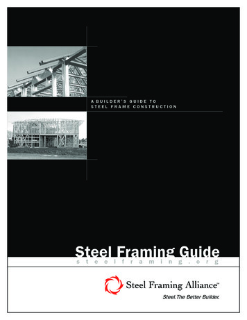
The total dead load for a light-frame building similar to an ordinary frame house is the deadload allowance per square foot of all structural parts added together. The allowance for an average subfloor, finish floor, and joists without basement plastershould be 10 pounds per square foot. If the basement ceiling is plastered, allow an additional 10 pounds per square foot. If the attic is unfloored, make a load allowance of 20 pounds for ceiling plaster and joistswhen girders or bearing partitions support the first-floor partition. If the attic is floored and used for storage, allow an additional 10 pounds per square foot.Live LoadThe live load is the weight of furniture, persons, and other movable loads, not actually a part ofthe building but still carried by the girder. The live load per square foot will vary according tothe building use and local weather conditions. Snow on the roof is also a part of the live load. Allowance for the live load on floors used for living purposes is 30 pounds per square foot. If the attic is floored and used for light storage, allow an additional 20 pounds per squarefoot. The allowance per square foot for live loads is usually governed by local buildingspecifications and regulations.The load per linear foot on the girder is easily figured when the total load per square foot offloor area is known.Example. Assume that the girder load area of the building shown in Figure 6-12 is sliced into1-foot lengths across the girder. Each slice represents the weight supported by 1 foot of thegirder. If the slice is divided into 1-foot units, each unit will represent 1 square foot of the totalfloor area. To determine the load per linear foot of girder, multiply the number of units by thetotal load per square foot.Note in Figure 6-12 that the girder is off-center. Remember that half of the load is supportedby the girder and half by the foundation walls. Therefore, the joist length to be supported onone side of the girder is 7 feet (one half of 14 feet) and the other side is 5 feet (one half of 10feet), for a total distance of 12 feet across the load area. Since each slice is 1 foot wide, it has atotal floor area of 12 square feet.Assume that the total floor load for each square foot is 70 pounds. Multiply the length timesthe width to get the total square feet supported by the girder (7 feet x 12 feet 84 square feet).84 square feet x 70 pounds per square feet (live and dead load) 5,880 pounds total load on thegirderBUILT-UP GIRDERSFigure 6-10, page 6-9, shows a built-up girder. Notice that the joists rest on top of the girder.This type of girder is commonly used in frame building construction. To make a built-up girder,select lumber that is as free from knots and other defects as possible.
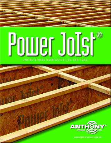
Built-up girders are usually madeof three pieces of framing lumbernailed together. (The pieces mustbe nailed securely to preventindividual buckling.) For properarrangement of the pieces oflumber, the end grains shouldmatch the example in Figure 613. The nailing pattern should besquare across the ends of theboard (1 1/2 inches from each end)and then diagonal every 16 inchesas shown in Figure 6-13. Thispattern increases the strength ofthe girder. A typical two- or threepiece girder of 2-inch lumber should be nailed on both sides with 16d common nails.SPLICINGMethods for splicing girders differ according to whether the girder is built-up or solid-beam.Built-Up GirdersThe lumber for a built-up girdershould be long enough so that nomore than one joint will occurover the span between footings.The joints in the beam should bestaggered, and the planks mustbe squared at each joint andbutted tightly together.Solid-Beam GirdersTo splice solid beams, use halflap joints or butt joints (Figure 614.) See Splices on page 6-6.Half-Lap. Sometimes a half-lapjoint is used to join solid beams (Figure 6-14). This is done by performing the following steps:Step 1. Place the beam on one edge so that the annual rings run from top to bottom.Step 2. Lay out the lines for the half-lap joint as shown in Figure 6-14.Step 3. Make cuts along these lines, then check with a steel square to ensure a matching joint.Step 4. Repeat the process on the other beam.Step 5. Nail a temporary strap across the joint to hold it tightly together.
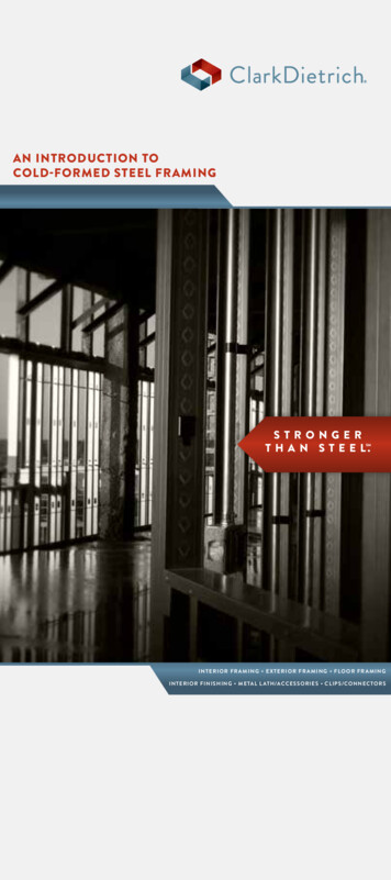
Step 6. Drill a hole through the joint with a drill bit about 1/16 inch larger than the bolt to beused, and fasten the joint with a bolt, a washer, and a nut.Butt Joints. When a strapped butt joint is used to join solid beams (Figure 6-14, page 6-13),the ends of the beams should be cut square. The straps, which are generally 18 inches long, arebolted to each side of the beams.GIRDER SUPPORTSWhen building a small frame building, the carpenter should know how to determine the propersize of girder supports (calledcolumns or posts).A column or post is a verticalmember that supports the liveand dead loads placed upon it.It may be made of wood,metal, or masonry. Wooden columns may besolid timbers or severalpieces of framing lumbernailed together with 16d or20d common nails.Metal columns are made ofheavy pipe, large steelangles, or I-beams.A column must have a bearingplate at the top and bottomwhich distributes the load evenly
across the column. Basement posts that support girders should be set on masonry footings. Columnsshould be securely fastened at the top to the load-bearing member and at the bottom to the footing onwhich they rest.Figure 6-15 shows a solid wooden column with a metal bearing cap drilled to permit fasteningit to the girder. The bottom of this type of column may be fastened to the masonry footing by ametal dowel. The dowel should be inserted in a hole drilled in the bottom of the column and inthe masonry footing. The base is coated with asphalt at the drilling point to prevent rust or rot.A good arrangement of a girder and supporting columns for a 24- x 40-foot building is shown inFigure 6-16. Column B will support one-half of the girder load between wall A and column C. Column C will support one-half of the girder load between columns B and D. Column D will share equally the girder loads with column C and wall E.GIRDER FORMSForms for making concrete girders and beams are made from 2-inch-thick material dressed onall sides. The bottom piece of material should be constructed in one piece to avoid using cleats.The temporary cleats shown in Figure 6-17 are nailed on to prevent the form from collapsingwhen handled.FLOORINGAfter the foundation and deck framing of a building are completed, the floor is built.FLOOR JOISTSJoists are the wooden members, usually 2 or 3 inches thick, that make up the body of the floorframe (Figure 6-18, page 6-16). The flooring or subflooring is nailed to the joists. Joists as small
as 2 x 6 are sometimes used in light frame buildings. These are too small for floors with spansover 10 feet, but are frequently used for ceiling joists.Joists usually carry a uniform loadof materials and personnel; theseare live loads. The weight of joistsand floors is a dead load. The joistscarry the flooring load directly onends nearest the sills, girders,bearing partitions, or bearingwalls. Joists are spaced 16 or 24inches apart, center to center.Sometimes the spacing is 12inches, but where such spacing ismade necessary by the load,heavier joists should be used.To support heavily concentratedloads or a partition wall, you mayneed to double the joist or placetwo joists together. Two typicalreinforced joists are shown inFigure 6-19.In joining joists to sills, be surethat the connection can hold theload that the joist will carry. The joist-connecting method in Figure 6-20, A, is used most oftenbecause it provides the strongest joint. The methods shown in Figure 6-20, B and C, are usedwhen it is not desirable to use joists on top of the sill. The ledger plate should be securelyfastened. If the joist must be notched, it should not be notched to the sill and girder over onethird of its depth to prevent splitting (Figure 6-20, D).Joists must be level when framed to girders. If the girder is not the same height as the sill, thejoist must be notched as shown in Figure 6-20, C. If the girder and sill are the same height, thejoists must be framed to keep the joist level. The joist is always placed crown up. Thiscounteracts the weight on the joists. In most cases there will be no sag below a straight line.
The simplest way to carry joists on steel girders is torest them on top (as shown in Figure 6-20, E), providedheadroom is not restricted. If there is a lack ofheadroom, use straps or hangers (iron stirrups) asshown in Figure 6-20, F. These art among the strongestjoist supports.In connecting joists to girders and sills where posts areused, a 2 x 4 is nailed to the face of the sill or girder,flush with the bottom edge. This is called a ledger.These pieces should be nailed securely with 20d nailsspaced 12 inches apart. When 2 x 6 or 2 x 8 joists areused, it is better to use 2 x 4 ledgers. This preventsjoists from splitting at the notch.When joists are 10 inches or more deep, 2 x 4s may beused as ledgers without reducing the strength of thejoists. If a notch is used, joist ties may be used toovercome this loss of strength. These ties are short 1 x 4boards nailed across the joists. Board ends are flushwith the top and bottom edges of the joists.Overhead joists are joined to plates as shown in Figure6-21, A and B. The inner end of the joist rests on the partition wall plates. If a joist is to rest onplates or girders, the joist is cut long enough to extend the full width of the plate or girder.Alternatively, the joists are cut to meet in the center of the plate or girder and connected with
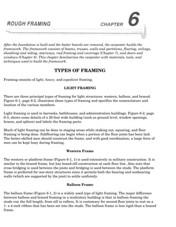
a scab. When the ends of twojoists lie side by side on theplate, they should be nailedtogether. Joists may also bejoined to girders with ledgers(Figure 6-21, C and D).FLOOR JOISTS FORPLATFORM CONSTRUCTIONCheck the plans to determine thesize and direction of the joists. Ifthe sizes for joists are notspecified on the plans, consultTables 6-2 and 6-3 to determinethe appropriate size.FLOOR BRIDGINGJoists tend to twist from side toside, especially when used over along span. Floor frames arebridged for stiffening and to prevent unequal deflection of the joists. This stiffening alsoenables an overloaded joist to receive some help from the joists on either side of it. A patternfor the bridging stock is obtained by placing a piece of material between the joists, thenmarking and sawing it. When sawed, the cut will form the correct angle.
The three kinds of bridging are:solid (horizontal) bridging,cross bridging, and compressionbridging (Figure 6-22, page 620). Cross bridging is used mostoften. It is very effective andrequires less time thanhorizontal bridging. Crossbridging looks like a cross andis made of pieces of lumber,usually diagonally cut 1 x 3 or 2x 3 between the floor joists.Each piece is nailed to the topof each joist and forms a cross(x) between the joists. Crossbridging should be made so thatthe two pieces of the cross areagainst each other.Compression is metal bridgingbetween joists.Bridging should be nailed atthe tops with 8d or 11 Id nails,and the bottoms should be leftfree until the subfloor is laid. This allows the joists to adjust to their final position and keepsthe bridging from pushing up the joists and causing unevenness in the floor. The bottom endsof the bridging may then be nailed, forming a continuous truss across the floor. This preventsoverloaded joists from sagging.Cutting and fitting the bridging by hand is a slow process. A power saw should be used if it isavailable. One line of bridging should be placed on joists more than 8 feet long. On joists morethan 16 feet long, two lines should be used.Table 6
techniques used to build the framework. TYPES OF FRAMING Framing consists of light, heavy, and expedient framing. LIGHT FRAMING There are three principal types of framing for light structures: western, balloon, and braced. Figure 6-1, page 6-2, illustrates these types of framing and specif