Transcription
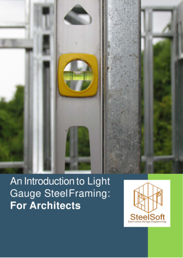
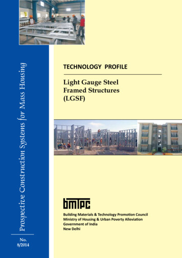
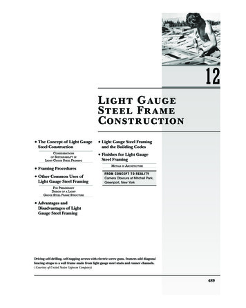
12Light GaugeSteel FrameConstruction The Concept of Light GaugeSteel ConstructionCONSIDERATIONSSUSTAINABILITY INLIGHT GAUGE STEEL FRAMINGOF Framing Procedures Other Common Uses ofLight Gauge Steel Framing Light Gauge Steel Framingand the Building Codes Finishes for Light GaugeSteel FramingMETALS IN ARCHITECTUREFROM CONCEPT TO REALITYCamera Obscura at Mitchell Park,Greenport, New YorkFOR PRELIMINARYDESIGN OF A LIGHTGAUGE STEEL FRAME STRUCTURE Advantages andDisadvantages of LightGauge Steel FramingDriving self-drilling, self-tapping screws with electric screw guns, framers add diagonalbracing straps to a wall frame made from light gauge steel studs and runner channels.(Courtesy of United States Gypsum Company)489JWBK274 Ch12.indd 48910/30/08 4:30:34 AM
To manufacture the members used in light gauge steel frameconstruction, sheet steel is fed from continuous coils throughmachines at room temperature that cold-work the metal (seeChapter 11) and fold it into efficient structural shapes, producinglinear members that are stiff and strong. Thus, these membersare referred to as cold-formed metal framing to differentiate themfrom the much heavier hot-rolled shapes that are used in structural steel framing. The term “light gauge” refers to the relativethinness (gauge) of the steel sheet from which the members aremade.The Concept ofLight Gauge SteelConstructionLight gauge steel construction is thenoncombustible equivalent of woodlight frame construction. The external dimensions of the standard sizesof light gauge members correspondclosely to the dimensions of the standard sizes of nominal 2-inch (38-mm)framing lumber. These steel membersare used in framing as closely spacedstuds, joists, and rafters in much thesame way as wood light frame members are used, and a light gauge steelframe building may be sheathed, insulated, wired, and Þnished insideand out in the same manner as awood light frame building.The steel used in light gaugemembers is manufactured to ASTMstandard A1003 and is metalliccoated with zinc or aluminum-zincalloy to provide long-term protectionagainst corrosion. The thickness ofthe metallic coating can be varied,depending on the severity of the environment in which the members willbe placed. For studs, joists, and rafters, the steel is formed into C-shapedcee sections (Figure 12.1). The webs ofcee members are punched at the factory to provide holes at 2-foot (600mm) intervals; these are designed toallow wiring, piping, and bracing topass through studs and joists withoutthe necessity of drilling holes on theconstruction site. For top and bottom wall plates and for joist headers,channel sections are used. The strengthand stiffness of a member dependon the shape and depth of the section and the gauge (thickness) of thesteel sheet from which it is made. Astandard range of depths and gaugesis available from each manufacturer.Commonly used metal thicknessesfor loadbearing members range from0.097 to 0.033 inch (2.46Ð0.84 mm)and are as thin as 0.018 inch (0.45mm) for nonloadbearing members(Figure 12.2).At least one manufacturer produces nonloadbearing light gaugesteel members by passing steel sheetthrough rollers with mated patternedsurfaces, producing a dense array ofdimples in the metal of the formedmembers. The additional cold working of the metal that occurs duringthe forming process and the ÞnishedFigure 12.1Typical light gauge steel framing members. To the left are the common sizes of ceestuds and joists. In the center are channel studs. To the right are runner channels.490JWBK274 Ch12.indd 49010/30/08 4:30:36 AM
The Concept of Light Gauge Steel Construction/ 491CONSIDER ATIONS OF SUSTAINABILITYIN LIGHT GAUGE STEEL FRAMINGIn addition to the sustainability issues raised in the previous chapter, which also apply here, the largest issue concerning the sustainability of light gauge steel constructionis the high thermal conductivity of the framing members.If a dwelling framed with light gauge steel members isframed, insulated, and Þnished as if it were framed withwood, it will lose heat in winter at about double the rateof the equivalent wood structure. To overcome this limitation, energy codes now require light gauge steel framedbuildings constructed in cold regions, including most ofthe continental United States, to be sheathed with plasticfoam insulation panels in order to eliminate the extensivethermal bridging that can otherwise occur through thesteel framing members.patterned surface result in membersmade from thinner sheet stock that areequal in and strength and stiffness toconventionally formed members produced from heavier gauge material.For large projects, members maybe manufactured precisely to the required lengths. Otherwise, they arefurnished in standard lengths. Members may be cut to length on theconstruction job site with power sawsor special shears. A variety of sheetmetal angles, straps, plates, channels,and miscellaneous shapes are manufactured as accessories for light gaugesteel construction (Figure 12.3).Light gauge steel members areusually joined with self-drilling, selftapping screws, which drill their ownholes and form helical threads in theholes as they are driven. Driven rapidly by hand-held electric or pneumatic tools, these screws are platedwith cadmium or zinc to resist corrosion, and they are available in anassortment of diameters and lengthsFigure 12.2Minimum thicknesses of base sheetmetal (not including the metallic coating)for light gauge steel framing members.Traditional gauge designations are alsoincluded (note how lower gauge numberscorrespond to greater metal thickness).Gauge numbers are no longer recommended for specification of sheet metalthickness due to lack of a uniform standard for the translation between thesenumbers and actual metal thickness.Sheet metal thickness may also be specified in mils, or thousandths of an inch.For example, a thickness of 0.033 inchcan be expressed as 33 mils.JWBK274 Ch12.indd 491Even with insulating sheathing, careful attentionmust be given to avoid undesired thermal bridges. Forexample, on a building with a sloped roof, a signiÞcantthermal bridge may remain through the ceiling joist-rafterconnections, as seen in Figure 12.4b. Foam sheathing onthe inside wall and ceiling surfaces is one possible way toavoid this condition, but adding insulation to the insideof the metal framing exposes the studs and stud cavitiesto greater temperature extremes and increases the risk ofcondensation. It also still allows thermal bridging throughthe screws used to fasten interior gypsum wallboard to theframing. Though small in area, these thermal bridges canreadily conduct heat and result in spots of condensationon interior Þnish surfaces in very cold weather.to suit a full range of connection situations. Welding is often employed toassemble panels of light gauge steelframing that are prefabricated in afactory, and it is sometimes used onthe building site where particularlystrong connections are needed. Other fastening techniques that are widely used include hand-held clinchingdevices that join members withoutscrews or welds and pneumaticallydriven pins that penetrate the members and hold by friction.Minimum Thickness of Steel SheetGauge12141618202225Loadbearing LightGauge Steel Framing0.097 (2.46 mm)0.068 (1.73 mm)0.054 (1.37 mm)0.043 (1.09 mm)0.033 (0.84 mm)Nonloadbearing LightGauge Steel Framing0.054 (1.37 mm)0.043 (1.09 mm)0.030 (0.75 mm)0.027 (0.69 mm)0.018 (0.45 mm)10/30/08 4:30:39 AM
492 /Chapter 12 Light Gauge Steel Frame ConstructionFigure 12.3END CLIPSWEB STIFFENERStandard accessories for light gaugesteel framing. End clips are used to joinmembers that meet at right angles. Foundation clips attach the ground-floor platform to anchor bolts embedded in thefoundation. Joist hangers connect joiststo headers and trimmers around openings. The web stiffener is a two-pieceassembly that is inserted inside a joistand screwed to its vertical web to helptransmit wall loads vertically through thejoist. The remaining accessories are usedfor bracing.FOUNDATION CLIPV-BRACINGFLAT STRAP BRACINGJOIST HANGER1 1/2" COLD ROLLED CHANNELFraming ProceduresThe sequence of construction fora building that is framed entirelywith light gauge steel members isessentially the same as that describedin Chapter 5 for a building framedwith nominal 2-inch (38-mm) woodmembers (Figure 12.4). Framing isusually constructed platform fashion: The ground ßoor is framed withsteel joists. Mastic adhesive is appliedto the upper edges of the joists, andwood panel subßooring is laid downand fastened to the upper ßanges ofthe joists with screws. Steel studs arelaid ßat on the subßoor and joinedJWBK274 Ch12.indd 492to make wall frames. The wall framesare sheathed either with wood panelsor, for noncombustible construction,with gypsum sheathing panels, which aresimilar to gypsum wallboard but withglass mat faces and a water-resistantcore formulation. The wall frames aretilted up, screwed down to the ßoorframe, and braced. The upper-ßoorplatform is framed, then the upperßoor walls. Finally, the ceiling and roofare framed in much the same way as ina wood-framed house. Prefabricatedtrusses of light gauge steel membersthat are screwed or welded togetherare often used to frame ceilings androofs (Figures 12.15 and 12.16). It ispossible, in fact, to frame any building with light gauge steel membersthat can be framed with nominal2-inch (38-mm) wood members.To achieve a more Þre-resistiveconstruction type under the building code, ßoors of corrugated steeldecking with a concrete toppingare sometimes substituted for woodpanel subßooring.Openings in ßoors and walls areframed analogously to openings inwood light frame construction, withdoubled members around each opening and strong headers over doorsand windows (Figures 12.5Ð12.9).Joist hangers and right-angle clips of10/30/08 4:30:40 AM
Framing ProceduresSteel/ 493joist roof raftersEnd clipRidge beam—nested steel joistsAnchor clipSteel joist roof rafterSteel joist soffitframingB EAVEA RIDGEStudFigure 12.4RunnerTypical light gauge framing details. Each detail is keyedby letter to a circle on the whole-building diagram in thecenter of the next page to show its location in the frame.(a) A pair of nested joists makes a boxlike ridge board orridge beam. (b) Anchor clips are sandwiched between theceiling joists and rafters to hold the roof framing down tothe wall. (c) A web stiffener helps transmit vertical forcesfrom each stud through the end of the joist to the stud inthe floor below. Mastic adhesive cushions the joint betweenthe subfloor and the steel framing. (d) Foundation clipsanchor the entire frame to the foundation. (e) At interiorjoist bearings, joists are overlapped back to back and a webstiffener is inserted.(continued)Continuous bead ofadhesiveWeb stiffenerClosurechannelC-runnerC JOIST BEARING AT UPPER FLOORRunner—fastenthrough plywoodinto closurePlywood subfloorWeb stiffenerSteel joistsGrout and shim asrequiredWeb stiffenerFoundation clipD JOIST BEARING AT FOUNDATIONJWBK274 Ch12.indd 493Steel stud or beamE INTERIOR JOIST BEARING10/30/08 4:30:40 AM
494 /Chapter 12 Light Gauge Steel Frame ConstructionCeiling joistsRafterSteel studAH GABLE END FRAMINGClosurechannel orjoist sectionBH1 1/2" x 20gauge bracingstrapCDEnd tabsEGFG JOIST PARALLEL TO END WALLClosure channel orjoist sectionFigure 12.4 (continued)( f, g) Short crosspieces brace the last joist at the end of thebuilding and help transmit stud forces through to the wallbelow. (h) Like all these details, the gable end framing isdirectly analogous to the corresponding detail for a woodlight frame building as shown in Chapter 5.F JOIST PARALLEL TO FOUNDATIONJWBK274 Ch12.indd 49410/30/08 4:30:40 AM
Framing ProceduresOpeningJoist hangerDouble joist header(nested)Steel joist framing intoheader/ 495Figure 12.5Headers and trimmers for floor openingsare doubled and nested to create a strong,stable box member. Only one verticalflange of the joist hanger is attachedto the joist; the other flange would beused instead if the web of the joist wereoriented to the left rather than the right.Double joist trimmer(nested)Figure 12.6Steel gusset plateRunner channelLintel—2 steel joistsA typical window or door head detail. The header is made oftwo joists placed with their open sides together. The top plateof the wall, which is a runner channel, continues over the topof the header. Another runner channel is cut and folded at eachend to frame the top of the opening. Short studs are insertedbetween this channel and the header to maintain the rhythm ofthe studs in the wall.Steel studJWBK274 Ch12.indd 49510/30/08 4:30:40 AM
496 /Chapter 12 Light Gauge Steel Frame ConstructionFigure 12.7Diagonal strap braces stabilize upperfloor wall framing for an apartmentbuilding. (Courtesy of United States GypsumCompany)Figure 12.8Temporary braces support the walls ateach level until the next floor platformhas been completed. Cold-rolledchannels pass through the web openingsof the studs; they are welded to each studto help stabilize them against buckling.(Courtesy of Unimast Incorporated—www.unimast.com)JWBK274 Ch12.indd 49610/30/08 4:30:40 AM
Framing Procedures/ 497Figure 12.9A detail of a window header. Because asupporting stud has been inserted underthe end of the header, a large gussetplate such as the one shown in Figure12.6 is not required. (Courtesy of UnimastIncorporated—www.unimast.com)Figure 12.10Ceiling joists in place for an apartmentbuilding. A brick veneer cladding hasalready been added to the ground floor.(Courtesy of United States Gypsum Company)JWBK274 Ch12.indd 49710/30/08 4:30:42 AM
498 /Chapter 12 Light Gauge Steel Frame Constructionsheet steel are used to join membersaround openings. Light gauge members are designed so that they can benested to form a tubular conÞgurationthat is especially strong and stiff whenused for a ridge board or header(Figures 12.4a and 12.5).Because light gauge steel members are much more prone than theirwood counterparts to twisting or buckling under load, somewhat more attention must be paid to their bracing andbridging. The studs in tall walls aregenerally braced at 4-foot (1200-mm)intervals, either with steel strapsscrewed to the edges of the studs orwith 1½-inch (38-mm) cold-formedsteel channels passed through thepunched openings in the studs andwelded or screwed to an angle clip ateach stud (Figure 12.8). Floor joistsare bridged with cee-joist blockingbetween and steel straps screwed totheir top and bottom edges. In locations where large vertical forces mustpass through ßoor joists (as occurswhere loadbearing studs sit on theedge of a ßoor platform), steel webstiffeners are screwed to the thin websof the joists to prevent them frombuckling (Figure 12.4c,e). Wall bracing consists of diagonal steel strapsscrewed to the studs (chapter-openingphoto, Figure 12.7). Permanent resistance to buckling, twisting, and lateralloads such as wind and earthquake isimparted largely and very effectivelyby subßooring, wall sheathing, andinterior Þnish materials.Figure 12.11A detail of eave framing. (Courtesy ofUnimast Incorporated—www.unimast.com)Figure 12.12A power saw with an abrasive bladecuts quickly and precisely through steelframing members. (Courtesy of UnimastIncorporated—www.unimast.com)JWBK274 Ch12.indd 49810/30/08 4:30:43 AM
Other Common Uses of Light Gauge Steel FramingOther Common Usesof Light Gauge SteelFramingLight gauge steel members are usedto construct many components ofÞre-resistant buildings whose structuresare made of structural steel, concrete,or masonry. These components includeinterior walls and partitions (Chapter23), suspended ceilings (Chapter 24),and fascias, parapets, and backup wallsfor such exterior claddings as masonryveneer, exterior insulation and Þnishsystem (EIFS), glass-Þber-reinforcedconcrete (GFRC), metal panels, andvarious thin stone cladding systems(Chapters 19 and 20; see also Figures12.13 and 12.14). Light gauge steelmembers used for framing interior partitions and other nonloadbearing applications are properly referred to andspeciÞed as nonstructural metal framing,as distinct from cold-formed metal framing, the latter term reserved for lightgauge steel members used in structuralapplications and exterior wall claddingsystems (even though both types ofmembers are, in fact, cold-formed).Light gauge steel studs can be combined with concrete to produce thin,but relatively stiff, wall panel systems.Both loadbearing and nonloadbearingpanels can be made that are suitable foruse in residential and light commercial/ 499buildings. A variety of productionmethods are possible that generally involve casting an approximately 2-inch(50-mm)-thick concrete facing onto aframework of steel studs. The concretemay be sitecast (on the building site) orprecast (in a factory). The concrete-tosteel bond may be created by a variety ofdevices welded or screwed to the studsthat then become embedded in theconcrete, such as stud anchors, sheetmetal shear strips, welded wire reinforcing, or expanded metal. In loadbearing applications, the concrete panelsprovide shear resistance while the steelstuds provide most of the resistance togravity loads and to wind loads actingperpendicular to the face of the panel.Figure 12.13Light gauge steel stud walls frame the exterior walls of a building whose floors androof are framed with structural steel. (Courtesy of Unimast Incorporated—www.unimast.com)JWBK274 Ch12.indd 49910/30/08 4:30:44 AM
500 /Chapter 12 Light Gauge Steel Frame ConstructionFigure 12.14The straightness of steel studs is apparentin these tall walls that enclose a buildingframed with structural steel.(Courtesy of Unimast Incorporated—www.unimast.com)JWBK274 Ch12.indd 50010/30/08 4:30:45 AM
Other Common Uses of Light Gauge Steel Framing/ 501Figure 12.15A worker tightens the last screws tocomplete a connection in a light gaugesteel roof truss. The truss members areheld in alignment during assembly by asimple jig made of plywood and blocksof framing lumber. (Courtesy of UnimastIncorporated—www.unimast.com)Figure 12.16Installing steel roof trusses. (Courtesy ofUnimast Incorporated—www.unimast.com)JWBK274 Ch12.indd 50110/30/08 4:30:46 AM
502 /Chapter 12 Light Gauge Steel Frame ConstructionFOR PRELIMINARY DESIGN OF A LIGHT GAUGE STEEL FRAME STRUCTURE Estimate the depth of rafters on the basis of the horizontal (not slope) distance from the outside wall of the building to the ridge board in a gable or hip roof and the horizontal distance between supports in a shed roof. Estimatethe depth of a rafter at 1Ⲑ24 of this span, rounded up to thenearest 2-inch (50-mm) dimension. The depth of light gauge steel roof trusses is usuallybased on the desired roof pitch. A typical depth is onequarter of the width of the building, which corresponds toa 6Ⲑ12 pitch. Estimate the depth of light gauge steel floor joists as 1Ⲑ20of the span, rounded up to the nearest 2-inch (50-mm) dimension. For loadbearing studs, add up the total width of ßoorand roof slabs that contribute load to the stud wall. A 35Ⲑ8-inch (92-mm) or 4-inch (102-mm) stud wall can supporta combined width of approximately 60 feet (18 m), and a6-inch (152-mm) or 8-inch (203-mm) stud wall can supporta combined width of approximately 150 feet (45 m).In situations where noncombustibility is not a requirement, metal andwood light framing are sometimesmixed in the same building. Somebuilders Þnd it economical to usewood to frame exterior walls, ßoors,and roof, with steel framing for interiorpartitions. Sometimes all walls, interior and exterior, are framed with steel,and ßoors are framed with wood. Steeltrusses made of light gauge membersmay be applied over wood frame walls.In such mixed uses, special care mustbe taken in the details to ensure thatwood shrinkage will not create unforeseen stresses or damage to Þnish materials. Steel framing also may be used inlieu of wood where the risk of damagefrom termites is very high.Advantages andDisadvantages ofLight Gauge SteelFramingLight gauge steel framing sharesmost of the advantages of wood lightJWBK274 Ch12.indd 502 For exterior cladding backup walls, estimate that a3 5Ⲑ8 -inch (92-mm) stud may be used to a maximum heightof 12 feet (3.7 m), a 6-inch (150-mm) stud to 19 feet(5.8 m), and an 8-inch (100-mm) stud to 30 feet (9.1 m).For brittle cladding materials such as brick masonry, selecta stud that is 2 inches (50 mm) deeper than these numberswould indicate.All framing members are usually spaced at 24 inches(600 mm) o.c.These approximations are valid only for purposes ofpreliminary building layout and must not be used to selectÞnal member sizes. They apply to the normal range ofbuilding occupancies such as residential, ofÞce, commercial,and institutional buildings. For manufacturing and storagebuildings, use somewhat larger members.For more comprehensive information on preliminaryselection and layout of structural members, see EdwardEdward and Joseph Iano, The Architect’s Studio Companion(4th ed.), New York, John Wiley & Sons, Inc., 2007.framing: It is versatile and ßexible;requires only simple, inexpensive tools;furnishes internal cavities for utilitiesand thermal insulation; and accepts anextremely wide range of exterior andinterior Þnish materials. Additionally,steel framing may be used in buildingsfor which noncombustible construction is required by the building code,thus extending its use to larger buildings and those whose uses require ahigher degree of resistance to Þre.Steel framing members are signiÞcantly lighter in weight than the woodmembers to which they are structurallyequivalent, an advantage that is oftenenhanced by spacing steel studs, joists,and rafters at 24 inches (600 mm) o.c.rather than 16 inches (400 mm) o.c.Light gauge steel joists and rafters canspan slightly longer distances than nominal 2-inch (50-mm) wood members ofthe same depth. Steel members tend tobe straighter and more uniform thanwood members, and they are muchmore stable dimensionally because theyare unaffected by changing humidity.Although they may corrode if exposedto moisture over an extended period oftime, particularly in oceanfront locations, steel framing members cannotfall victim to termites or decay.Compared to walls and partitionsof masonry construction, equivalentwalls and partitions framed with steelstuds are much lighter in weight, easierto insulate, and accept electrical wiring and pipes for plumbing and heating much more readily. Steel framing,because it is a dry process, may be carried out under wet or cold weatherconditions that would make masonryconstruction difÞcult. Masonry wallstend to be much stiffer and more resistant to the passage of sound than steelframed walls, however.The thermal conductivity of lightgauge steel framing members is muchhigher than that of wood. In cold regions, light gauge steel framing shouldbe detailed with thermal breaks, thatis, materials with high resistance tothe ßow of heat, such as foam plasticsheathing or insulating edge spacersbetween studs and sheathing, to prevent the rapid loss of heat through thesteel members. Without such measures,the thermal performance of the wall or10/30/08 4:30:47 AM
Finishes for Light Gauge Steel Framingroof is greatly reduced, energy lossesincrease substantially, and moisturecondensation within the framing cavity or on interior building surfaces mayoccur, with attendant damage to materials, growth of mold and mildew, anddiscoloration of surface Þnishes. Special attention must be given to designing details to block excessive heat ßowin every area of the frame. At the eaveof a steel-framed house, for instance,the ceiling joists readily conduct heatfrom the warm interior ceiling alongtheir length to the cold eave unlessinsulating edge spacers or foam insulation boards are used between the ceiling Þnish material and the joists.Light Gauge SteelFraming and theBuilding CodesAlthough light gauge steel framingmembers will not burn, they will losetheir structural strength and stiffnessrapidly if exposed to the heat of Þre.They must therefore be protectedfrom Þre in accordance with building code requirements. With suitable protection provided by gypsumsheathing and gypsum wallboard orplaster, light gauge steel constructionmay be classiÞed as either Type I orType II Construction in the building code table shown in Figure 1.2,enabling its use for a wide range ofbuilding types and sizes.In its International Residential Code for One- and Two-FamilyDwellings, the International CodeCouncil has incorporated prescriptive requirements for steel-framedresidential construction. In manycases, these requirements, with theirstructural tables and standard details, allow builders to design andconstruct light gauge steel-framedhouses without having to employan engineer or architect, just as/ 503they are able to do with wood lightframe construction.Finishes for LightGauge Steel FramingAny exterior or interior Þnish material that is used in wood light frameconstruction may be applied to lightgauge steel frame construction.Whereas Þnish materials are oftenfastened to a wood frame with nails,only screws may be used with a steelframe. Wood trim components areapplied with special Þnish screws,analogous to Þnish nails, whichhave very small heads.Figure 12.17Gypsum sheathing panels have been screwed onto most of the ground-floor walls ofthis large commercial building. (Courtesy of Unimast Incorporated—www.unimast.com)JWBK274 Ch12.indd 50310/30/08 4:30:47 AM
504 /Chapter 12 Light Gauge Steel Frame ConstructionFigure 12.18Waferboard (a wood panel productsimilar to OSB) sheaths the walls ofa house framed with light gauge steelstuds, joists, and rafters. (Courtesy ofUnimast Incorporated—www.unimast.com)JWBK274 Ch12.indd 50410/30/08 4:30:48 AM
Finishes for Light Gauge Steel Framing/ 505METALS IN ARCHITECTUREMetals are dense, lustrous materials that are highly conductive of heat and electricity. They are generally ductile, meaning that they can be hammered thin or drawninto wires. They can be liqueÞed by heating and willresolidify as they cool. Most metals corrode by oxidation.Metals include the strongest building materials presentlyin common use, although stronger materials based oncarbon or aramid Þbers are beginning to appear morefrequently in building construction applications.Most metals are found in nature in the form of oxide ores. These ores are reÞned by processes that involveheat and reactant materials or, in the case of aluminum,electrolysis.Metals may be classiÞed broadly as either ferrous,meaning that they consist primarily of iron, or nonferrous (all other metals). Because iron ore is an abundantmineral and is relatively easy to reÞne, ferrous metals tendto be much less expensive than nonferrous ones. The ferrous metals are also the strongest, but most have a tendency to rust. Nonferrous metals in general are considerably more expensive on a volumetric basis than ferrousmetals, but unlike ferrous metals, most of them form thin,tenacious oxide layers that protect them from further corrosion under normal atmospheric conditions. This makesmany of the nonferrous metals valuable for Þnish components of buildings. Many of the nonferrous metals are alsoeasy to work and attractive to the eye.Modifying the Properties of MetalsA metal is seldom used in its chemically pure state.Instead, it is mixed with other elements, primarily othermetals, to modify its properties for a particular purpose.Such mixtures are called alloys. An alloy that combinescopper with a small amount of tin is known as Òbronze.ÓA very small, closely controlled amount of carbon mixedwith iron makes steel. In both of these example, the alloyis stronger and harder than the metal that is its primaryingredient. Several alloys of iron (several different steels,to be more speciÞc) are mentioned in Chapter 11. Someof these steel alloys have higher strengths and some formself-protecting oxide layers because of the inßuence ofthe alloying elements they contain. Similarly, there aremany alloys that consist primarily of aluminum; some aresoft and easy to form, others are very hard and springy,still others are very strong, and so on.The properties of many metals can also be changedby heat treatment. Steel that is quenched, that is, heatedred-hot and then plunged in cold water, becomes muchharder but very brittle. Steel can be tempered by heating itto a moderate degree and cooling it more slowly, makingit both hard and strong. Steel that is brought to a veryJWBK274 Ch12.indd 505high temperature and then cooled very slowly, a processcalled annealing, will become softer, easier to work, andless brittle. Many aluminum alloys can also be heat treatedto modify their characteristics.Cold working is another way of changing the propertiesof a metal. When steel is beaten or rolled thinner at roomtemperature, its crystalline structure is changed in a waythat makes it much stronger and somewhat more brittle.The highest-strength metals used in construction are steelwires and cables used to prestress concrete. Their highstrength (about four times that of normal structural steel)is the result of drawing the metal through smaller andsmaller oriÞces to produce the wire, a process that subjectsthe metal to a high degree of cold working. Cold-rolledsteel shapes with substantially higher strengths than hotrolled structural steel are used as reinforcing and as components of open-web joists. The effects of cold workingare easily reversed by annealing. Hot rolling, which is,in effect, a self-annealing process, does not increase thestrength of metal.To change the appearance of metal or to protectit from oxidation, it can be coated with a thin layer ofanother metal. Steel is often galvanized by coating it withzinc to protect against corrosion, as described below.Electroplating is widely used to coat metals such as chromium and cadmium onto steel to improv
correspond to greater metal thickness). Gauge numbers are no longer recom-mended for specifi cation of sheet metal thickness due to lack of a uniform stan- . trusses of light gauge steel members that are screwed or welded together are often used to frame ceilings and roofs (Figures 12.15 and 12.16). It is